EP0280876A1 - système et méthode pour optimaliser la génération de puissance électrique - Google Patents
système et méthode pour optimaliser la génération de puissance électrique Download PDFInfo
- Publication number
- EP0280876A1 EP0280876A1 EP88101203A EP88101203A EP0280876A1 EP 0280876 A1 EP0280876 A1 EP 0280876A1 EP 88101203 A EP88101203 A EP 88101203A EP 88101203 A EP88101203 A EP 88101203A EP 0280876 A1 EP0280876 A1 EP 0280876A1
- Authority
- EP
- European Patent Office
- Prior art keywords
- generator
- power
- frequency
- synchronizer
- speed
- Prior art date
- Legal status (The legal status is an assumption and is not a legal conclusion. Google has not performed a legal analysis and makes no representation as to the accuracy of the status listed.)
- Granted
Links
Images


Classifications
-
- H—ELECTRICITY
- H02—GENERATION; CONVERSION OR DISTRIBUTION OF ELECTRIC POWER
- H02P—CONTROL OR REGULATION OF ELECTRIC MOTORS, ELECTRIC GENERATORS OR DYNAMO-ELECTRIC CONVERTERS; CONTROLLING TRANSFORMERS, REACTORS OR CHOKE COILS
- H02P9/00—Arrangements for controlling electric generators for the purpose of obtaining a desired output
- H02P9/44—Control of frequency and voltage in predetermined relation, e.g. constant ratio
-
- H—ELECTRICITY
- H02—GENERATION; CONVERSION OR DISTRIBUTION OF ELECTRIC POWER
- H02P—CONTROL OR REGULATION OF ELECTRIC MOTORS, ELECTRIC GENERATORS OR DYNAMO-ELECTRIC CONVERTERS; CONTROLLING TRANSFORMERS, REACTORS OR CHOKE COILS
- H02P9/00—Arrangements for controlling electric generators for the purpose of obtaining a desired output
- H02P9/04—Control effected upon non-electric prime mover and dependent upon electric output value of the generator
-
- H—ELECTRICITY
- H02—GENERATION; CONVERSION OR DISTRIBUTION OF ELECTRIC POWER
- H02P—CONTROL OR REGULATION OF ELECTRIC MOTORS, ELECTRIC GENERATORS OR DYNAMO-ELECTRIC CONVERTERS; CONTROLLING TRANSFORMERS, REACTORS OR CHOKE COILS
- H02P2101/00—Special adaptation of control arrangements for generators
- H02P2101/10—Special adaptation of control arrangements for generators for water-driven turbines
-
- H—ELECTRICITY
- H02—GENERATION; CONVERSION OR DISTRIBUTION OF ELECTRIC POWER
- H02P—CONTROL OR REGULATION OF ELECTRIC MOTORS, ELECTRIC GENERATORS OR DYNAMO-ELECTRIC CONVERTERS; CONTROLLING TRANSFORMERS, REACTORS OR CHOKE COILS
- H02P2101/00—Special adaptation of control arrangements for generators
- H02P2101/15—Special adaptation of control arrangements for generators for wind-driven turbines
Definitions
- the present invention relates to a system and a method for optimizing the generation of electrical power into electrical power mains.
- the present invention also concerns an electronic optimization controller for optimizing power generation into the mains by a synchronizer.
- a synchronizer is a device which enables the controlled generation or injection of electrical power from an asynchronous generator, rotating at variable speeds, into a main network which has a predetermined fixed voltage and frequency.
- a synchronizer is a modification of a four-quadrants current link frequency converter. It is known that current link frequency converters which drive motors with large inertia loads (such as centrifuges) at variable speed, are used to break these motors by a passive, uncontrolled regenerative breaking action, by loading the motor and feeding the resulting generated power to the net until the motor is breaked.
- the modification enables the synchronizer to be used for new applications and is installed between the main electric network and the asynchronous generator.
- the synchronizer enables recovery of energy from systems out of which energy could not be readily or economically recovered before, and also greatly improves the performance of conventional energy recovery systems.
- the universal and most economic way to recover such energies is to drive a generator by a fluid turbine and to inject the generated electrical energy into the main electric network.
- One of the most economical and simplest generators is an asynchronous motor, driven at over-synchronous speeds, and this invention is mainly directed to this type of generator.
- the turbine may be of the Pelton or Francis wheel type, however, the most economic and simplest turbine is a fixed vanes centrifugal turbine, which is, in essence, a reversible pump running as a turbine. This centrifugal turbine is especially convenient when usual dual purpose units, i.e., units that operate both as motor driven pumps for part of the time, and then as turbine driven generators for the rest of the time. When fluid pressure is reversed, the pump becomes a turbine and the motor becomes an asynchronous generator.
- the main network is a "rigid" system, i.e., a system having a fixed frequency and voltage
- the output of the asynchronous generator is to be regulated in such a way that its rotational speed values are kept within close tolerances in the vicinity of its synchronous speed, corresponding to the main network and slightly above it.
- a control system is necessary between the source of the fluid and the inlet of the turbine in order to keep the turbine conditions within the required tolerances.
- This system is adapted to throttle or by-pass (and therefore waste) excessive fluid flows and pressures, in case fluid conditions are too “high”, in order to maintain the imposed fixed speed or, to disconnect the generator from the mains in case fluid conditions are too “low” to maintain this fixed, imposed speed, thereby by-passing and wasting the fluid energy which is available.
- Such control systems are inefficient, as they must dissipate or relieve fluid pressures and flows that could otherwise be used for energy generation.
- the present invention proposes a more efficient method and apparatus for generating electrical power into the mains in accordance with the following principle of operation:
- the synchronizer is placed between the asynchronous generator and the main net.
- the synchronizer feeds the power into the net with constant frequency and voltage, but with varying current, however, induces controlled variable frequency and voltage into the generator, thereby governing the rotational speed of the generator-turbine assembly to virtually any desired rotational speed, according to any desired control algorithm and parameters.
- the main network therefore always sees proper and constant frequency and voltage necessary of energy injection from the synchronizer into the net, irrespective of the rotational speed of the turbine-generator assembly.
- the generator on the other hand, sees variable frequency and voltage causing it to rotate at a varying speed, the magnitude of which is dictated by the control system of the synchronizer.
- control system At any given fluid conditions (available pressure and flow) there is only one speed, between zero rpm and runout rpm at which the power generation will be maximal. The control system will identify this point and will cause the generator-turbine system to rotate at this optimal rpm, and thus to generate the maximum possible energy, and will inject this energy into the net. As fluid conditions change, the control system will identify the new optimal rpm value, and will cause the generating assembly to change speed until it rotates at this optimal rpm.
- turbine conditions can continuously vary without restriction from very low values up to very high values, and the system will consequently change its rotational speed to the optimum value, so that energy will always be generated and at the best possible efficiency.
- the only restricting parameters will be the parameters of the mechanical system, such as shaft strength, maximum allowed speed, etc. and those of the electrical system, like minimum and maximum allowed currents, etc. and the control system will monitor these parameters and ensure that they are not exceeded.
- the synchronizer system of the present invention can prevent torque reversal and transit into motor mode, thereby guarding from damage mechanical systems that are sensitive to torque reversal, such as reversible pumps with screwed-on impellers or screwed couplings.
- synchronizer On dual purpose units, such as seasonal reinjection of surplus water into water wells and night current storing systems the synchronizer will operate during the pumping period as a frequency converted in order to regulate pump speed to the system demands, and as an energy recovery syynchronizer during the generating period.
- a system comprising an asynchronous generator rotatable at variable speeds, and a main electrical network carrying power at a substantially constant voltage and frequency
- the improvement comprising: a synchronizer having an electronic optimization controller connected in circuit between said generator and said network, said synchronizer being capable of receiving electrical power at variable voltage and frequencies from said generator and controllably and continuously injecting said power into said network at substantially constant voltage and frequency.
- the invention further provides a method for optimizing the generation of electrical power into the mains by means of a system including an asynchronous generator rotatable at variable speeds and a synchronizer having an electronic optimization controller connected between said generator and said mains, said method comprising;
- the invention also provides an electronic optimization controller for identifying and controlling the optimal speed of operation of a generator for generating maximum electrical power output in a system including an asynchronous generator rotatable at variable speeds and a synchronizer connected between said generator and electrical power mains, said controller comprising: sample and memory means for continuously monitoring and storing signals representative of the actual instantaneous generated output power; a comparator for carrying an instant output power signal with a previous output power signal and providing a signal indicative of the direction and magnitude of a power output change; a first memory connected to said comparator for storing the signal indicative of the direction of the power output change; a logic circuit fed by said memory for determining the direction of the frequency change to be induced in the generator resulting from the last change in the generator's power output and the last change in the generator's frequency; a second memory connected to said logic circuit for storing the signal indicative of the direction of the frequency change of said generator; circuit means connected to said memory and responsive to a decrease of power output of the generator, which follows a previous increase of power, by emit
- FIG. 1 there is seen a block diagram of an electronic optimization controller according to the present invention, for identifying and controlling the optimal speed of operation of a generator, for generating maximum power output in a system which includes an asynchronous generator (not shown) rotatable at variable speeds and a synchronizer (not shown) connected between the generator and electrical power mains.
- the controller comprises a generator 12 driving clocks a, b and c forming pulses 1 to 8 at a logic unit 14.
- the pulses 1 to 8 time the sequence of operations of the controller's units as indicated throughout the diagram.
- the controller's input terminal Pist actual instantaneous power leads to a sample and store amplifier 16, which stores the value of the actual generated power upon receiving an activating pulse from output terminal 8 of the logic unit 14.
- a comparator 18 connected to the output of the amplifier 16 receives a direct signal representing the instantaneous generated power of the generator, compares the present to previous signal and emits a signal indicative of an increase or decrease of the generated power as well as of the magnitude of the change which took place. This signal is fed to a circuit 20 designed to form a new signal indicative of the direction of the change of power which took place, namely, whether there has occurred a negative or positive change.
- the output of the comparator is also applied to unit 22 which determines the magnitude of the change of power, i.e., whether or not this magnitude exceeded a predetermined range. The importance and use of the information regarding the magnitude of change will be explained hereinafter.
- the output of circuit 20 is applied to memory 24 which stores the last sign of power change, i.e., whether the last change was negative or positive.
- Logic circuit 26 is designed to determine and control the direction (increase or decrease) of the next change in the generator's frequency which should be effected. This change, which will be described in greater detail further on, is determined in accordance with the following truth table characterizing the logic circuit.
- the last sign of the frequency change of the generator is applied from the output of the circuit 26 to memory 28 and stored therein.
- the last information relating to the change of the actual generated power, namely, whether the power has increased or decreased, stored in memory 24 is applied to the unit 20 which emits an output signal when there has been a decrease of power, which decrease as an indication that the peak power point has been reached.
- the emitted output signal is applied to a delay counter 32 delaying the initiation of a new optimization process for a predetermined period of time.
- the initiation of a new optimization process is effected by circuit 34 which receives information from both the delay counter 32, as well as from the memory 36 which stores the information from the unit 22, the latter determines the magnitude of the change of power which took place.
- circuit 34 will start said optimization upon reaching the end of the delay time or upon receiving a signal from memory 36 indicating that there has been a power change of a magnitude exceeding a preset value.
- Unit 38 fed by the output of the circuit 34 provides the logic unit 14 via a clock d with a signal indication whether the controller is in an optimization process or not.
- the output of the logic circuit 26 is simultaneously fed to circuit elements 40 and 42, for producing an output signal, when the delay counter 32 is not running, in order to perform the next change in the generator speed.
- the signals produced by elements 40 and 42 are transferred to trigger circuit 44 producing the signal UO for triggering the synchronizers inverter (not shown) for changing the generator's speed in the direction determined by the logic circuit 26.
- Switches 46 and 48 facilitate the manual change of the generator's speed, step by step, to increase or decrease the same.
- the controller is provided with a reset element 50, generating a reset signal to the controller's circuits as indicated by the letter R during the synchronization process (SY signal) and when a trip of the system occurs (SPi).
- Fig. 2 there are set forth the operational steps of the system laid out in a self-explanatory flow diagram form, each step carrying a number starting from 51 to 68.
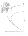
- Fig. 3 two typical curves A and B, each representing turbine available power curves P under a specific hydraulic condition at various turbine speeds, where no1 and no2 represent, respectively, the runaway speeds of the two conditions.
- no1 and no2 represent, respectively, the runaway speeds of the two conditions.
- stepwise path of the generated instantaneous power Pis which it follows under optimization control, until it reaches the curve's peak representing the maximum available power P.
- the generator which is directly coupled to the turbine, will accelerate freely, and without load.
- the synchronizer including the controller, will sense the generator's frequency and will synchronize itself to this frequency, while maintaining zero generating slip, i.e., this synchronization process will take place without loading the generator, until the generator reaches a steady state free running speed (no1 or no2, Fig. 3), or another pre-set speed.
- a steady state free running speed no1 or no2, Fig. 3
- the synchronizer activate the generator by inducing voltage and frequency therein at a constant ratio, starting from synchronization frequency (zero slip, zero power generation). From this point, frequency is gradually decreased to start the loading of the generator.
- the automatic control of the synchronizer will monitor the generated power and vary the frequency and voltage until the system delivers maximum generated power. As hydraulic conditions change, thereby varying the speed and/or torque on the generator's shaft, the system will automatically sense this occurrence and seek to restore a state of maximum generated power, by refinding the optimum frequency (steps 57-63, Fig. 2). If during the abovementioned control process the generator loading current should reach a pre-set maximum value, the system will stay at this point and not seek to reach maximum generated power.
- the system will stay at a constant speed and only periodically re-check for the maximum power e.g., every pre-set delay time of, for example, a few minutes. If within this delay time a big change in power, bigger than a predetermined value, has not occured (step 63-68, Fig. 2), the delay time is continued to be counted downwards. If a big change in power has occured (steps 65-66, Fig. 2), a search for the maximum power will start at once.
- the control parameter does not have to be at maximum generated power, it can be any other power level below the maximum power.
Landscapes
- Engineering & Computer Science (AREA)
- Power Engineering (AREA)
- Control Of Eletrric Generators (AREA)
- Nitrogen Condensed Heterocyclic Rings (AREA)
Priority Applications (1)
| Application Number | Priority Date | Filing Date | Title |
|---|---|---|---|
| AT88101203T ATE88600T1 (de) | 1987-01-30 | 1988-01-27 | System und methode zur optimierung der erzeugung elektrischer leistung. |
Applications Claiming Priority (2)
| Application Number | Priority Date | Filing Date | Title |
|---|---|---|---|
| IL81437A IL81437A (en) | 1987-01-30 | 1987-01-30 | Electronic controller and a system and method for optimizing generation of electrical power utilizing the same |
| IL81437 | 1987-01-30 |
Publications (2)
| Publication Number | Publication Date |
|---|---|
| EP0280876A1 true EP0280876A1 (fr) | 1988-09-07 |
| EP0280876B1 EP0280876B1 (fr) | 1993-04-21 |
Family
ID=11057507
Family Applications (1)
| Application Number | Title | Priority Date | Filing Date |
|---|---|---|---|
| EP88101203A Expired - Lifetime EP0280876B1 (fr) | 1987-01-30 | 1988-01-27 | système et méthode pour optimaliser la génération de puissance électrique |
Country Status (5)
| Country | Link |
|---|---|
| US (1) | US4841218A (fr) |
| EP (1) | EP0280876B1 (fr) |
| AT (1) | ATE88600T1 (fr) |
| DE (1) | DE3880349T2 (fr) |
| IL (1) | IL81437A (fr) |
Cited By (4)
| Publication number | Priority date | Publication date | Assignee | Title |
|---|---|---|---|---|
| EP0627811A1 (fr) * | 1993-06-02 | 1994-12-07 | SMH Management Services AG | Groupe électrogène |
| EP0644647A1 (fr) * | 1993-09-17 | 1995-03-22 | British Gas plc | Dispositif de production d'énergie électrique |
| WO2001073518A1 (fr) * | 2000-03-29 | 2001-10-04 | Abb Research Ltd. | Eolienne a helices a vitesse fixe et a vitesse variable |
| US6965174B2 (en) * | 2001-04-24 | 2005-11-15 | Aloys Wobben | Method for operating a wind turbine |
Families Citing this family (8)
| Publication number | Priority date | Publication date | Assignee | Title |
|---|---|---|---|---|
| US5153498A (en) * | 1989-11-07 | 1992-10-06 | Sundstrand Corporation | Generic control unit |
| DK171689B1 (da) * | 1993-09-01 | 1997-03-10 | Dancontrol Eng As | Fremgangsmåde til regulering af en elektrisk kobling for sammenkobling af et vekselspændingsnet med en asynkron generator samt kobling |
| US5761073A (en) * | 1995-02-09 | 1998-06-02 | Basler Electric Company | Programmable apparatus for synchronizing frequency and phase of two voltage sources |
| US5640060A (en) * | 1995-02-09 | 1997-06-17 | Basler Electric Company | Apparatus for synchronizing frequency and phase of two voltage sources |
| DE10162786B4 (de) * | 2001-12-20 | 2007-08-23 | Abb Patent Gmbh | Verfahren zur Leistungsermittlung, Messvorrichtung und Leistungsprüfstand für einen Prüfling |
| KR20130108497A (ko) * | 2010-01-12 | 2013-10-04 | 엠카 레겔테흐닉 아게 | 향상된 효율을 가진 비동기식 모터의 동작 방법 및 장치 |
| US8941961B2 (en) | 2013-03-14 | 2015-01-27 | Boulder Wind Power, Inc. | Methods and apparatus for protection in a multi-phase machine |
| US11059003B2 (en) * | 2018-04-10 | 2021-07-13 | Intrepid Potash, Inc. | Method for providing brine |
Citations (3)
| Publication number | Priority date | Publication date | Assignee | Title |
|---|---|---|---|---|
| US4296600A (en) * | 1979-02-06 | 1981-10-27 | Nissan Motor Company, Limited | Fuel control device for a gas turbine |
| EP0098047A1 (fr) * | 1982-05-25 | 1984-01-11 | Thamesmead Engineering Ltd | Systèmes électriques de régulation |
| DE3438893A1 (de) * | 1984-10-24 | 1986-04-24 | Arno Dipl.-Ing. 6301 Rabenau Eichmann | Stromerzeugungsanlage |
Family Cites Families (5)
| Publication number | Priority date | Publication date | Assignee | Title |
|---|---|---|---|---|
| US3991359A (en) * | 1969-02-13 | 1976-11-09 | Westinghouse Electric Corporation | Power regulation system |
| FR2413813A1 (fr) * | 1977-12-27 | 1979-07-27 | Gobaud Michel | Procede pour regler la tension d'un generateur electrique et systeme pour sa mise en oeuvre |
| IT1128783B (it) * | 1980-05-05 | 1986-06-04 | Fiat Auto Spa | Generatore autonomo di energia elettrica |
| US4525633A (en) * | 1982-09-28 | 1985-06-25 | Grumman Aerospace Corporation | Wind turbine maximum power tracking device |
| US4656413A (en) * | 1986-06-19 | 1987-04-07 | Bourbeau Frank J | Stabilized control system and method for coupling an induction generator to AC power mains |
-
1987
- 1987-01-30 IL IL81437A patent/IL81437A/xx not_active IP Right Cessation
-
1988
- 1988-01-27 EP EP88101203A patent/EP0280876B1/fr not_active Expired - Lifetime
- 1988-01-27 DE DE8888101203T patent/DE3880349T2/de not_active Expired - Fee Related
- 1988-01-27 AT AT88101203T patent/ATE88600T1/de not_active IP Right Cessation
- 1988-01-29 US US07/150,377 patent/US4841218A/en not_active Expired - Fee Related
Patent Citations (3)
| Publication number | Priority date | Publication date | Assignee | Title |
|---|---|---|---|---|
| US4296600A (en) * | 1979-02-06 | 1981-10-27 | Nissan Motor Company, Limited | Fuel control device for a gas turbine |
| EP0098047A1 (fr) * | 1982-05-25 | 1984-01-11 | Thamesmead Engineering Ltd | Systèmes électriques de régulation |
| DE3438893A1 (de) * | 1984-10-24 | 1986-04-24 | Arno Dipl.-Ing. 6301 Rabenau Eichmann | Stromerzeugungsanlage |
Non-Patent Citations (2)
| Title |
|---|
| IEEE 1980 IECI PROCEEDINGS, Papers Presented at IECI '80, "Applications of Mini and Microcomputers", Philadelphia, Pennsylvania, 17th-20th March 1980, pages 377-380, The Industrial Electronics and Control Instrumentation Society etc.; G.R.PHILLIPS: "A microprocessor-based engine/generator control system" * |
| PATENT ABSTRACTS OF JAPAN, vol. 9, no. 81 (E-307)[1804], 10th April 1985; & JP-A-59 213 299 (SUMITOMO SEIMITSU KOGYO K.K.) 03-12-1984 * |
Cited By (6)
| Publication number | Priority date | Publication date | Assignee | Title |
|---|---|---|---|---|
| EP0627811A1 (fr) * | 1993-06-02 | 1994-12-07 | SMH Management Services AG | Groupe électrogène |
| FR2706095A1 (fr) * | 1993-06-02 | 1994-12-09 | Smh Management Services Ag | Groupe électrogène. |
| EP0644647A1 (fr) * | 1993-09-17 | 1995-03-22 | British Gas plc | Dispositif de production d'énergie électrique |
| US5552640A (en) * | 1993-09-17 | 1996-09-03 | British Gas Plc | Electrical power generating arrangement with computer control for varying engine speed as a function of load demand |
| WO2001073518A1 (fr) * | 2000-03-29 | 2001-10-04 | Abb Research Ltd. | Eolienne a helices a vitesse fixe et a vitesse variable |
| US6965174B2 (en) * | 2001-04-24 | 2005-11-15 | Aloys Wobben | Method for operating a wind turbine |
Also Published As
| Publication number | Publication date |
|---|---|
| ATE88600T1 (de) | 1993-05-15 |
| US4841218A (en) | 1989-06-20 |
| EP0280876B1 (fr) | 1993-04-21 |
| IL81437A0 (en) | 1987-08-31 |
| DE3880349D1 (de) | 1993-05-27 |
| IL81437A (en) | 1990-09-17 |
| DE3880349T2 (de) | 1993-07-29 |
Similar Documents
| Publication | Publication Date | Title |
|---|---|---|
| Muljadi et al. | Power quality issues in a hybrid power system | |
| KR940002928B1 (ko) | 가변속도 윈드 터어빈 | |
| US7437215B2 (en) | Method and system for improving pump efficiency and productivity under power disturbance conditions | |
| US9450416B2 (en) | Wind turbine generator controller responsive to grid frequency change | |
| EP0280876A1 (fr) | système et méthode pour optimaliser la génération de puissance électrique | |
| KR101192240B1 (ko) | 유체역학적 전동장치를 구비하는 풍력발전설비를 위한제어시스템 | |
| JP4012604B2 (ja) | 交流電動機のトルクを制御する方法 | |
| US4461957A (en) | Speed tolerant alternator system for wind or hydraulic power generation | |
| US4427897A (en) | Fixed pitch wind turbine system utilizing aerodynamic stall | |
| GB2176667A (en) | Electric motor running system employing photovoltaic array source | |
| US6563229B2 (en) | Standby power system | |
| US4636707A (en) | Power generating equipment | |
| US4656413A (en) | Stabilized control system and method for coupling an induction generator to AC power mains | |
| WO2015041805A1 (fr) | Système et procédé pour le fonctionnement sans convertisseur de pompes entraînées par des moteurs | |
| US5886417A (en) | Electrical power generating installation and method of operating same | |
| EP2434138B1 (fr) | Procédés de contrôle de puissance | |
| CN100456627C (zh) | 发电设备 | |
| US7592711B1 (en) | Self-propelled wind power generator | |
| US4172692A (en) | Pumping plant fly wheel hydraulic surge protector | |
| KR101506530B1 (ko) | 발전기 출력 전압의 램프업을 위한 장치 및 그 방법 | |
| JPS59150982A (ja) | 風力発電設備の発電機保護装置 | |
| JP2001271736A (ja) | ポンプ水車運転制御システム | |
| Smith et al. | A multi-function electrical generator for a wind turbine | |
| JPH0127269B2 (fr) | ||
| JPS62255505A (ja) | タ−ビンのタ−ニング装置 |
Legal Events
| Date | Code | Title | Description |
|---|---|---|---|
| PUAI | Public reference made under article 153(3) epc to a published international application that has entered the european phase |
Free format text: ORIGINAL CODE: 0009012 |
|
| AK | Designated contracting states |
Kind code of ref document: A1 Designated state(s): AT CH DE FR GB IT LI NL SE |
|
| 17P | Request for examination filed |
Effective date: 19890125 |
|
| 17Q | First examination report despatched |
Effective date: 19910221 |
|
| RTI1 | Title (correction) | ||
| GRAA | (expected) grant |
Free format text: ORIGINAL CODE: 0009210 |
|
| RAP1 | Party data changed (applicant data changed or rights of an application transferred) |
Owner name: MEIR, ROSINNES Owner name: LOHER AKTIENGESELLSCHAFT |
|
| AK | Designated contracting states |
Kind code of ref document: B1 Designated state(s): AT CH DE FR GB IT LI NL SE |
|
| REF | Corresponds to: |
Ref document number: 88600 Country of ref document: AT Date of ref document: 19930515 Kind code of ref document: T |
|
| ITF | It: translation for a ep patent filed | ||
| REF | Corresponds to: |
Ref document number: 3880349 Country of ref document: DE Date of ref document: 19930527 |
|
| ET | Fr: translation filed | ||
| PLBE | No opposition filed within time limit |
Free format text: ORIGINAL CODE: 0009261 |
|
| STAA | Information on the status of an ep patent application or granted ep patent |
Free format text: STATUS: NO OPPOSITION FILED WITHIN TIME LIMIT |
|
| 26N | No opposition filed | ||
| EAL | Se: european patent in force in sweden |
Ref document number: 88101203.3 |
|
| PGFP | Annual fee paid to national office [announced via postgrant information from national office to epo] |
Ref country code: GB Payment date: 19981222 Year of fee payment: 12 |
|
| PGFP | Annual fee paid to national office [announced via postgrant information from national office to epo] |
Ref country code: FR Payment date: 19990118 Year of fee payment: 12 |
|
| PGFP | Annual fee paid to national office [announced via postgrant information from national office to epo] |
Ref country code: SE Payment date: 19990125 Year of fee payment: 12 |
|
| PGFP | Annual fee paid to national office [announced via postgrant information from national office to epo] |
Ref country code: AT Payment date: 19990127 Year of fee payment: 12 |
|
| PGFP | Annual fee paid to national office [announced via postgrant information from national office to epo] |
Ref country code: NL Payment date: 19990131 Year of fee payment: 12 |
|
| PGFP | Annual fee paid to national office [announced via postgrant information from national office to epo] |
Ref country code: CH Payment date: 19990210 Year of fee payment: 12 |
|
| PGFP | Annual fee paid to national office [announced via postgrant information from national office to epo] |
Ref country code: DE Payment date: 19991222 Year of fee payment: 13 |
|
| PG25 | Lapsed in a contracting state [announced via postgrant information from national office to epo] |
Ref country code: GB Free format text: LAPSE BECAUSE OF NON-PAYMENT OF DUE FEES Effective date: 20000127 Ref country code: AT Free format text: LAPSE BECAUSE OF NON-PAYMENT OF DUE FEES Effective date: 20000127 |
|
| PG25 | Lapsed in a contracting state [announced via postgrant information from national office to epo] |
Ref country code: SE Free format text: LAPSE BECAUSE OF NON-PAYMENT OF DUE FEES Effective date: 20000128 |
|
| PG25 | Lapsed in a contracting state [announced via postgrant information from national office to epo] |
Ref country code: LI Free format text: LAPSE BECAUSE OF NON-PAYMENT OF DUE FEES Effective date: 20000131 Ref country code: CH Free format text: LAPSE BECAUSE OF NON-PAYMENT OF DUE FEES Effective date: 20000131 |
|
| PG25 | Lapsed in a contracting state [announced via postgrant information from national office to epo] |
Ref country code: NL Free format text: LAPSE BECAUSE OF NON-PAYMENT OF DUE FEES Effective date: 20000801 |
|
| EUG | Se: european patent has lapsed |
Ref document number: 88101203.3 |
|
| GBPC | Gb: european patent ceased through non-payment of renewal fee |
Effective date: 20000127 |
|
| REG | Reference to a national code |
Ref country code: CH Ref legal event code: PL |
|
| PG25 | Lapsed in a contracting state [announced via postgrant information from national office to epo] |
Ref country code: FR Free format text: LAPSE BECAUSE OF NON-PAYMENT OF DUE FEES Effective date: 20000929 |
|
| NLV4 | Nl: lapsed or anulled due to non-payment of the annual fee |
Effective date: 20000801 |
|
| REG | Reference to a national code |
Ref country code: FR Ref legal event code: ST |
|
| PG25 | Lapsed in a contracting state [announced via postgrant information from national office to epo] |
Ref country code: DE Free format text: LAPSE BECAUSE OF NON-PAYMENT OF DUE FEES Effective date: 20011101 |
|
| PG25 | Lapsed in a contracting state [announced via postgrant information from national office to epo] |
Ref country code: IT Free format text: LAPSE BECAUSE OF NON-PAYMENT OF DUE FEES;WARNING: LAPSES OF ITALIAN PATENTS WITH EFFECTIVE DATE BEFORE 2007 MAY HAVE OCCURRED AT ANY TIME BEFORE 2007. THE CORRECT EFFECTIVE DATE MAY BE DIFFERENT FROM THE ONE RECORDED. Effective date: 20050127 |