EP0280907A1 - Montage pour la suppression d'oscillations - Google Patents
Montage pour la suppression d'oscillations Download PDFInfo
- Publication number
- EP0280907A1 EP0280907A1 EP88101630A EP88101630A EP0280907A1 EP 0280907 A1 EP0280907 A1 EP 0280907A1 EP 88101630 A EP88101630 A EP 88101630A EP 88101630 A EP88101630 A EP 88101630A EP 0280907 A1 EP0280907 A1 EP 0280907A1
- Authority
- EP
- European Patent Office
- Prior art keywords
- circuit
- frequency
- arrangement according
- signals
- influencing
- Prior art date
- Legal status (The legal status is an assumption and is not a legal conclusion. Google has not performed a legal analysis and makes no representation as to the accuracy of the status listed.)
- Granted
Links
Images


Classifications
-
- H—ELECTRICITY
- H04—ELECTRIC COMMUNICATION TECHNIQUE
- H04R—LOUDSPEAKERS, MICROPHONES, GRAMOPHONE PICK-UPS OR LIKE ACOUSTIC ELECTROMECHANICAL TRANSDUCERS; ELECTRIC HEARING AIDS; PUBLIC ADDRESS SYSTEMS
- H04R25/00—Electric hearing aids
- H04R25/45—Prevention of acoustic reaction, i.e. acoustic oscillatory feedback
- H04R25/453—Prevention of acoustic reaction, i.e. acoustic oscillatory feedback electronically
-
- H—ELECTRICITY
- H04—ELECTRIC COMMUNICATION TECHNIQUE
- H04R—LOUDSPEAKERS, MICROPHONES, GRAMOPHONE PICK-UPS OR LIKE ACOUSTIC ELECTROMECHANICAL TRANSDUCERS; ELECTRIC HEARING AIDS; PUBLIC ADDRESS SYSTEMS
- H04R25/00—Electric hearing aids
- H04R25/50—Customised settings for obtaining desired overall acoustical characteristics
- H04R25/505—Customised settings for obtaining desired overall acoustical characteristics using digital signal processing
Definitions
- the present invention relates to a circuit arrangement according to the preamble of patent claim 1.
- Circuits have recently been developed (for example from RIM-Elektronik, Kunststoff, or the circuits of US Pat. No. 4,232,192 and US Pat. No. 4,079,199) which recognize vibrations as such and then suppress them.
- Such circuits tap the useful signal between the input converter and a power amplifier connected upstream of the output converter and amplify it by means of an additional amplifier.
- the amplified signal is compared in a comparator stage with a threshold voltage and fed into a phase locked loop (so-called phase locked loop or PLL for short).
- the PLL recognizes one Vibration, if it occurs, and provides a suppression signal to a notch filter upstream of the power amplifier that suppresses the frequency range of the vibration (or, in the case of U.S. Patent No. 4,079,199, the gain is reduced).
- a PLL becomes unstable when the input signal disappears. It drifts. The result of the drift is a periodic acoustic interference signal.
- the object of the present invention is to construct a vibration suppression circuit which, when a vibration occurs in the useful signal, suppresses this vibration and remains stable (does not begin to drift) when the input signal disappears.
- the PLL in the circuit arrangement is replaced by an oscillation frequency search circuit which comprises a frequency detection device for the frequency found, which continues to emit a signal even when the oscillation disappears, which keeps the influencing circuit (e.g. notch filter) in a fixed state.
- the influencing circuit e.g. notch filter
- a preferred embodiment of the invention results from the dependent claim 2.
- the circuit between the power amplifier and output converter switched on, which makes it possible to dispense with the additional amplifier used in the prior art.
- the circuit arrangement can be made cheaper and, particularly in the case of hearing aids, more space-saving.
- Fig. 1 shows a circuit arrangement according to the invention, which can be installed, for example, in a hearing aid. It comprises a microphone 1 as an acoustic input converter, which converts acoustic input signals into electrical signals SO, an acoustic output converter 2 (which is designed either as a loudspeaker or, especially in hearing aids, as a so-called receiver), a power amplifier 3 connected upstream of the output converter 2 and one Vibration suppression circuit 4 designed according to the invention.
- a microphone 1 as an acoustic input converter, which converts acoustic input signals into electrical signals SO
- an acoustic output converter 2 which is designed either as a loudspeaker or, especially in hearing aids, as a so-called receiver
- a power amplifier 3 connected upstream of the output converter 2
- Vibration suppression circuit 4 designed according to the invention.
- the vibration suppression circuit 4 is designed as an electrical feedback circuit. It suppresses electrical signals that are generated due to acoustic feedback effects and that usually lead to undamped vibrations in the circuit.
- the feedback effect is indicated in FIG. 1 with a dashed arrow line between acoustic output transducer 2 and microphone 1.
- An acoustic useful signal SE together with an acoustic feedback signal SR is converted in the microphone 1 into an electrical signal S0.
- the output signal S5 of the vibration suppression circuit 4 is subtracted from this signal S0 in a subtractor 5 from the signal S0.
- the remaining signal S1 is amplified in a non-inverting power amplifier 3 to a signal S2.
- the signal S2 is converted back into an acoustic signal SA in the output converter 2.
- the signal S2 is fed to the vibration suppression circuit 4 as an input signal.
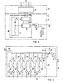
- the function of the vibration suppression circuit 4 consists of a vibration detection circuit 6, a vibration frequency search circuit 7 and an influencing circuit 8.
- the input signal S2 is passed to the vibration detection circuit 6. It is also fed to the influencing circuit 8.
- the vibration detection circuit 6 it is checked whether the signal S2 contains a vibration based on acoustic feedback effects. If an oscillation is present, an oscillation detection signal S3 is emitted.
- the signal S3 sets the oscillation frequency search circuit 7 into operation, a sequence of signals S4 being emitted by the oscillation frequency search circuit 7 until the oscillation detection signal S3 at the output of the oscillation detection circuit 6 disappears.
- the Vibration detection signal S3 pending signal S4 at the output of the oscillation frequency search circuit 7 is held by the search circuit 7 until a new oscillation occurs.
- the signals S4 control the influencing circuit 8, in the sense that frequency ranges which are to be assigned to a detected oscillation are largely suppressed in the entire captured frequency spectrum of the signal SO by means of a filter.
- the output signal S5 of the influencing circuit 8 is the output signal of the vibration suppression circuit 4.
- the vibration detection circuit 6 checks the input signal S2 for these properties. In a first stage, the amplitude of the input signal S2 is compared with a first threshold voltage UT1 by means of a first comparator 9. If the amplitude of S2 exceeds the threshold UT1, a square wave voltage S21 is generated.
- the following stage comprises an RC element with an ohmic resistor 10, diode 10 ⁇ and capacitor 11 and a second comparator 12.
- the capacitor 11 is quickly charged by the signal S21 via the diode 10 and discharged again via the resistor 10 with a predetermined time constant.
- the time constant together with the threshold voltage UT2 of the second comparator 12 determines the minimum frequency to which the vibration detection circuit 6 responds. If a small time constant is selected, then the vibration detection circuit 6 essentially only responds to high-frequency signals. In the case of low-frequency signals, the capacitor 11 has sufficient time to discharge below the threshold voltage UT2 of the second comparator 12. These low-frequency signals are therefore not detected. This ensures that the vibration detection circuit 6 only responds to signals that derive from acoustic feedback effects, while portions of the useful signal (eg voice signal) that occur periodically at a lower frequency are not taken into account.
- the useful signal eg voice signal
- output signals S23 are released to a third stage 13 to 16.
- the output signals S23 are square-wave voltages which have the same duration as the threshold value violations of the signals S22.
- the signals S23 thus reflect how long a large, high-frequency input signal lasts.
- the third stage comprises a diode 13, an RC element 14, 15 and a third comparator 16. With the signal S23, the capacitor 15 is charged via the resistor 14. Resistor 14 and capacitor 15 are dimensioned so that the charging time constant is large, e.g. 0.5 to 2 seconds. If the output voltage S23 drops only briefly, the capacitor 15 is immediately completely discharged via the diode 13.
- the capacitor 15 charges to such an extent that the voltage exceeds the threshold UT3 of the subsequent third comparator 16.
- the input signal S2 fulfills all vibration detection criteria and the signal S3 output by the comparator 16 is considered to be a vibration detection signal.
- the oscillation frequency search circuit 7 is arranged between the oscillation detection circuit 6 and the influencing circuit 8 and controls the influencing circuit 8 in such a way that detected oscillations are suppressed.
- a first device 17 of the search circuit 7 generates digital frequency-determining signals S33 and is controlled by the vibration detection signals S3.
- the main component of the first device 17 is a counting device 18 which a counter 19, a counting direction switch 20 and a reset element 21, also called "power-on reset".
- the first device 17 includes an oscillator 22 and an associated AND gate 23.
- the counter 19 also serves as a holding device for the frequencies of the detected vibration, as will be explained in more detail below.
- the reset element 21 ensures that the output signals S32 on all four output lines of the counter 19 are in the zero state (also referred to as the “low” state).
- This 0000 value is digitally incremented by one each time a pulse S31 ("high” state) is registered at the input of the counter 19. After all four output lines have been switched to "high”, the original zero state is restored at the next pulse S31 and the step-up sequence is repeated.
- a pulse S31 is only generated if a vibration detection pulse S3 is present at the AND gate 22 connected upstream of the counter 19. If this is the case, then the pulses S31 ⁇ generated by the oscillator 22 are forwarded as step-up pulses S31.
- the oscillator 22 therefore determines the speed at which the counter 19 is advanced.
- the counter 19 continues to switch the output pulses S32 until the vibration detection signal S3 disappears. (Signal S3 disappears if the oscillation has been suppressed by the influencing circuit 8.) When the signal S3 disappears, the counter 19 receives no further pulses S31 and remains in the set state until a new oscillation detection signal S3 occurs.
- the counter 19 thus stores the set state and therefore, together with the AND gate 23, serves as a holding device for holding the frequency of the detected vibration at the influencing circuit 8. It is advantageous to design the oscillation frequency search circuit 7 as a holding device, since the vibration suppression circuit 4 does not drift can and a return of the suppressed vibration is avoided.
- the first device 17 also includes at the output of the counter 19 a counting direction switch 20.
- This has the effect that a sudden change from 111 to 000 is avoided in the digital frequency-determining output signals S33, by counting down every second sequence by inversion of the input signals S32 from 111 to 000 becomes.
- This is advantageous in that the filter arranged in the influencing circuit 8 for suppressing the oscillation frequency when the counting direction is reversed does not jump from one end to the other end of the frequency spectrum, but instead moves back and forth in the frequency spectrum.
- a second device 24 of the oscillation frequency search circuit 7 samples the frequency-determining signals S33 of the first device 17 (output of the counting direction switch 20) and controls the influencing circuit 8 via the signals S4.
- a decoder 25 transmits the eight signal possibilities arriving via three lines to eight different lines. These eight signals S4 control the influencing circuit 8 in the sense that they determine which frequency range in the controllable frequency spectrum is filtered by the influencing circuit 8.
- the decoder 25 controls the influencing circuit 8 by means of a discretely variable resistor 26.
- the influencing circuit 8 also comprises further ohmic resistors 30, capacitors 31 and an amplifier 32, which are arranged in the form of a bandpass filter.
- a bandpass filter is e.g. known from the book "Semiconductor Circuit Technology” by Tietze and Schenk (Springer-Verlag Berlin, Heidelberg, 7th edition (1985), pages 419-421). Since the bandpass filter is designed as a negative feedback of the power amplifier 3, the circuit 8 simulates a notch filter, which forms a suction circuit at the resonance frequency. The bandwidth and gain of the filter are independent of the discretely variable resistor 26. The resonance frequency can thus be varied by changing the resistance values in the resistor 26 without influencing the bandwidth or amplification.
- the output resistor 33 determines the weight of the feedback S5 on the subtractor 5 (see FIG. 1).
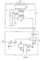
- FIG. 5 Another possibility of influencing vibrations (modification of FIG. 4) is shown in FIG. 5.
- a CR high-pass filter is used in the influencing circuit 8 'instead of a band-pass filter.
- this filter simulates a variable capacitor that enables smoothing of the acoustic reproduction curve and has a low-pass effect.
- the above-described vibration detection circuit 6 and vibration frequency search circuit 7 can be used unchanged in this embodiment.
- the circuit 8 ⁇ could be designed as a phase shifter, phase switch or gain reducer.
- Figure 6 shows e.g. a variant of the oscillation detection circuit 6 and the oscillation frequency search circuit 7.
- the third comparator stage 13 to 16 of the oscillation detection circuit 6 ' is replaced by a counter stage which comprises an inverter 36, a digital counter 37 and an AND gate 38.
- the input signal is checked in the same way as in the exemplary embodiment corresponding to FIG. 2 according to the vibration characteristics "large amplitude" and "high frequencies". However, an output signal S23 is digitally processed to determine whether the large, high-frequency input signal is long-lasting.
- Counter 37 has two signal inputs: an input for the square wave voltage S21 and a reset input which, together with the inverter 36, constantly resets the counter 37 to the zero state, except when a signal S23 occurs. As long as a signal S23 is present, the counter 37 counts the square-wave signals S21. After a certain number of signals S21 has occurred, the input signal is regarded as a recognized vibration. The counter 37 then generates step pulses S3 together with the AND gate 38. These advance pulses can be given directly to the counter 19 of the search circuit 7 '. This circuit variant therefore does not require an oscillator.
Landscapes
- Acoustics & Sound (AREA)
- General Health & Medical Sciences (AREA)
- Neurosurgery (AREA)
- Otolaryngology (AREA)
- Physics & Mathematics (AREA)
- Engineering & Computer Science (AREA)
- Health & Medical Sciences (AREA)
- Signal Processing (AREA)
- Amplifiers (AREA)
- Stereo-Broadcasting Methods (AREA)
- Coating With Molten Metal (AREA)
- Gyroscopes (AREA)
- Stabilization Of Oscillater, Synchronisation, Frequency Synthesizers (AREA)
Priority Applications (1)
| Application Number | Priority Date | Filing Date | Title |
|---|---|---|---|
| AT88101630T ATE68310T1 (de) | 1987-02-17 | 1988-02-04 | Schaltungsanordnung zum unterdruecken von schwingungen. |
Applications Claiming Priority (2)
| Application Number | Priority Date | Filing Date | Title |
|---|---|---|---|
| DE3704999 | 1987-02-17 | ||
| DE3704999 | 1987-02-17 |
Publications (2)
| Publication Number | Publication Date |
|---|---|
| EP0280907A1 true EP0280907A1 (fr) | 1988-09-07 |
| EP0280907B1 EP0280907B1 (fr) | 1991-10-09 |
Family
ID=6321173
Family Applications (1)
| Application Number | Title | Priority Date | Filing Date |
|---|---|---|---|
| EP88101630A Expired - Lifetime EP0280907B1 (fr) | 1987-02-17 | 1988-02-04 | Montage pour la suppression d'oscillations |
Country Status (5)
| Country | Link |
|---|---|
| US (1) | US4815140A (fr) |
| EP (1) | EP0280907B1 (fr) |
| AT (1) | ATE68310T1 (fr) |
| DE (1) | DE3865319D1 (fr) |
| DK (1) | DK77888A (fr) |
Cited By (1)
| Publication number | Priority date | Publication date | Assignee | Title |
|---|---|---|---|---|
| EP0600164A1 (fr) * | 1992-09-08 | 1994-06-08 | Alcatel SEL Aktiengesellschaft | Procédé pour l'amélioration de la qualité de transmission d'un dispositif électro-acoustique |
Families Citing this family (9)
| Publication number | Priority date | Publication date | Assignee | Title |
|---|---|---|---|---|
| US4985925A (en) * | 1988-06-24 | 1991-01-15 | Sensor Electronics, Inc. | Active noise reduction system |
| US5091952A (en) * | 1988-11-10 | 1992-02-25 | Wisconsin Alumni Research Foundation | Feedback suppression in digital signal processing hearing aids |
| US6563931B1 (en) | 1992-07-29 | 2003-05-13 | K/S Himpp | Auditory prosthesis for adaptively filtering selected auditory component by user activation and method for doing same |
| US5412734A (en) * | 1993-09-13 | 1995-05-02 | Thomasson; Samuel L. | Apparatus and method for reducing acoustic feedback |
| US6137888A (en) * | 1997-06-02 | 2000-10-24 | Nortel Networks Corporation | EM interference canceller in an audio amplifier |
| AU2004201374B2 (en) * | 2004-04-01 | 2010-12-23 | Phonak Ag | Audio amplification apparatus |
| AU2003236382B2 (en) * | 2003-08-20 | 2011-02-24 | Phonak Ag | Feedback suppression in sound signal processing using frequency transposition |
| US7756276B2 (en) * | 2003-08-20 | 2010-07-13 | Phonak Ag | Audio amplification apparatus |
| EP2053876B1 (fr) * | 2007-10-18 | 2010-05-26 | Siemens Medical Instruments Pte. Ltd. | Dispositif auditif doté d'un raccordement commun pour le blindage et l'identification d'un récepteur |
Citations (3)
| Publication number | Priority date | Publication date | Assignee | Title |
|---|---|---|---|---|
| US4079199A (en) * | 1977-05-25 | 1978-03-14 | Patronis Jr Eugene T | Acoustic feedback detector and automatic gain control |
| US4091236A (en) * | 1976-09-07 | 1978-05-23 | The University Of Akron | Automatically tunable notch filter and method for suppression of acoustical feedback |
| US4232192A (en) * | 1978-05-01 | 1980-11-04 | Starkey Labs, Inc. | Moving-average notch filter |
Family Cites Families (1)
| Publication number | Priority date | Publication date | Assignee | Title |
|---|---|---|---|---|
| NL7612358A (nl) * | 1976-11-08 | 1978-05-10 | Philips Nv | Versterkerinrichting voor akoestische signalen voorzien van middelen voor het onderdrukken van ongewenste stoorsignalen. |
-
1988
- 1988-02-04 US US07/152,326 patent/US4815140A/en not_active Expired - Fee Related
- 1988-02-04 AT AT88101630T patent/ATE68310T1/de not_active IP Right Cessation
- 1988-02-04 EP EP88101630A patent/EP0280907B1/fr not_active Expired - Lifetime
- 1988-02-04 DE DE8888101630T patent/DE3865319D1/de not_active Expired - Lifetime
- 1988-02-16 DK DK077888A patent/DK77888A/da not_active Application Discontinuation
Patent Citations (3)
| Publication number | Priority date | Publication date | Assignee | Title |
|---|---|---|---|---|
| US4091236A (en) * | 1976-09-07 | 1978-05-23 | The University Of Akron | Automatically tunable notch filter and method for suppression of acoustical feedback |
| US4079199A (en) * | 1977-05-25 | 1978-03-14 | Patronis Jr Eugene T | Acoustic feedback detector and automatic gain control |
| US4232192A (en) * | 1978-05-01 | 1980-11-04 | Starkey Labs, Inc. | Moving-average notch filter |
Non-Patent Citations (1)
| Title |
|---|
| HEARING INSTRUMENTS, Band 37, Nr. 4, April 1986, Seiten 34,36,41,51, Cleveland, Ohio, US; D.A. PREVES et al.: "A feedback stabilizing circuit for hearing aids" * |
Cited By (1)
| Publication number | Priority date | Publication date | Assignee | Title |
|---|---|---|---|---|
| EP0600164A1 (fr) * | 1992-09-08 | 1994-06-08 | Alcatel SEL Aktiengesellschaft | Procédé pour l'amélioration de la qualité de transmission d'un dispositif électro-acoustique |
Also Published As
| Publication number | Publication date |
|---|---|
| US4815140A (en) | 1989-03-21 |
| ATE68310T1 (de) | 1991-10-15 |
| DE3865319D1 (de) | 1991-11-14 |
| DK77888A (da) | 1988-08-18 |
| DK77888D0 (da) | 1988-02-16 |
| EP0280907B1 (fr) | 1991-10-09 |
Similar Documents
| Publication | Publication Date | Title |
|---|---|---|
| EP0280909B1 (fr) | Montage pour la détection d'oscillations | |
| DE60028779T2 (de) | Rückkopplungsanullierung mit niederfrequenzeingang | |
| DE69933627T2 (de) | Vorrichtung und Verfahren zur Anpassung des Phasen- und Amplitudenfrequenzgangs eines Mikrofons | |
| DE2658301C2 (de) | Hörgerät | |
| DE69125601T2 (de) | Geräuschverminderndes system | |
| DE3802903C2 (fr) | ||
| DE2747821C2 (de) | Verstärkeranordnung für akustische Signale mit Mitteln zum Unterdrücken unerwünschter Störsignale | |
| DE3904505C2 (de) | Rausch-Unterdrückungssystem für MW-Radioempfänger | |
| DE3512999A1 (de) | Differentialhoerhilfe mit programmierbarem frequenzgang | |
| EP0280907B1 (fr) | Montage pour la suppression d'oscillations | |
| DE10129850B4 (de) | Verstärkereinrichtung mit frequenzgangkompensierender Verstärkerreaktanz sowie Verwendung der Verstärkereinrichtung | |
| DE19611026C2 (de) | Klirrunterdrückung bei Hörgeräten mit AGC | |
| EP1238468B1 (fr) | Procede et systeme pour l'antiparasitage dans un circuit recepteur | |
| DE10244184B3 (de) | Feedbackkompensation für Hörgeräte mit Systemabstandsschätzung | |
| DE102016116421A1 (de) | Sensoranordnung mit optimierter gruppenlaufzeit und verfahren zur signalverarbeitung | |
| DE69327951T2 (de) | Hörgerät mit ausgleich der akustischen rückkopplung | |
| EP0578021A2 (fr) | Prothèse auditive | |
| EP1052881B1 (fr) | Prothèse acoustique avec détecteur d'oscillations et méthode de détection d'oscillations dans une prothèse acoustique | |
| EP0586831B1 (fr) | Procédé d'absorption du son pour véhicules automobiles | |
| DE3606973A1 (de) | Schaltungsanordnung fuer ein freisprechtelefon | |
| EP0485357B1 (fr) | Prothèse auditive avec circuit de filtrage | |
| AT403978B (de) | Einkanal-schaltung für ein hörgerät | |
| DE2758476A1 (de) | Rauschunterdrueckungsschaltung | |
| DE19632067B4 (de) | Niederfrequenzsignal-Verstärkerschaltung | |
| EP1453355A1 (fr) | Traitement de signal dans un appareil auditif |
Legal Events
| Date | Code | Title | Description |
|---|---|---|---|
| PUAI | Public reference made under article 153(3) epc to a published international application that has entered the european phase |
Free format text: ORIGINAL CODE: 0009012 |
|
| AK | Designated contracting states |
Kind code of ref document: A1 Designated state(s): AT CH DE FR GB IT LI NL |
|
| 17P | Request for examination filed |
Effective date: 19880923 |
|
| 17Q | First examination report despatched |
Effective date: 19900808 |
|
| GRAA | (expected) grant |
Free format text: ORIGINAL CODE: 0009210 |
|
| AK | Designated contracting states |
Kind code of ref document: B1 Designated state(s): AT CH DE FR GB IT LI NL |
|
| REF | Corresponds to: |
Ref document number: 68310 Country of ref document: AT Date of ref document: 19911015 Kind code of ref document: T |
|
| REF | Corresponds to: |
Ref document number: 3865319 Country of ref document: DE Date of ref document: 19911114 |
|
| ET | Fr: translation filed | ||
| ITF | It: translation for a ep patent filed | ||
| GBT | Gb: translation of ep patent filed (gb section 77(6)(a)/1977) | ||
| PLBI | Opposition filed |
Free format text: ORIGINAL CODE: 0009260 |
|
| 26 | Opposition filed |
Opponent name: PHILIPS ELECTRONICS N.V. Effective date: 19920629 |
|
| NLR1 | Nl: opposition has been filed with the epo |
Opponent name: PHILIPS ELECTRONICS N.V. |
|
| PGFP | Annual fee paid to national office [announced via postgrant information from national office to epo] |
Ref country code: GB Payment date: 19930122 Year of fee payment: 6 |
|
| PGFP | Annual fee paid to national office [announced via postgrant information from national office to epo] |
Ref country code: AT Payment date: 19930127 Year of fee payment: 6 |
|
| RAP2 | Party data changed (patent owner data changed or rights of a patent transferred) |
Owner name: SIEMENS AUDIOLOGISCHE TECHNIK GMBH |
|
| NLT2 | Nl: modifications (of names), taken from the european patent patent bulletin |
Owner name: SIEMENS AUDIOLOGISCHE TECHNIK GMBH TE ERLANGEN, BO |
|
| PG25 | Lapsed in a contracting state [announced via postgrant information from national office to epo] |
Ref country code: GB Effective date: 19940204 Ref country code: AT Effective date: 19940204 |
|
| PGFP | Annual fee paid to national office [announced via postgrant information from national office to epo] |
Ref country code: FR Payment date: 19940224 Year of fee payment: 7 |
|
| PGFP | Annual fee paid to national office [announced via postgrant information from national office to epo] |
Ref country code: NL Payment date: 19940228 Year of fee payment: 7 |
|
| GBPC | Gb: european patent ceased through non-payment of renewal fee |
Effective date: 19940204 |
|
| PG25 | Lapsed in a contracting state [announced via postgrant information from national office to epo] |
Ref country code: NL Effective date: 19950901 |
|
| PG25 | Lapsed in a contracting state [announced via postgrant information from national office to epo] |
Ref country code: FR Effective date: 19951031 |
|
| NLV4 | Nl: lapsed or anulled due to non-payment of the annual fee |
Effective date: 19950901 |
|
| REG | Reference to a national code |
Ref country code: FR Ref legal event code: ST |
|
| PGFP | Annual fee paid to national office [announced via postgrant information from national office to epo] |
Ref country code: DE Payment date: 19990419 Year of fee payment: 12 |
|
| PGFP | Annual fee paid to national office [announced via postgrant information from national office to epo] |
Ref country code: CH Payment date: 19990514 Year of fee payment: 12 |
|
| RDAH | Patent revoked |
Free format text: ORIGINAL CODE: EPIDOS REVO |
|
| RDAG | Patent revoked |
Free format text: ORIGINAL CODE: 0009271 |
|
| STAA | Information on the status of an ep patent application or granted ep patent |
Free format text: STATUS: PATENT REVOKED |
|
| 27W | Patent revoked |
Effective date: 20000423 |
|
| REG | Reference to a national code |
Ref country code: CH Ref legal event code: PL |
|
| PLAB | Opposition data, opponent's data or that of the opponent's representative modified |
Free format text: ORIGINAL CODE: 0009299OPPO |