EP0280964A1 - Universalbatterie - Google Patents
Universalbatterie Download PDFInfo
- Publication number
- EP0280964A1 EP0280964A1 EP88102373A EP88102373A EP0280964A1 EP 0280964 A1 EP0280964 A1 EP 0280964A1 EP 88102373 A EP88102373 A EP 88102373A EP 88102373 A EP88102373 A EP 88102373A EP 0280964 A1 EP0280964 A1 EP 0280964A1
- Authority
- EP
- European Patent Office
- Prior art keywords
- battery
- housing
- battery according
- universal battery
- strip
- Prior art date
- Legal status (The legal status is an assumption and is not a legal conclusion. Google has not performed a legal analysis and makes no representation as to the accuracy of the status listed.)
- Granted
Links
- 230000003014 reinforcing effect Effects 0.000 claims description 5
- 238000004873 anchoring Methods 0.000 claims description 3
- 230000002787 reinforcement Effects 0.000 abstract 1
- 230000006378 damage Effects 0.000 description 1
- 230000000694 effects Effects 0.000 description 1
- 229920001971 elastomer Polymers 0.000 description 1
- 239000000806 elastomer Substances 0.000 description 1
- 239000000463 material Substances 0.000 description 1
- 238000000034 method Methods 0.000 description 1
- 238000005192 partition Methods 0.000 description 1
- 229920003023 plastic Polymers 0.000 description 1
- 239000004033 plastic Substances 0.000 description 1
- 238000003466 welding Methods 0.000 description 1
Images


Classifications
-
- B—PERFORMING OPERATIONS; TRANSPORTING
- B60—VEHICLES IN GENERAL
- B60R—VEHICLES, VEHICLE FITTINGS, OR VEHICLE PARTS, NOT OTHERWISE PROVIDED FOR
- B60R16/00—Electric or fluid circuits specially adapted for vehicles and not otherwise provided for; Arrangement of elements of electric or fluid circuits specially adapted for vehicles and not otherwise provided for
- B60R16/02—Electric or fluid circuits specially adapted for vehicles and not otherwise provided for; Arrangement of elements of electric or fluid circuits specially adapted for vehicles and not otherwise provided for electric constitutive elements
- B60R16/04—Arrangement of batteries
-
- H—ELECTRICITY
- H01—ELECTRIC ELEMENTS
- H01M—PROCESSES OR MEANS, e.g. BATTERIES, FOR THE DIRECT CONVERSION OF CHEMICAL ENERGY INTO ELECTRICAL ENERGY
- H01M50/00—Constructional details or processes of manufacture of the non-active parts of electrochemical cells other than fuel cells, e.g. hybrid cells
- H01M50/20—Mountings; Secondary casings or frames; Racks, modules or packs; Suspension devices; Shock absorbers; Transport or carrying devices; Holders
- H01M50/247—Mountings; Secondary casings or frames; Racks, modules or packs; Suspension devices; Shock absorbers; Transport or carrying devices; Holders specially adapted for portable devices, e.g. mobile phones, computers, hand tools or pacemakers
-
- H—ELECTRICITY
- H01—ELECTRIC ELEMENTS
- H01M—PROCESSES OR MEANS, e.g. BATTERIES, FOR THE DIRECT CONVERSION OF CHEMICAL ENERGY INTO ELECTRICAL ENERGY
- H01M50/00—Constructional details or processes of manufacture of the non-active parts of electrochemical cells other than fuel cells, e.g. hybrid cells
- H01M50/10—Primary casings; Jackets or wrappings
- H01M50/102—Primary casings; Jackets or wrappings characterised by their shape or physical structure
- H01M50/112—Monobloc comprising multiple compartments
- H01M50/114—Monobloc comprising multiple compartments specially adapted for lead-acid cells
-
- H—ELECTRICITY
- H01—ELECTRIC ELEMENTS
- H01M—PROCESSES OR MEANS, e.g. BATTERIES, FOR THE DIRECT CONVERSION OF CHEMICAL ENERGY INTO ELECTRICAL ENERGY
- H01M50/00—Constructional details or processes of manufacture of the non-active parts of electrochemical cells other than fuel cells, e.g. hybrid cells
- H01M50/20—Mountings; Secondary casings or frames; Racks, modules or packs; Suspension devices; Shock absorbers; Transport or carrying devices; Holders
- H01M50/244—Secondary casings; Racks; Suspension devices; Carrying devices; Holders characterised by their mounting method
-
- H—ELECTRICITY
- H01—ELECTRIC ELEMENTS
- H01M—PROCESSES OR MEANS, e.g. BATTERIES, FOR THE DIRECT CONVERSION OF CHEMICAL ENERGY INTO ELECTRICAL ENERGY
- H01M50/00—Constructional details or processes of manufacture of the non-active parts of electrochemical cells other than fuel cells, e.g. hybrid cells
- H01M50/20—Mountings; Secondary casings or frames; Racks, modules or packs; Suspension devices; Shock absorbers; Transport or carrying devices; Holders
- H01M50/256—Carrying devices, e.g. belts
-
- H—ELECTRICITY
- H01—ELECTRIC ELEMENTS
- H01M—PROCESSES OR MEANS, e.g. BATTERIES, FOR THE DIRECT CONVERSION OF CHEMICAL ENERGY INTO ELECTRICAL ENERGY
- H01M50/00—Constructional details or processes of manufacture of the non-active parts of electrochemical cells other than fuel cells, e.g. hybrid cells
- H01M50/20—Mountings; Secondary casings or frames; Racks, modules or packs; Suspension devices; Shock absorbers; Transport or carrying devices; Holders
- H01M50/262—Mountings; Secondary casings or frames; Racks, modules or packs; Suspension devices; Shock absorbers; Transport or carrying devices; Holders with fastening means, e.g. locks
-
- Y—GENERAL TAGGING OF NEW TECHNOLOGICAL DEVELOPMENTS; GENERAL TAGGING OF CROSS-SECTIONAL TECHNOLOGIES SPANNING OVER SEVERAL SECTIONS OF THE IPC; TECHNICAL SUBJECTS COVERED BY FORMER USPC CROSS-REFERENCE ART COLLECTIONS [XRACs] AND DIGESTS
- Y02—TECHNOLOGIES OR APPLICATIONS FOR MITIGATION OR ADAPTATION AGAINST CLIMATE CHANGE
- Y02E—REDUCTION OF GREENHOUSE GAS [GHG] EMISSIONS, RELATED TO ENERGY GENERATION, TRANSMISSION OR DISTRIBUTION
- Y02E60/00—Enabling technologies; Technologies with a potential or indirect contribution to GHG emissions mitigation
- Y02E60/10—Energy storage using batteries
Definitions
- the invention relates to a universal battery for motor vehicles, in particular cars and light trucks, according to the preamble of patent claim 1.
- a universal battery of the type mentioned is already known (DE-GM 86 02 061).
- the handles serve in the opened position on the battery cover for some protection of the battery poles in the manner of a frame encompassing all four poles, but otherwise the battery poles are not protected upwards.
- a holding strip is fastened, in the recesses of which holding members can engage in order to fasten the battery by means of the holding members on a plate in a frame or the like.
- the invention has for its object to provide the known battery in a simple manner so that it can be used even more universally and can be easily installed in virtually any car.
- the battery has a housing with a base strip on the lower edge, mounting strips and a battery cover with 2 or 4-pole connection (2 plus and 2 minus poles) and in particular with a hood with handles.
- the base bar is not only arranged on one or two opposite sides of the housing, but on all four sides of the same.
- the housing 1 forms a unit with the base strip 2, which is essentially completely encircling the outer edge of the housing.
- the base bar 2 may also be missing. It is important that parts of the base strip 2 are present on all four sides of the housing 1, the long sides LS and the end faces SS.
- the parts of the base strip 2 located on the longitudinal sides LS can have a different overall height H G than the base strip parts located on the end faces.
- the base strip 2 with a height H G of, for example, 10.5 mm has three or more recesses 3 through which the battery is fastened in the car by means of holding members. 3a, the base bar 2 protrudes laterally from the outer wall of the housing 1 and then bends downward to form a groove 2b which is open at the bottom.
- the battery is shown in cross-section from the longitudinal side LS, for example, the lower fastening strip 5 as a plug-in strip with a height H5 of 29 mm and, for example, the lower fastening strip 4, in turn, can be plugged on as a plug-in strip at the bottom right of the base strip 2, which increases the height H G of the base bar 2 by plugging or screwing or the like fastenings from 10.5 mm to 19.5 mm.
- the exchangeable and removable plug strips 4, 5 are fixed in holes 2a (only indicated) in the base strip 2.
- the hood 7 is attached to the battery cover 6.
- the handles 8 are shown lying down. According to FIG. 4, the battery can be brought in cross-section from the end face SS with the carrying handles 8 once in a horizontal position and once - alternatively - in a vertical position from the remote to the portable position.
- the hood 7 is shown from its long side LS. In order to be able to anchor the hood 7 on the battery cover 6, it is equipped with snaps 9 in the form of hook-shaped elements.
- the hood 7 has two openings 10 each, which connect the cables to a pair of vir battery poles 100, 101 enable.
- One battery pole 100, 101 is arranged in one of the four corner regions of the battery, which is essentially rectangular in plan view.
- the slots 11 in the hood 7 serve for anchoring the handles 8 (in section A-A of FIG. 6, the end face SS of the hood 7 can be seen).
- the handle 8 is shown on the long side.
- the two knob-like outwardly protruding elevations 21 ensure the anchoring of the handles 8 in the slots 11 of the hood 7; however, they can also be dismantled as required without material destruction.
- the handle 8 is shown lying with the reinforcing ribs 13 and according to FIG. 9, the handle 8 is shown laterally and partially in section with the knob-like elevations 21 on the brackets 12.
- FIG. 11 shows the battery cover 6 from below.
- the same-pole battery poles 100, 101 are connected to one another with the double lead sleeve 15.
- a cover with only one plus and one minus pole can also be used, which - held by centering lugs - can be modified with an outer bridge into a double-pole cover.
- the battery cover 6 is connected to the housing 1 in the usual mirror welding process.
- centering ribs 16 directed towards the inside or towards the housing 1 and its partitions 102 or ribs are attached to the battery cover.
- the low connector strip 4 with reinforcing ribs 17, snap-on snap-on catches 18 and recesses 3, which can be snapped into the holes 2a of the base strip 2 and then expanded again, is shown.
- the bar 4 With the Aussteckschnapper 18, the bar 4 is fixed on the base bar 2.
- the recesses 3, on the other hand, serve to fasten the battery in the car, holding members engage in the recesses 3.
- the higher header 5 is provided with reinforcing ribs 19, corresponding clip-on snaps 18 and semi-circular incisions 20.
- the bar 5 With the clip 18, the bar 5 is in turn fixed on the base bar 2; while the semicircular incisions 20 such as the recesses 3 allow easy mounting of the battery in the car.
- the base strip 2 is attached to the side, i.e. on both long sides LS of the housing 1, the low header 4 plugged on.
- the handles 8 remain attached to the hood 7 so that the battery can be fastened in the car with the tensioning frame.
- the battery can be mounted directly with the base strip 2, without the need for additional attachment strips 4, 5, in particular, as plug strips.
- the battery connection cables are very good for some types of cars short. If, for example, such a car is designed for positive pole 101 "right", a battery with positive pole 101 "left” cannot be installed. This problem has been solved in the universal battery in such a way that the four poles 100, 101 can be connected to each cable by rotating the battery through 180 °, since two battery poles of the same polarity are arranged at a distance from one another on the same side of the battery.
- the hood with the carrying handle is not required for some types of car, but these elements can still be used to transport the battery.
- the handles designed as "hollow profiles" result in excellent comfort and are available as an intermediate element to the stenter in some types of cars.
- the hood protects the battery cover against dirt and the battery against possible short circuits.
- This universal battery can be made of plastics or elastomers.
Landscapes
- Chemical & Material Sciences (AREA)
- Chemical Kinetics & Catalysis (AREA)
- Electrochemistry (AREA)
- General Chemical & Material Sciences (AREA)
- Engineering & Computer Science (AREA)
- Life Sciences & Earth Sciences (AREA)
- Biophysics (AREA)
- Computer Hardware Design (AREA)
- Mechanical Engineering (AREA)
- Battery Mounting, Suspending (AREA)
Abstract
Description
- Die Erfindung betrifft eine Universalbatterie für Kraftfahrzeuge, insb. PKWs und leichte Lastkraftwagen, gemäß dem Oberbegriff des Patentanspruches 1.
- Es ist bekannt, daß Batterien aus einem Auto z.B. von der Fa. Ford in das der Fa. Volkswagen nicht passen, weil die Tragfläche und Halterungen für die Batterien bei den Autos der einzelnen Firmen verschiedene Formen, Größen und Befestigungsvorrichtungen haben. Einige Batteriehersteller versuchen, mit 3 bis 6 Typen den Bedarf an Batterien bei allen Autos abzudecken. Es ist auch bekannt, mittels montierbarer Unterlagen bei Bedarf die Batterie höher zu stellen. Durch solche Maßnahmen passen die Batterien aber nur in eine ungenügende Anzahl von Autotypen, vielleicht in 60 bis 70%, aber nicht in alle auf dem Markt befindlichen Kraftwagen.
- Eine Universalbatterie der eingangs genannten Gattung ist bereits bekannt (DE-GM 86 02 061). Die Tragegriffe dienen in der auf dem Batteriedeckel aufgeklappten Stellung zwar für einen gewissen Schutz der Batteriepole nach Art eines alle vier Pole gemeinsam umfassenden Rahmens, im übrigen sind die Batteriepole nach oben jedoch nicht geschützt. Am unteren Rand des Gehäuses, und zwar an dessen Längsseite ist eine Halteleiste befestigt, in deren Vertiefungen Halteorgane eingreifen können, um die Batterie mittels der Halteorgane auf einer Platte in einem Rahmen oder dergleichen zu befestigen. Die Verwen dung ein- und derselben Universalbatterie in unterschiedlichen Kraftfahrzeugtypen ist jedoch nicht ohne weiteres möglich.
- Dagegen ist es bekannt (DE-GM 76 06 300, GB-PS 2 120 004), auf die sich an der Längsseite des Batteriegehäuses hinziehenden Halteleiste eine zusätzliche Leiste aufzustecken, um die zum Wirksamwerden der Halteorgane erforderliche Bauhöhe von der Unterseite der Batterie bis zu der Angriffsstelle der Halteorgane in Vertiefungen der Halteleiste zu vergrößern. Die universelle Verwendbarkeit solcher mit jeweils einem Paar von Batteriepolen versehenen Batterien ist jedoch ebenfalls beschränkt.
- Das gleiche gilt für eine andere bekannte Batterie (EP-OS 132 949), bei der die beiden Batteriepole nach oben durch eine zusätzliche Haube abgedeckt sind, welche die Aufgabe eines Schutzes der Batteriepole nach oben zu erfüllen hat. Batterien dieses Typs sind ebenfalls nicht universell für sehr unterschiedliche Kraftfahrzeugtypen anwendbar.
- Der Erfindung liegt die Aufgabe zugrunde, die vorbekannte Batterie auf einfache Weise so auszubilden, daß sie noch universeller verwendbar und einfach in praktisch jedem Auto montierbar ist.
- Die Batterie weist ein mit einer Grundleiste am unteren Rand versehenes Gehäuse, Befestigungsleisten und einen Batteriedeckel mit 2- oder 4-Poleanschluß (2 Plus- und 2 Minuspole) und insb. mit einer Haube mit Tragegriffen auf. Die Grundleiste ist nicht nur an einer oder zwei einander entgegengesetzten Seiten des Gehäuses, sondern an allen vier Seiten desselben angeordnet.
- In den Zeichnungen sind Batterieteile als Beispiele für die Erfindung dargestellt, dabei zeigen
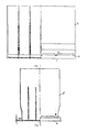
- Fig. 1 das Gehäuse rechts von der Längsseite und links teilweise im Querschnitt;
- Fig. 2 das Gehäuse rechts von der Stirnseite und links teilweise im Querschnitt;
- Fig. 3 die Batterie mit den rechts und links unten auf dem Gehäuse aufgesteckten Leisten und oben mit Batteriedeckel, Haube und Tragegriffen (liegend) von der Längsseite im Querschnitt; mit einem Teilausschnitt B in Fig. 3a und mit einer Front-Teilansicht in Pfeilrichtung C in Fig. 3b;
- Fig. 5 die Haube von der Stirnseite und
- Fig. 6 die Haube von oben mit dem Teilschnitt A in Fig. 6a;
- Fig. 7 den Tragegriff stehend;
- Fig. 8 den Tragegriff liegend und
- Fig. 9 den Tragegriff in Seitenansicht;
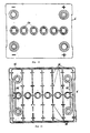
- Fig.10 den Batteriedeckel in Draufsicht und
- Fig.11 den Batteriedeckel von unten;
- Fig.12 die niedrige Befestigungs- oder Steckleiste mit z.B. 8,5 mm Höhe und
- Fig.13 die hohe Befestigungs- bzw. Steckleiste mit z.B. 29 mm Höhe.
- Gemäß Fig. 1 und 2 bildet das Gehäuse 1 mit der außen am unteren Gehäuserand im wesentlichen vollständig umlaufenden Grundleiste 2 eine Einheit. An den Ecken des Gehäuses 1, mit dem die Grundleiste 2 aus einem Stück besteht, kann die Grundleiste 2 auch fehlen. Wichtig ist, daß an allen vier Seiten des Gehäuses 1, den Längsseiten LS und den Stirnseiten SS jeweils Teile der Grundleiste 2 vorhanden sind. Dabei können die auf den Längsseiten LS befindlichen Teile der Grundleiste 2 eine andere Bauhöhe HG aufweisen als die auf den Stirnseiten befindlichen Grundleistenteile. Die Grundleiste 2 mit einer Bauhöhe HG von z.B. 10,5 mm hat drei oder mehrere Vertiefungen 3, durch die die Batterie im Auto mittels Halteorganen befestigt wird. Die Grundleiste 2 steht gemäß Fig. 3a von der Außenwand des Gehäuses 1 seitlich ab und knickt dann nach unten unter Bildung einer nach unten offenen Rinne 2b ab.
- Gemäß Fig. 3 ist die Batterie von der Längsseite LS im Querschnitt dargestellt, wobei z.B. unten rechts auf die Grundleiste 2 die höhere Befestigungsleiste 5 als Steckleiste mit der Höhe H₅ von 29 mm und z.B. unten links die niedrigere Befestigungsleiste 4 wiederum als Steckleiste aufsteckbar sind, welche die Bauhöhe HG der Grundleiste 2 durch Aufstecken bzw. Aufschrauben oder dergleichen Befestigungen von 10,5 mm auf 19,5 mm erhöht. Die auswechselbaren und abnehmbaren Steckleisten 4, 5 sind in Löchern 2a (nur angedeutet) der Grundleiste 2 fixiert.
- Auf dem Batteriedeckel 6 ist die Haube 7 aufgesteckt. Die Tragegriffe 8 sind liegend dargestellt. Gemäß Fig. 4 ist die Batterie im Querschnitt von der Stirnseite SS mit den Tragegriffen 8 einmal in waagrechter und einmal - alternativ - in senkrechter Position aus der abgesetzten in die tragbare Position bringbar.
- Gemäß Fig. 5 ist die Haube 7 von ihrer Längsseite LS abgebildet. Um die Haube 7 auf dem Batteriedeckel 6 verankern zu können, ist sie mit Schnappern 9 in Form hakenförmiger Elemente ausgestattet. Die Haube 7 hat jeweils zwei Öffnungen 10, die den Anschluß der Kabel an jeweils einem Paar der vir Batteriepole 100, 101 ermöglichen. Jeweils ein Batteriepol 100, 101 ist in einem der vier Eckbereiche der in Draufsicht im wesentlichen rechteckigen Batterie angeordnet.
- Gemäß Fig. 6 dienen die Schlitze 11 in der Haube 7 für die Verankerung der Tragegriffe 8 (im Schnitt A-A der Fig. 6 ist die Stirnseite SS der Haube 7 zu sehen). In Fig. 7 ist der Tragegriff 8 längsseitig dargestellt. Die zwei noppenartigen nach außen abstehenden Erhebungen 21 gewährleisten die Verankerung der Tragegriffe 8 in den Schlitzen 11 der Haube 7; sie sind aber nach Bedarf ohne Materialzerstörung auch wieder demontierbar.
- Gemäß Fig. 8 ist der Tragegriff 8 liegend mit den Verstärkungsrippen 13 dargestellt und gemäß Fig. 9 ist der Tragegriff 8 seitlich und teilweise im Schnitt mit den noppenartigen Erhebungen 21 an den Bügeln 12 dargestellt.
- In Fig. 10 mit der Darstellung des Batteriedeckels 6 von oben ist der 4-polige Anschluß (zwei Pluspole 100 und zwei Minus-pole 101 mit den Öffnungen 14 zu sehen, die zum Batterieinhalt führen.
- In Fig. 11 ist der Batteriedeckel 6 von unten abgebildet. Die gleichpoligen Batteriepole 100, 101 sind untereinander mit der Doppelbleibüchse 15 verbunden. Es kann jedoch auch ein Deckel mit nur je einem Plus- und je einem Minus-Pol verwendet werden, welcher - durch Zentrieransätze gehalten - mit einer Außenbrücke in einen Doppelpoldeckel abänderbar ist. Der Batteriedeckel 6 wird im üblichen Spiegelschweißverfahren mit dem Gehäuse 1 verbunden. Um den Batteriedeckel 6 auf dem Gehäuse 1 leicht zentrieren zu können, sind an dem Batteriedeckel nach innen bzw. in Richtung zum Gehäuse 1 und zu dessen Trennwänden 102 oder Rippen gerichtete Zentrierrippen 16 angebracht.
- Gem. Fig. 12 ist die niedrige Steckleiste 4 mit Verstärkungsrippen 17, federelastisch in die Löcher 2a der Grundleiste 2 einschnappbaren und dann wieder aufspreizbaren Aufsteckschnappern 18 und Vertiefungen 3 abgebildet. Mit dem Austeckschnapper 18 wird die Leiste 4 auf der Grundleiste 2 fixiert. Die Vertiefungen 3 dienen dagegen zur Befestigung der Batterie im Auto, Halteorgane greifen in die Vertiefungen 3 ein.
- Gemäß Fig. 13 ist die höhere Steckleiste 5 mit Verstärkungsrippen 19, entsprechenden Aufsteckschnappern 18 und halbkreisförmigen Einschnitten 20 versehen. Mit dem Aufsteckschnapper 18 wird die Leiste 5 wiederum auf der Grundleiste 2 fixiert; während die halbkreisförmigen Einschnitte 20 wie die Vertiefungen 3 die einfache Montage der Batterie im Auto ermöglichen.
- Wenn die Universalbatterie zum Beispiel in ein VW-Auto montiert wird, wird auf die Grundleiste 2 längsseits, d.h. auf beiden Längsseiten LS des Gehäuses 1 die niedrige Steckleiste 4 aufgesteckt.
- Beim Montieren der Universalbatterie in ein Volvo-Auto wird auf die Grundleiste 2 dagegen auf beiden Stirnseiten SS des Gehäuses 1 die höhere Steckleiste 5 aufgesteckt.
- Will man dagegen die Universalbatterie in ein Mazda-Auto einbauen, so bleiben auf der Haube 7 die Tragegriffe 8 aufgesteckt, so daß die Batterie mit dem Spannrahmen im Auto befestigt werden kann.
- In einem Ford-Auto kann die Batterie mit der Grundleiste 2 unmittelbar montiert werden, ohne daß zusätzliche insb. als Steckleisten ausgebildete Befestigungsleisten 4,5 erforderlich sind.
- Die Batterie-Anschlußkabel sind bei manchen Autotypen sehr kurz. Wenn z.B. ein solches Auto für Pluspol 101 "rechts" ausgelegt ist, kann eine Batterie mit Pluspol 101 "links" nicht eingebaut werden. Dieses Problem wurde bei der Universalbatterie so gelöst, daß die vier Pole 100, 101 durch Drehen der Batterie um 180° mit jedem Kabel angeschlossen werden können, da jeweils zwei Batteriepole derselben Polung an der gleichen Seite der Batterie im Abstand voneinander angeordnet sind.
- Die Haube mit dem Tragegriffen ist bei einigen Autotypen zwar nicht erforderlich, diese Elemente können aber dennoch zum Transport der Batterie verwendet werden. Die als "Hohlprofile" ausgebildeten Tragegriffe ergeben einen ausgezeichneten Tragekomfort und sind bei einigen Autotypen als Zwischenelement zum Spannrahmen vorhanden. Die Haube schützt den Batteriedeckel vor Verschmutzung und die Batterie vor eventuellen Kurzschlüssen.
- Diese Universalbatterie kann aus Kunststoffen oder Elastomeren hergestellt sein.
Claims (8)
dadurch gekennzeichnet,
daß die Halteleiste als eine Grundleiste (2) ausgebildet ist, welche an die Längsseiten (LS) und Stirnseiten (SS) des Gehäuses (1) anschließt und zum Aufstecken, Aufklemmen oder dergl. Befestigen von Befestigungsleisten (4, 5) dient.
dadurch gekennzeichnet,
daß die Tragegriffe (8) an einer Haube (7) anlenkbar sind, die am Batteriedeckel (6) verankerbar ist.
dadurch gekennzeichnet,
daß die Befestigungsleisten (4, 5) Vertiefungen (3) und/oder Ein- oder Ausschnitte (20), Verstärkungsrippen (17, 19) und zum Befestigen auf der Grundleiste (2) dienende Aufsteckorgane (18) aufweist.
dadurch gekennzeichnet,
daß Befestigungsleisten (4, 5) unterschiedlicher Bauhöhe (H₄, H₅) verwendet sind.
dadurch gekennzeichnet,
daß die Haube (7) mit Schnappern (9) zum Verankern am Batteriedeckel (6), mit Öffnungen (10) für Kabel und mit Schlitzen (11) für die Tragegriffe (8) versehen ist.
dadurch gekennzeichnet,
daß die Tragegriffe (8) mit Verstärkungsrippen (13) und mit noppenartigen Erhebungen (21) versehen sind.
dadurch gekennzeichnet,
daß die Grundleiste (2) außen am unteren Gehäuserand um das Gehäuse (1) im wesentlichen vollständig umläuft und mit dem Gehäuse (1) einstückig ausgebildet ist.
dadurch gekennzeichnet,
daß die Grundleiste (2) an den Ecken des Gehäuses (1) fehlt.
Priority Applications (1)
| Application Number | Priority Date | Filing Date | Title |
|---|---|---|---|
| AT88102373T ATE94690T1 (de) | 1987-03-02 | 1988-02-18 | Universalbatterie. |
Applications Claiming Priority (2)
| Application Number | Priority Date | Filing Date | Title |
|---|---|---|---|
| DE3706653 | 1987-03-02 | ||
| DE19873706653 DE3706653A1 (de) | 1987-03-02 | 1987-03-02 | Universalbatterie |
Publications (2)
| Publication Number | Publication Date |
|---|---|
| EP0280964A1 true EP0280964A1 (de) | 1988-09-07 |
| EP0280964B1 EP0280964B1 (de) | 1993-09-15 |
Family
ID=6322088
Family Applications (1)
| Application Number | Title | Priority Date | Filing Date |
|---|---|---|---|
| EP88102373A Expired - Lifetime EP0280964B1 (de) | 1987-03-02 | 1988-02-18 | Universalbatterie |
Country Status (3)
| Country | Link |
|---|---|
| EP (1) | EP0280964B1 (de) |
| AT (1) | ATE94690T1 (de) |
| DE (1) | DE3706653A1 (de) |
Cited By (1)
| Publication number | Priority date | Publication date | Assignee | Title |
|---|---|---|---|---|
| EP0798792A1 (de) * | 1996-03-27 | 1997-10-01 | Yuasa Automotive Batteries (Europe) Ltd. | Batteriedeckel |
Citations (10)
| Publication number | Priority date | Publication date | Assignee | Title |
|---|---|---|---|---|
| US3093515A (en) * | 1960-05-31 | 1963-06-11 | Stauffer Chemical Co | Battery case |
| DE2422360A1 (de) * | 1973-05-11 | 1974-11-21 | Tudor Ab | Tragvorrichtung fuer elektrische batterien |
| FR2348581A1 (fr) * | 1976-04-14 | 1977-11-10 | Hoppecke Zoellner Sohn Accu | Accumulateur au plomb |
| DE2741145B1 (de) * | 1977-09-13 | 1978-09-07 | Sonnenschein Accumulatoren | Tragvorrichtung fuer einen Akkumulator |
| GB2120004A (en) * | 1982-03-23 | 1983-11-23 | Lucas Ind Plc | Electric storage battery installation and battery clamp for use therein |
| GB2121233A (en) * | 1982-05-19 | 1983-12-14 | Chloride Group Plc | Battery case and adapters |
| FR2530871A1 (fr) * | 1982-07-20 | 1984-01-27 | Fiat Auto Spa | Accumulateur pour vehicule automobile |
| EP0132949A1 (de) * | 1983-07-01 | 1985-02-13 | Globe-Union Inc. | Akkumulatorbatteriekonstruktion |
| US4693949A (en) * | 1985-08-12 | 1987-09-15 | Douglas Battery Manufacturing Co. | Storage battery housing |
| EP0210317B1 (de) * | 1985-07-22 | 1991-02-06 | Sociedad Espanola Del Acumulador Tudor, S.A. | Elektrische Akkumulatorenbatterie |
Family Cites Families (3)
| Publication number | Priority date | Publication date | Assignee | Title |
|---|---|---|---|---|
| DE7606300U1 (de) * | 1976-03-02 | 1977-08-25 | Varta Batterie Ag, 3000 Hannover | Elektrischer akkumulator, insbesondere starterbatterie |
| ES239695Y (es) * | 1978-11-24 | 1979-05-16 | Tapa para acumuladores electricos | |
| GB2047948B (en) * | 1979-04-23 | 1983-03-16 | Chloride Group Ltd | Electric storage batteries |
-
1987
- 1987-03-02 DE DE19873706653 patent/DE3706653A1/de not_active Withdrawn
-
1988
- 1988-02-18 EP EP88102373A patent/EP0280964B1/de not_active Expired - Lifetime
- 1988-02-18 AT AT88102373T patent/ATE94690T1/de active
Patent Citations (10)
| Publication number | Priority date | Publication date | Assignee | Title |
|---|---|---|---|---|
| US3093515A (en) * | 1960-05-31 | 1963-06-11 | Stauffer Chemical Co | Battery case |
| DE2422360A1 (de) * | 1973-05-11 | 1974-11-21 | Tudor Ab | Tragvorrichtung fuer elektrische batterien |
| FR2348581A1 (fr) * | 1976-04-14 | 1977-11-10 | Hoppecke Zoellner Sohn Accu | Accumulateur au plomb |
| DE2741145B1 (de) * | 1977-09-13 | 1978-09-07 | Sonnenschein Accumulatoren | Tragvorrichtung fuer einen Akkumulator |
| GB2120004A (en) * | 1982-03-23 | 1983-11-23 | Lucas Ind Plc | Electric storage battery installation and battery clamp for use therein |
| GB2121233A (en) * | 1982-05-19 | 1983-12-14 | Chloride Group Plc | Battery case and adapters |
| FR2530871A1 (fr) * | 1982-07-20 | 1984-01-27 | Fiat Auto Spa | Accumulateur pour vehicule automobile |
| EP0132949A1 (de) * | 1983-07-01 | 1985-02-13 | Globe-Union Inc. | Akkumulatorbatteriekonstruktion |
| EP0210317B1 (de) * | 1985-07-22 | 1991-02-06 | Sociedad Espanola Del Acumulador Tudor, S.A. | Elektrische Akkumulatorenbatterie |
| US4693949A (en) * | 1985-08-12 | 1987-09-15 | Douglas Battery Manufacturing Co. | Storage battery housing |
Non-Patent Citations (1)
| Title |
|---|
| ENGINEERING, Band 223, Nr. 11, November 1983, Seiten 894-896, London, GB; "Chloride cuts out battery maintenance" * |
Cited By (1)
| Publication number | Priority date | Publication date | Assignee | Title |
|---|---|---|---|---|
| EP0798792A1 (de) * | 1996-03-27 | 1997-10-01 | Yuasa Automotive Batteries (Europe) Ltd. | Batteriedeckel |
Also Published As
| Publication number | Publication date |
|---|---|
| EP0280964B1 (de) | 1993-09-15 |
| ATE94690T1 (de) | 1993-10-15 |
| DE3706653A1 (de) | 1988-09-15 |
Similar Documents
| Publication | Publication Date | Title |
|---|---|---|
| DE60019475T2 (de) | Kabelbaumschaumschutz der über die Kabel einrastet | |
| EP1064707B1 (de) | Rahmengestell für einen schaltschrank | |
| DE69801988T2 (de) | Rahmen für elektrische verdrahtung | |
| DE69210107T2 (de) | Wasserdichte Montagebauweise für Dachplatten und dgl. | |
| EP0813762A1 (de) | Schaltschrank mit schranktür und dachhaube | |
| DE29707571U1 (de) | Anordnung zur Verbindung von zwei Wärmetauschern | |
| DE2609824A1 (de) | Vorrichtung zur befestigung von aufrollbaren markisen | |
| EP0329843A1 (de) | Gehäuse für ein elektrisches Gerät | |
| DE9317739U1 (de) | Kabelverlegungssystem | |
| DE69826601T2 (de) | Elektrische versorgungseinrichtung mit schutzhaube und bewegbarer stromsteckdose | |
| EP0280964B1 (de) | Universalbatterie | |
| DE102020133641B4 (de) | Elektrofahrzeug oder Hybridfahrzeug | |
| DE602005005662T2 (de) | Frontstruktur eines kraftfahrzeuges | |
| DE69407384T2 (de) | Trägervorrichtung für elektrische Geräte | |
| EP0014749A1 (de) | Halterung für ein an einer Wand lösbar befestigtes Gehäuse | |
| DE19814741C1 (de) | Rahmengestell für einen Schaltschrank | |
| DE4111285A1 (de) | Kabelkanal | |
| EP0933853B1 (de) | Träger zur Aufnahme eines Steckdosenblocks auf einem Sockelleistenkanal | |
| DE9418381U1 (de) | Einrichtung zum Erkennen einer Manipulation an einem geschlossenen Sicherungsgehäuse | |
| DE69514547T2 (de) | Einführungsrahmen | |
| DE29703982U1 (de) | Zählerplatzbaugruppe | |
| EP0297089B1 (de) | Schildträger für Reklameschilder, Preisschilder oder dergleichen | |
| DE3406628C2 (de) | ||
| DE9301220U1 (de) | Mehrpolige Steckvorrichtung zur Kontaktierung eines Autoradios | |
| DE3132524C2 (de) | Gerätegehäuse, insbesondere für Elektrozaungeräte |
Legal Events
| Date | Code | Title | Description |
|---|---|---|---|
| PUAI | Public reference made under article 153(3) epc to a published international application that has entered the european phase |
Free format text: ORIGINAL CODE: 0009012 |
|
| AK | Designated contracting states |
Kind code of ref document: A1 Designated state(s): AT BE CH ES FR GB GR IT LI LU NL SE |
|
| 17P | Request for examination filed |
Effective date: 19881006 |
|
| RAP1 | Party data changed (applicant data changed or rights of an application transferred) |
Owner name: GLAHAG BETEILIGUNGS AG Owner name: ELECTRONA S.A. |
|
| 17Q | First examination report despatched |
Effective date: 19910626 |
|
| GRAA | (expected) grant |
Free format text: ORIGINAL CODE: 0009210 |
|
| AK | Designated contracting states |
Kind code of ref document: B1 Designated state(s): AT BE CH ES FR GB GR IT LI LU NL SE |
|
| PG25 | Lapsed in a contracting state [announced via postgrant information from national office to epo] |
Ref country code: IT Free format text: LAPSE BECAUSE OF FAILURE TO SUBMIT A TRANSLATION OF THE DESCRIPTION OR TO PAY THE FEE WITHIN THE PRE;WARNING: LAPSES OF ITALIAN PATENTS WITH EFFECTIVE DATE BEFORE 2007 MAY HAVE OCCURRED AT ANY TIME BEFORE 2007. THE CORRECT EFFECTIVE DATE MAY BE DIFFERENT FROM THE ONE RECORDED.SCRIBED TIME-LIMIT Effective date: 19930915 Ref country code: ES Free format text: THE PATENT HAS BEEN ANNULLED BY A DECISION OF A NATIONAL AUTHORITY Effective date: 19930915 Ref country code: GB Effective date: 19930915 Ref country code: GR Free format text: LAPSE BECAUSE OF FAILURE TO SUBMIT A TRANSLATION OF THE DESCRIPTION OR TO PAY THE FEE WITHIN THE PRESCRIBED TIME-LIMIT Effective date: 19930915 Ref country code: FR Effective date: 19930915 Ref country code: NL Effective date: 19930915 Ref country code: SE Effective date: 19930915 Ref country code: BE Effective date: 19930915 |
|
| REF | Corresponds to: |
Ref document number: 94690 Country of ref document: AT Date of ref document: 19931015 Kind code of ref document: T |
|
| EN | Fr: translation not filed | ||
| PG25 | Lapsed in a contracting state [announced via postgrant information from national office to epo] |
Ref country code: AT Effective date: 19940218 |
|
| PG25 | Lapsed in a contracting state [announced via postgrant information from national office to epo] |
Ref country code: LU Free format text: LAPSE BECAUSE OF NON-PAYMENT OF DUE FEES Effective date: 19940228 |
|
| NLV1 | Nl: lapsed or annulled due to failure to fulfill the requirements of art. 29p and 29m of the patents act | ||
| PGFP | Annual fee paid to national office [announced via postgrant information from national office to epo] |
Ref country code: CH Payment date: 19940318 Year of fee payment: 7 |
|
| GBV | Gb: ep patent (uk) treated as always having been void in accordance with gb section 77(7)/1977 [no translation filed] |
Effective date: 19930915 |
|
| PLBE | No opposition filed within time limit |
Free format text: ORIGINAL CODE: 0009261 |
|
| STAA | Information on the status of an ep patent application or granted ep patent |
Free format text: STATUS: NO OPPOSITION FILED WITHIN TIME LIMIT |
|
| 26N | No opposition filed | ||
| PG25 | Lapsed in a contracting state [announced via postgrant information from national office to epo] |
Ref country code: CH Effective date: 19950228 Ref country code: LI Effective date: 19950228 |