EP0280967B1 - Dispositif de sélection d'aiguilles dans des métiers à tricoter, métiers pour la fabrication de chaussettes et de bas et analogues - Google Patents
Dispositif de sélection d'aiguilles dans des métiers à tricoter, métiers pour la fabrication de chaussettes et de bas et analogues Download PDFInfo
- Publication number
- EP0280967B1 EP0280967B1 EP88102423A EP88102423A EP0280967B1 EP 0280967 B1 EP0280967 B1 EP 0280967B1 EP 88102423 A EP88102423 A EP 88102423A EP 88102423 A EP88102423 A EP 88102423A EP 0280967 B1 EP0280967 B1 EP 0280967B1
- Authority
- EP
- European Patent Office
- Prior art keywords
- groove
- selector
- rod
- needle
- needle bed
- Prior art date
- Legal status (The legal status is an assumption and is not a legal conclusion. Google has not performed a legal analysis and makes no representation as to the accuracy of the status listed.)
- Expired - Lifetime
Links
Images

Classifications
-
- D—TEXTILES; PAPER
- D04—BRAIDING; LACE-MAKING; KNITTING; TRIMMINGS; NON-WOVEN FABRICS
- D04B—KNITTING
- D04B15/00—Details of, or auxiliary devices incorporated in, weft knitting machines, restricted to machines of this kind
- D04B15/66—Devices for determining or controlling patterns ; Program-control arrangements
- D04B15/68—Devices for determining or controlling patterns ; Program-control arrangements characterised by the knitting instruments used
Definitions
- the present invention relates to a needle selection device in knitting, sock- and stocking-making machines and the like.
- Devices for the selection of the needles in knitting machines are known.
- said devices generally use selectors arranged below the needles in the grooves defined on the lateral surface of the needle cylinder.
- the selectors are provided, on their side facing towards the outside of the needle cylinder, with at least one heel and are controllably movable from an extracted position, in which said heel protrudes from the related groove to engage with selection cams arranged around the needle cylinder, to a sunk position, in which the heel of the selector is completely accommodated into the related groove so as to not engage with the selection cams.
- These selection cams define guide paths for the heel of the selector engaged therewith when the selection cams are caused to rotate relatively to the needle cylinder.
- the selector By virtue of the movement of the selector heel along the paths of the selection cams, the selector undergoes a longitudinal shift in the related groove which causes it to push the overlying needle to selectively engage with its heel within adapted paths defined by needle cams rigid with the selection cams so as to perform the desired knitting.
- each selector is provided, on the side facing towards the outside of the needle cylinder, with a plurality of heels which are engaged or not by adapted levers or blades to push them in the sunk position or keep them in the extraction position.
- Selection devices which use a stack of levers, superimposed and oscillable by means of electromagnetic actuators from an operative position, in which one of their ends is placed at the level of one of the heels of the selector to push it in sunk position, to an inoperative position, in which the end of the lever is in an intermediate position between the heels of the selectors so as to not interfere therewith and therefore keep the selectors in extraction position.
- drawing drums Mechanical devices are also known, termed drawing drums, which provide the same conditions by moving, by means of pins protruding according to a preset arrangement on a rotating cylinder, the levers towards or away from the axis of the needle cylinder.
- Similar selection devices are also used for the selection of the dial needles in circular knitting machines of the type with cylinder and dial.
- FR-A-2,538,418 is a needle selection device as defined in the precharacterizing part of claim 1.
- the aim of the present invention is to solve the above described problems by providing a device which allows an individual selection of the needles using a reduced number of components, is simple to manufacture and has a modest cost.
- an object of the invention is to provide a device which is simple to actuate and control so as to be operable by an electronic control element with a very simple and reliable program.
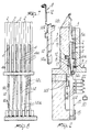
- the device for the selection of the needles according to the invention comprises, for each of the grooves 2, which are defined in the needle bed of a knitting machine or, as in this case, extend on the lateral outer surface of the needle cylinder 3 parallel to its axis, a selector 4 arranged below each needle 5 accommodated in the same groove so as to be slideable in a longitudinal direction, or along a direction which is parallel to the axis of the needle cylinder 3, usually arranged vertically.
- the selector 4 and the needle 5 are retained by adherence in the related groove 2 by means of their known configuration.
- the selector 4 is provided, on its side facing away from the bottom of the groove, with at least one heel 4a which is engageable with selection cams 6 which are arranged around the needle cylinder, or are facing the needle bed of the machine, and which define paths for the heel so that, by rotating the selection cams about the axis of the needle cylinder relatively thereto, the selector is moved along the related groove 2 to act on the overlying needle.
- the needle 5 is in turn provided, on its side facing towards the outside of the needle cylinder, with a heel 5a which is engageable with the needle cams 7 which are also arranged around the needle cylinder and are rigid with the selection cams.
- the needle cams 7 also define paths which are selectively followed by the heel 5a when the needle cams rotate relatively to the needle cylinder. These paths reciprocately actuate the needles along the related grooves to move them for taking the thread at the various feeds or drops of the machines and to form knitting.
- the passage of the heel 5a of the needle from one path to the other of the needle cams is determined by raising or not the related selector, which in turn can change the path followed by its heel, being controllably movable from an extraction position, in which its heel protrudes from the related groove to engage with the related selection cams, to a sunk position, wherein its heel is fully sunk in the related groove so as to not engage with the selection cams.
- the selection device comprises, for each selector: an elastic element 8, which acts on the related selector for its retention in the extraction position, a sinking cam 9 which acts on the selector to push it in the sunk position against the elastic element 8 and engagement means 10 which are engageable with the elastic element 8 when the selector is in sunk position to keep the selector in said position.
- the device according to the invention also comprises actuator means 11 which are arranged after the sinking cam 9, according to the direction of rotation of the selection cams, and which act on the engagement means 10 for their disengagement from the elastic element 8.
- the elastic element 8 is constituted by a small spring 12 interposed between the bottom of the groove 2 and the selector 4.
- Said spring 12 has one of its ends folded and inserted in an adapted recess 13 defined on the bottom of the groove and the other end extending downwardly beyond the lower end of the selector 4.
- the engagement means 10 comprise, for each selector 4, a rod 14 which is arranged aligned with a groove 2 below the selector 4 and has its lower end rigid with a support 15 fixed to the needle cylinder and its upper end movable from an operative position, in which it engages with the lower end of the small spring 12, to an inoperative position, in which it does not interfere with the spring 12.
- the rod 14 is elastically flexible in a plane tangent to the needle cylinder for allowing passage of its upper end from the operative position to the inoperative position and vice versa. To facilitate this flexing, the rod 14 has, in one of its portions, a thickness reduction 14a.
- means 16 for delimiting the flexing of the rod 14 are provided, constituted by abutments 17a defined on a ring 17 fixed around the needle cylinder. More particularly, since for each groove 2 a rod 14 is provided, each rod 14 has, on its side facing the needle cylinder, an expansion 14b which can move, due to the flexing of the rod 14, within a seat defined between two successive abutments 17a (Fig. 10).
- the expansions 14b of two contiguous rods may be placed at mutually different levels and two rings 17 and 18, with respective abutments 17a and 18a, may be provided substantially identical to one another but angularly offset by an angle equal to the spacing angle between two successive grooves of the needle cyliner.
- the sinking cam 9 can be constituted simply by at least one raised portion 19 carried by an annular band 20 rigid with the selection cams.
- two raised portions 19 and 21 are visible which have portions 19a and 21a which extends towards the axis of the needle cylinder and portions 19b and 21b which extend away from the axis of the needle cylinder, considering a direction of rotation of the cams as indicated by the arrow on the annular band 20.
- the actuator means 11 are rigid with the outer surface of the cams, therefore they are rigid with the selection cams, and can be constituted by electromagnets 22 facing the needle cylinder at a protrusion 14c of the rod 14 directed towards the outside of the needle cylinder.
- a plurality of electromagnets 22 may be provided, arranged at different height levels, providing that the protrusions 14c of contiguous rods 14 also be arranged at mutually different levels.
- the actuator means could, however, also be constituted by mechanical devices which controllably contact a rod 14 after the intervention of the sinking cam 9 or by nozzles with controllably deliver a pressurized fluid which strikes the rod 14 causing its flexing.
- the actuator means may be constituted by permanent magnets which are controllably moved closer to the rod 14 to cause its flexing.
- electromagnets, of permanent magnets, or of pressurized-fluid delivery nozzles as schematically shown in figure 15 and indicated at 140, it must be said that the flexing of the rod 14 can be obtained without direct contact with the rod 14.
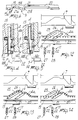
- FIG. 12 illustrates, by way of example, selection cams which define a first rising portion 25 and a second rising portion 26 arranged in succession according to the direction of motion of the selection cams relatively to the needle cylinder indicated by an arrow in said figures.
- the actuator means 11 are divided in a first group 27 and in a second group 28 arranged at the beginning of said rising portions 25,26 and immediately after the raised portions 19 and 21 of sinking cams 9.
- the selection cams 6 should not engage specific selectors 4, it is sufficient not to activate the actuator means 11 intended to act on the corresponding rods 14. In this manner, supposing the selectors 4 are in the extraction position, when the raised portion 19 intervenes on these selectors, the latter are moved to the sunk position and the elastic element 8 is engaged by the rod 14. Thus, as long as the actuator means 11 do not intervene, the selector 4 remains in the sunk position and does not engage the selection cams. In this case the needles 5 which are arranged above said selectors do not perform any knitting or, at least, their heel 5a does not have the possibility of changing path (figure 12).
- the heel 4a of one or more selectors is to be engaged with the first rising portion 25 of the selection cams 6, after the rod 14 has engaged the elastic element 8 by the action of the raised portion 19, one or more of the actuator means 11 of the first group 27, arranged at the beginning of the first rising portion 25, is activated and causes flexing of the rod 14.
- the effect of this flexing is that of obtaining the disengagement of the elastic element which thus moves the selector 4 in operative position with the consequent engagement of its heel with the first rising portion 25.
- Rising of the selector 4 causes the passage of the heel 5a of the needle from one path to another path in the needle cams, according to the various processing requirements.
- the raised portion 21 does not intervene on the selectors which are engaged with the first raised portion 25 since said selectors are in a raised position with respect to the sinking cam (figure 13).
- the actuator means 11 can be actuated by a control element 30, for example of the electronic type, which supervises the various operations of the machine.
- the device according to the invention fully achieves the intended aim, since with a reduced number of actuator means it is able to obtain an individual selection of the needles.
- Another advantage resides in the greater simplicity in manufacture of the selectors with respect to known selectors provided with a plurality of heels.
- the device according to the invention has been described in its application to the needle cylinder of a circular knitting machine, but it may also be applied to the dial of a cylinder and dial circular machine, taking into account the fact that the mentioned grooves, selectors, and therefore rods will be arranged radially.
- the device according to the invention though it has been studied in particular for circular machines, can be used successfully even in rectilinear machines.
- the grooves are defined substantially in a plane, instead of on the lateral surface of a cylinder, and the needle cams with the selection cams move substantially parallel to said plane with a relative motion with respect to the needle bed.
- the rods 14 are laterally flexible in a plane which is parallel to the bottom of the grooves.
- the materials employed, as well as the dimensions, may be any according to the requirements and to the state of the art.
Landscapes
- Engineering & Computer Science (AREA)
- Textile Engineering (AREA)
- Knitting Machines (AREA)
Claims (8)
- Dispositif de sélection des aiguilles dans des métiers à tricoter pour la fabrication des chaussettes et des bas, et l'analogue, comprenant : au moins un sélecteur (4) logé dans une rainure (2) définie dans une fonture d'aiguilles (3) du métier, et agissant sur une aiguille (5) également logée dans ladite rainure au-dessus du sélecteur, ce sélecteur comportant, sur son côté opposé au fond de la rainure, au moins un talon (4a) pouvant coopérer avec des cames de sélection (6) en vis-à-vis de cette fonture d'aiguilles et définissant au moins deux trajets qui peuvent être sélectivement suivis par le talon (4a) pendant un mouvement de ces cames de sélection par rapport à la fonture d'aiguilles, ce sélecteur (4) pouvant être déplacé de manière commandée depuis une position d'extraction, dans laquelle son talon dépasse de la rainure associée (2), jusqu'à une position d'effacement, dans laquelle son talon est enfoncé dans la rainure associée de façon à ne pas interférer avec lesdites cames de sélection, un élément élastique (8) logé dans la rainure (2) et agissant sur le sélecteur (4) pour le retenir dans la position d'extraction, au moins une came d'effacement (9) solidaire des cames de sélection (6) et agissant sur ce sélecteur en antagonisme avec l'élément élastique, des moyens de coopération (10) supportés par la fonture d'aiguilles (3) et coopérant avec le sélecteur en position d'effacement, des moyens d'actionneur (11) solidaires des cames de sélection (6) et disposés après la came d'effacement (9) dans le sens de déplacement de ces cames de sélection par rapport à la fonture d'aiguilles, lesdits moyens d'actionneur (11) pouvant être excités de manière commandée pour dégager les moyens de coopération (10) de l'élément élastique (8), d'où il résulte que le sélecteur (4) retourne dans sa position d'extraction, caractérisé en ce que les moyens de coopération (10) peuvent coopérer avec l'élément élastique (8) lorsque le sélecteur (4) est dans sa position d'effacement et en ce que les moyens de coopération (10) comprennent au moins une tige (14) disposée en alignement avec cette rainure (2) et ayant son extrémité inférieure solidaire de la fonture d'aiguilles (3), cette tige (14) pouvant élastiquement fléchir, sous l'action des moyens d'actionneur (11) dans un plan sensiblement parallèle au fond de la rainure (2) pour permettre à son extrémité supérieure de passer d'une position active, dans laquelle elle coopère avec ladite extrémité de l'élément élastique (8), jusqu'à une position inactive, dans laquelle elle n'interfère pas avec cet élément élastique.
- Dispositif selon la revendication 1, caractérisé en ce qu'il comprend des moyens (16) pour limiter la flexion de la tige (14) dans ledit plan sensiblement parallèle au fond de la rainure.
- Dispositif selon la revendication 1, caractérisé en ce que les moyens d'actionneur (11) comprennent un électro-aimant (22) en vis-à-vis de la fonture d'aiguilles (3) au niveau de la tige (14), cet électro-aimant pouvant être excité de manière commandée pour provoquer la flexion de la tige dans ledit plan sensiblement parallèle au fond de la rainure.
- Dispositif selon la revendication 1, caractérisé en ce que les moyens d'actionneur comprennent des dispositifs mécaniques (140) pouvant coopérer de manière commandée avec ladite tige pour en provoquer la flexion dans ledit plan sensiblement parallèle au fond de la rainure.
- Dispositif selon la revendication 1 ou la revendication 4, caractérisé en ce que les moyens d'actionneur comprennent au moins une buse (140) projetant de manière commandée un fluide sous pression sur ladite tige pour en provoquer la flexion dans ledit plan sensiblement parallèle au fond de la rainure.
- Dispositif selon une ou plusieurs des revendications 1 à 2, caractérisé en ce que les moyens d'actionneur comprennent des aimants permanents (22) pouvant être rapprochés et éloignés de la fonture d'aiguilles pour provoquer la flexion de la tige dans ledit plan sensiblement parallèle au fond de la rainure.
- Dispositif selon la revendication 1 ou la revendication 2, caractérisé en ce que la fonture d'aiguilles (3) comprend un cylindre à aiguilles (3) et en ce que la tige (14) est élastiquement flexible dans un plan sensiblement tangent à ce cylindre à aiguilles.
- Dispositif selon la revendication 2, caractérisé en ce que les moyens (16) pour délimiter la flexion de la tige comprennent des butées (17a) définies sur une couronne (17) solidaire du cylindre à aiguilles (3) constituant la fonture d'aiguilles, ladite couronne définissant au moins une butée pouvant venir en contact avec la tige dans la position active de celle-ci.
Applications Claiming Priority (2)
| Application Number | Priority Date | Filing Date | Title |
|---|---|---|---|
| IT19580/87A IT1202633B (it) | 1987-03-04 | 1987-03-04 | Dispositivo per la selezione degli aghi in macchine per maglieria,calzetteria e simili |
| IT1958087 | 1987-03-04 |
Publications (3)
| Publication Number | Publication Date |
|---|---|
| EP0280967A2 EP0280967A2 (fr) | 1988-09-07 |
| EP0280967A3 EP0280967A3 (en) | 1989-12-13 |
| EP0280967B1 true EP0280967B1 (fr) | 1993-05-19 |
Family
ID=11159210
Family Applications (1)
| Application Number | Title | Priority Date | Filing Date |
|---|---|---|---|
| EP88102423A Expired - Lifetime EP0280967B1 (fr) | 1987-03-04 | 1988-02-19 | Dispositif de sélection d'aiguilles dans des métiers à tricoter, métiers pour la fabrication de chaussettes et de bas et analogues |
Country Status (6)
| Country | Link |
|---|---|
| US (1) | US4884417A (fr) |
| EP (1) | EP0280967B1 (fr) |
| JP (1) | JPS63309654A (fr) |
| DE (2) | DE3881078D1 (fr) |
| ES (1) | ES2040766T3 (fr) |
| IT (1) | IT1202633B (fr) |
Families Citing this family (2)
| Publication number | Priority date | Publication date | Assignee | Title |
|---|---|---|---|---|
| IT1251241B (it) * | 1991-08-23 | 1995-05-05 | Sfim Srl | Macchina per maglieria, o calzetteria, con dispositivo di selezione degli aghi |
| CN105155120B (zh) * | 2015-09-25 | 2017-03-29 | 蔡阿体 | 一种上盘提花选针结构 |
Family Cites Families (10)
| Publication number | Priority date | Publication date | Assignee | Title |
|---|---|---|---|---|
| DE1585215A1 (de) * | 1965-03-06 | 1972-03-30 | Morat Gmbh Franz | Rundstrickmaschine,insbesondere Rundraenderstrickmaschine |
| DE1635968B2 (de) * | 1965-11-02 | 1977-10-06 | Universal Maschinenfabrik Dr. Rudolf Schieber Kg, 7081 Westhausen | Maschine zur herstellung von maschenware |
| US3995451A (en) * | 1971-03-30 | 1976-12-07 | Firma Franz Morat Gmbh | Patterning mechanism |
| GB1393172A (en) * | 1971-04-28 | 1975-05-07 | Schieber Universal Maschf | Method and apparatus for controlling a knitting machine |
| IT1009929B (it) * | 1973-04-25 | 1976-12-20 | Schieber Universal Maschf | Dispositivo per il comando di mac chine di maglieria |
| FR2252431A1 (en) * | 1973-11-23 | 1975-06-20 | Stibbe Monk Development Ltd | Knitting machine needle selector device includes flexible rods - selectively attracted from permanent magnet by electromagnet |
| CH632024A5 (de) * | 1978-09-12 | 1982-09-15 | Steiger Atelier De Constructio | Einzelnadelauswahlvorrichtung fuer flachstrickmaschinen. |
| IT1137166B (it) * | 1981-05-28 | 1986-09-03 | Mecmor Spa | Macchina circolare per maglieria a cilindro e piatto con dispositivo di selezione degli aghi del piatto |
| CH657393A5 (de) * | 1982-12-22 | 1986-08-29 | Dubied & Cie Sa E | Elektromagnetisch gesteuerte nadelauswahlvorrichtung. |
| DE3503219A1 (de) * | 1985-01-31 | 1986-08-07 | Sulzer Morat Gmbh, 7024 Filderstadt | Elektromagnetische mustervorrichtung an einer strickmaschine |
-
1987
- 1987-03-04 IT IT19580/87A patent/IT1202633B/it active
-
1988
- 1988-02-19 ES ES198888102423T patent/ES2040766T3/es not_active Expired - Lifetime
- 1988-02-19 DE DE8888102423A patent/DE3881078D1/de not_active Expired - Fee Related
- 1988-02-19 EP EP88102423A patent/EP0280967B1/fr not_active Expired - Lifetime
- 1988-02-19 DE DE3881078T patent/DE3881078T4/de not_active Expired - Lifetime
- 1988-02-29 US US07/162,395 patent/US4884417A/en not_active Expired - Fee Related
- 1988-03-02 JP JP63047650A patent/JPS63309654A/ja active Pending
Also Published As
| Publication number | Publication date |
|---|---|
| IT1202633B (it) | 1989-02-09 |
| EP0280967A2 (fr) | 1988-09-07 |
| EP0280967A3 (en) | 1989-12-13 |
| DE3881078D1 (de) | 1993-06-24 |
| JPS63309654A (ja) | 1988-12-16 |
| DE3881078T2 (de) | 1993-10-07 |
| US4884417A (en) | 1989-12-05 |
| ES2040766T3 (es) | 1993-11-01 |
| DE3881078T4 (de) | 1995-08-31 |
| IT8719580A0 (it) | 1987-03-04 |
Similar Documents
| Publication | Publication Date | Title |
|---|---|---|
| US11225736B2 (en) | Circular knitting machine and a method for moving the needles of a circular knitting machine | |
| EP0280967B1 (fr) | Dispositif de sélection d'aiguilles dans des métiers à tricoter, métiers pour la fabrication de chaussettes et de bas et analogues | |
| EP0780502A2 (fr) | Métier à tricoter circulaire à cylindre double pour bas ou similaires à commande d'aiguilles améliorée | |
| EP2002043B1 (fr) | Métier à tricoter circulaire à double cylindre pour articles de bonneterie ou autres articles tricotés | |
| EP0379745B1 (fr) | Dispositif de sélection d'aiguilles pour un métier à tricoter circulaire, notamment pour des bas de femmes | |
| CN102108597B (zh) | 在针织机中选择针盘的针的方法和用于实施该方法的针盘 | |
| EP0056131B1 (fr) | Dispositif de sélection d'aiguilles à un métier à tricoter circulaire, en particulier à une tricateuse à bas | |
| US7065989B2 (en) | Sinker selection device in a circular knitting machine | |
| US5960645A (en) | Device for selecting needles in circular stocking knitting machines | |
| EP0328976B1 (fr) | Dispositif de sélection d'aiguilles pour un métier à tricoter | |
| US5072603A (en) | Knitting machine with needle control device for the knitting of pattern stitches | |
| EP0997564A2 (fr) | Cadran ou demie-cadran pour des métiers à tricoter circulaires à cylindre unique, notamment pour la fabrication d'articles tubulaires fermés à un bout longitudunal | |
| US5142886A (en) | Circular knitting machine with a device for repreating the selection of the needles at least at one thread feed | |
| RU2077622C1 (ru) | Кругловязальная машина и устройство для вертикального перемещения игл | |
| US3739601A (en) | Jacquard-pattern arrangement for circular knitting machines | |
| EP4413191B1 (fr) | Chaîne d'entraînement pour éléments de formation de points d'une machine à tricoter circulaire et machine à tricoter circulaire comprenant une telle chaîne d'entraînement | |
| EP4413192B1 (fr) | Chaîne d'entraînement d'éléments de formation de points de machine à tricoter circulaire et machine à tricoter circulaire comprenant une telle chaîne d'entraînement | |
| US5291756A (en) | Knitting machine with needle selecting device | |
| EP0290897A2 (fr) | Dispositif de commande des sélecteurs d'un métier à tricoter circulaire à quatre postes pour des chaussettes et des bas | |
| JPH0633350A (ja) | 丸編機 | |
| US3885404A (en) | Apparatus for patterning knitting machines | |
| US4612785A (en) | Dials for circular knitting machines | |
| EP0957193B1 (fr) | Jeu de cames pour la commande des platines d'abaissement dans des métiers à tricoter circulaires pour la formation de tricot bouclette standard et tricot bouclette sandwich | |
| CS268809B2 (en) | Needle selection device in circular knitting machine | |
| EP3956508A1 (fr) | Métier à tricoter circulaire et procédé de réalisation de points de bouclette dans un métier à tricoter circulaire |
Legal Events
| Date | Code | Title | Description |
|---|---|---|---|
| PUAI | Public reference made under article 153(3) epc to a published international application that has entered the european phase |
Free format text: ORIGINAL CODE: 0009012 |
|
| AK | Designated contracting states |
Kind code of ref document: A2 Designated state(s): CH DE ES FR GB LI SE |
|
| PUAL | Search report despatched |
Free format text: ORIGINAL CODE: 0009013 |
|
| AK | Designated contracting states |
Kind code of ref document: A3 Designated state(s): CH DE ES FR GB LI SE |
|
| 17P | Request for examination filed |
Effective date: 19900111 |
|
| 17Q | First examination report despatched |
Effective date: 19910820 |
|
| GRAA | (expected) grant |
Free format text: ORIGINAL CODE: 0009210 |
|
| AK | Designated contracting states |
Kind code of ref document: B1 Designated state(s): CH DE ES FR GB LI SE |
|
| PG25 | Lapsed in a contracting state [announced via postgrant information from national office to epo] |
Ref country code: SE Effective date: 19930519 Ref country code: FR Effective date: 19930519 |
|
| REF | Corresponds to: |
Ref document number: 3881078 Country of ref document: DE Date of ref document: 19930624 |
|
| EN | Fr: translation not filed | ||
| REG | Reference to a national code |
Ref country code: ES Ref legal event code: FG2A Ref document number: 2040766 Country of ref document: ES Kind code of ref document: T3 |
|
| PGFP | Annual fee paid to national office [announced via postgrant information from national office to epo] |
Ref country code: CH Payment date: 19940218 Year of fee payment: 7 |
|
| PLBE | No opposition filed within time limit |
Free format text: ORIGINAL CODE: 0009261 |
|
| STAA | Information on the status of an ep patent application or granted ep patent |
Free format text: STATUS: NO OPPOSITION FILED WITHIN TIME LIMIT |
|
| 26N | No opposition filed | ||
| PG25 | Lapsed in a contracting state [announced via postgrant information from national office to epo] |
Ref country code: LI Effective date: 19950228 Ref country code: CH Effective date: 19950228 |
|
| PGFP | Annual fee paid to national office [announced via postgrant information from national office to epo] |
Ref country code: GB Payment date: 19960214 Year of fee payment: 9 |
|
| PGFP | Annual fee paid to national office [announced via postgrant information from national office to epo] |
Ref country code: ES Payment date: 19960220 Year of fee payment: 9 |
|
| PGFP | Annual fee paid to national office [announced via postgrant information from national office to epo] |
Ref country code: DE Payment date: 19960227 Year of fee payment: 9 |
|
| PG25 | Lapsed in a contracting state [announced via postgrant information from national office to epo] |
Ref country code: GB Effective date: 19970219 |
|
| PG25 | Lapsed in a contracting state [announced via postgrant information from national office to epo] |
Ref country code: ES Free format text: LAPSE BECAUSE OF NON-PAYMENT OF DUE FEES Effective date: 19970220 |
|
| GBPC | Gb: european patent ceased through non-payment of renewal fee |
Effective date: 19970219 |
|
| PG25 | Lapsed in a contracting state [announced via postgrant information from national office to epo] |
Ref country code: DE Effective date: 19971101 |
|
| REG | Reference to a national code |
Ref country code: ES Ref legal event code: FD2A Effective date: 19990201 |