EP0280983B1 - Scherverfahren und Vorrichtung - Google Patents
Scherverfahren und Vorrichtung Download PDFInfo
- Publication number
- EP0280983B1 EP0280983B1 EP88102550A EP88102550A EP0280983B1 EP 0280983 B1 EP0280983 B1 EP 0280983B1 EP 88102550 A EP88102550 A EP 88102550A EP 88102550 A EP88102550 A EP 88102550A EP 0280983 B1 EP0280983 B1 EP 0280983B1
- Authority
- EP
- European Patent Office
- Prior art keywords
- die
- clamp
- dies
- axis
- movement
- Prior art date
- Legal status (The legal status is an assumption and is not a legal conclusion. Google has not performed a legal analysis and makes no representation as to the accuracy of the status listed.)
- Expired - Lifetime
Links
- 238000010008 shearing Methods 0.000 title claims description 34
- 238000000034 method Methods 0.000 title claims description 8
- 229910052751 metal Inorganic materials 0.000 claims description 5
- 239000002184 metal Substances 0.000 claims description 5
- 230000008602 contraction Effects 0.000 claims description 3
- 239000004411 aluminium Substances 0.000 abstract description 3
- 229910052782 aluminium Inorganic materials 0.000 abstract description 3
- XAGFODPZIPBFFR-UHFFFAOYSA-N aluminium Chemical compound [Al] XAGFODPZIPBFFR-UHFFFAOYSA-N 0.000 abstract description 3
- 230000006835 compression Effects 0.000 description 1
- 238000007906 compression Methods 0.000 description 1
- 238000010276 construction Methods 0.000 description 1
- 239000013536 elastomeric material Substances 0.000 description 1
- 238000001125 extrusion Methods 0.000 description 1
- 238000010438 heat treatment Methods 0.000 description 1
- 238000003780 insertion Methods 0.000 description 1
- 230000037431 insertion Effects 0.000 description 1
- 239000000463 material Substances 0.000 description 1
- 238000000926 separation method Methods 0.000 description 1
Images
Classifications
-
- B—PERFORMING OPERATIONS; TRANSPORTING
- B23—MACHINE TOOLS; METAL-WORKING NOT OTHERWISE PROVIDED FOR
- B23D—PLANING; SLOTTING; SHEARING; BROACHING; SAWING; FILING; SCRAPING; LIKE OPERATIONS FOR WORKING METAL BY REMOVING MATERIAL, NOT OTHERWISE PROVIDED FOR
- B23D23/00—Machines or devices for shearing or cutting profiled stock
-
- B—PERFORMING OPERATIONS; TRANSPORTING
- B23—MACHINE TOOLS; METAL-WORKING NOT OTHERWISE PROVIDED FOR
- B23D—PLANING; SLOTTING; SHEARING; BROACHING; SAWING; FILING; SCRAPING; LIKE OPERATIONS FOR WORKING METAL BY REMOVING MATERIAL, NOT OTHERWISE PROVIDED FOR
- B23D33/00—Accessories for shearing machines or shearing devices
- B23D33/08—Press-pads; Counter-bases; Hold-down devices
-
- Y—GENERAL TAGGING OF NEW TECHNOLOGICAL DEVELOPMENTS; GENERAL TAGGING OF CROSS-SECTIONAL TECHNOLOGIES SPANNING OVER SEVERAL SECTIONS OF THE IPC; TECHNICAL SUBJECTS COVERED BY FORMER USPC CROSS-REFERENCE ART COLLECTIONS [XRACs] AND DIGESTS
- Y10—TECHNICAL SUBJECTS COVERED BY FORMER USPC
- Y10T—TECHNICAL SUBJECTS COVERED BY FORMER US CLASSIFICATION
- Y10T83/00—Cutting
- Y10T83/04—Processes
- Y10T83/0448—With subsequent handling [i.e., of product]
-
- Y—GENERAL TAGGING OF NEW TECHNOLOGICAL DEVELOPMENTS; GENERAL TAGGING OF CROSS-SECTIONAL TECHNOLOGIES SPANNING OVER SEVERAL SECTIONS OF THE IPC; TECHNICAL SUBJECTS COVERED BY FORMER USPC CROSS-REFERENCE ART COLLECTIONS [XRACs] AND DIGESTS
- Y10—TECHNICAL SUBJECTS COVERED BY FORMER USPC
- Y10T—TECHNICAL SUBJECTS COVERED BY FORMER US CLASSIFICATION
- Y10T83/00—Cutting
- Y10T83/202—With product handling means
- Y10T83/2092—Means to move, guide, or permit free fall or flight of product
- Y10T83/2096—Means to move product out of contact with tool
- Y10T83/2122—By ejector within a hollow cutter
-
- Y—GENERAL TAGGING OF NEW TECHNOLOGICAL DEVELOPMENTS; GENERAL TAGGING OF CROSS-SECTIONAL TECHNOLOGIES SPANNING OVER SEVERAL SECTIONS OF THE IPC; TECHNICAL SUBJECTS COVERED BY FORMER USPC CROSS-REFERENCE ART COLLECTIONS [XRACs] AND DIGESTS
- Y10—TECHNICAL SUBJECTS COVERED BY FORMER USPC
- Y10T—TECHNICAL SUBJECTS COVERED BY FORMER US CLASSIFICATION
- Y10T83/00—Cutting
- Y10T83/404—By means to misalign aligned apertured tools
- Y10T83/412—Rectilinear relative movement only
-
- Y—GENERAL TAGGING OF NEW TECHNOLOGICAL DEVELOPMENTS; GENERAL TAGGING OF CROSS-SECTIONAL TECHNOLOGIES SPANNING OVER SEVERAL SECTIONS OF THE IPC; TECHNICAL SUBJECTS COVERED BY FORMER USPC CROSS-REFERENCE ART COLLECTIONS [XRACs] AND DIGESTS
- Y10—TECHNICAL SUBJECTS COVERED BY FORMER USPC
- Y10T—TECHNICAL SUBJECTS COVERED BY FORMER US CLASSIFICATION
- Y10T83/00—Cutting
- Y10T83/748—With work immobilizer
- Y10T83/7487—Means to clamp work
- Y10T83/7493—Combined with, peculiarly related to, other element
- Y10T83/7513—Tool or tool support on movable clamp jaw
-
- Y—GENERAL TAGGING OF NEW TECHNOLOGICAL DEVELOPMENTS; GENERAL TAGGING OF CROSS-SECTIONAL TECHNOLOGIES SPANNING OVER SEVERAL SECTIONS OF THE IPC; TECHNICAL SUBJECTS COVERED BY FORMER USPC CROSS-REFERENCE ART COLLECTIONS [XRACs] AND DIGESTS
- Y10—TECHNICAL SUBJECTS COVERED BY FORMER USPC
- Y10T—TECHNICAL SUBJECTS COVERED BY FORMER US CLASSIFICATION
- Y10T83/00—Cutting
- Y10T83/869—Means to drive or to guide tool
- Y10T83/8752—Tool moves work to and against cooperating tool
- Y10T83/8753—With means to clamp or bind work to moving tool
Definitions
- the present invention relates to shearing and is primarily concerned with shearing elongated, metal bodies into billets which are to be extruded.
- apparatus for shearing metal rods or wire comprising a pair of juxtaposed, annular dies which undergo relative sliding movement at the interface between the dies to effect shearing of a workpiece. It is propsed to incorporate in one or both of the dies an elastic insert which surrounds the workpiece at a position spaced from the interface between the dies. Between the interface and the insert is a portion of the die against which the insert can be compressed by application of an axially directed force towards the interface. Compression of the insert in this way causes the insert to embrace the workpiece. It is evident that the workpiece must be released from the insert, when the insert is relaxed, and that the insert must accordingly be formed of an elastomeric material. Elastomeric materials are unsuitable for use in the dies of shearing apparatus as disclosed in US-A-4152959 and US-A-4063483, which are used to shear hot metal logs.
- the clamping force exerted on the workpiece by an insert is distributed evenly around the circumference of the workpiece.
- all surface portions of the insert which face towards the axis of the die move in respective directions perpendicular to that axis into firm contact with the surface of the workpiece.
- the present invention provides an alternative approach to clamping of a log in a die of shearing apparatus.
- the clamping action takes place in one direction towards the axis of the die, movement of a clamp portion of the die in this one direction forcing against an opposite portion of the internal surface of the die a body which is to be sheared.
- the direction of the clamping action is parallel to the direction of relative movement of the dies during shearing.
- it is the application of a clamping force to the body in a direction parallel to the shearing direction which is required, rather than the application of force to the body in all directions by means of a clamp which embraces the body.
- a method of shearing an elongated body wherein first and second dies are mutually aligned, the body is introduced into the dies, there being a clearance between the body and the first die at at least one position around a longitudinal axis of the body and there being a clearance between the body and the second die at at least one position around a longitudinal axis of the body, at least the first die is then contracted, the body is sheared by relative movement of the dies and the first die is subsequently expanded is characterised in that contraction of the first die includes movement of a clamp portion of the internal surface of the die towards an opposite portion of the internal surface of the die to clamp the body in the first die, the direction of said movement of the clamp portion towards the opposite portion of the internal surface being parallel to the direction of relative movement of the dies during shearing.
- the first die is preferably contracted and expanded also in a direction transverse to the direction of relative movement of the dies for shearing. Contraction of the first die in said transverse direction prior to shearing limits the expansion of the body in the transverse direction which is caused by shearing. If the first die is always contracted to the same size, the same limits will be imposed on transverse expansion of successive logs having respective diameters which differ.
- the second die also may be expanded prior to longitudinal movement of the body and then contracted, in at least the direction of relative movement of the dies, prior to shearing.
- an apparatus suitable for shearing elongated metal bodies comprising first and second juxtaposed dies which receive a body to be sheared and which undergo relative movement to shear the body
- the first die is an assembly comprising a pair of opposite die members presenting respective contact faces for engagement with the body received by the die and the die members are movable towards and away from each other characterised in that said assembly further comprises a clamp, presenting a respective contact face for engagement with the body received by the die and in that the clamp is movable towards and away from the axis of the first die independently of said members.
- a plane which is perpendicular to the first die axis intersects each of said contact surfaces.
- the contact surfaces of the die members and of the clamp may all extend substantially to the interface between the first and second dies.
- each of the die members preferably subtends at the axis of the first die an angle which is within the range 90° to 160°.
- each of the die members preferably includes a portion which is substantially parallel to the direction of movement of the die members towards and away from each other. In a case where this direction is horizontal, such a portion will remain at the same level during movement of the die members and is therefore able to support the body to be sheared at substantially the same level when the die members are moved apart and when the die members are moved towards each other.
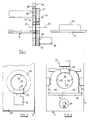
- the apparatus illustrated in the drawing is intended for use in dividing a heated log 10 of aluminium into billets.
- the log typically has a diameter in the region of 150-200 mm and a length of several metres.
- the apparatus comprises a pair of juxtaposed dies 11 and 12 which can be mutually aligned, as shown in Figure 1.
- Conveying means 13 is provided for conveying the log 10 to the dies and passing the log partly through the dies so that one end portion of the log protrudes to the left of the die 12, as viewed in Figure 1 whilst a further part of the log protrudes to the right of the die 11, as viewed in Figure 1.
- the conveying means may be of known construction and includes a furnace (not shown) for heating the log in a known manner.
- the conveying means defines a rectilinear path of travel for the log and an extension of this path passes through the dies 11 and 12 and along a cradle 14 associated with the movable die 12.
- Known means are provided for moving the log along this path. Such means may comprise pushers at opposite ends of the path or driven rollers or a combination of these.
- the die 11 comprises first and second, opposite die members 15 and 16 which are mounted on a frame 17 by guide means 18 arranged for guiding the die members for movement relative to the frame towards and away from each other.
- Hydraulic cylinders 19 and 20 mounted on the frame 17 are arranged for moving the die members 15 and 16 respectively from the positions illustrated in Figure 2, called herein the closed position, in which the die members are in mutual contact at an interface 21 to a position, called the open position, in which there is a gap of several millimetres between the die members 15 and 16.
- the gap between the die members, when in the open position is within the range 2 to 5 millimetre and is more preferably 3 to 4 millimetre.
- the die member 15 has a part-cylindrical contact face 22 which forms a part of the internal surface of the die and contacts the log 10 during use of the apparatus for shearing the log.
- the axis of curvature of the contact face 22 coincides with an axis 23 of the die.
- the contact face subtends at this axis an angle which is less than 180° but greater than 90°. Preferably the angle subtended at the axis 23 by the contact face does not exceed 160°.
- the contact face 22 immediately adjacent to the interface 21, the contact face 22 extends in the direction of movement of the die member 15 relative to the frame 17 from the closed position to the open position. In the example illustrated, this direction is horizontal. Accordingly, the level of the die members 15 and 16 is not changed by movement between the open and closed positions.
- the die member 16 has a part-cylindrical contact face 24 which corresponds to the contact face 22 of the die member 15.
- the contact face 24 has the same radius of curvature as and subtends at the axis 23 the same angle as does the contact face 22.
- the die 11 further comprises a clamp 25 which lies between the die members 15 and 16 at a position diametrically opposite to the interface 21.
- the clamp has a part-cylindrical contact face 26 with a radius of curvature substantially equal to that of the contact face 22 and defining an axis of curvature which can be moved into coincidence with the die axis 23.
- the clamp 25 is mounted on the frame 17 for movement relative thereto towards and away from the axis 23 between an advanced position in which the contact face 26 is spaced from the axis 23 by a distance less than the radius of curvature of the contact face 22, and a retracted position in which the contact face 26 is spaced from the die axis 23 by a distance exceeding the radius of curvature of the contact face 22.
- a piston and cylinder unit 27 is provided for moving the clamp relative to the frame and guide means is provided for guiding the clamp for movement relative to the frame along a rectilinear path which is perpendicular to the direction of movement of the die members 15 and 16.
- the clamp 25 Adjacent to the contact face 26, the clamp 25 has a width, measured in the direction of movement of the die members 15 and 16, which is equal to the spacing between adjacent parts of these members, when in the closed position. Accordingly, when the die members 15 and 16 are in mutual contact at the interface 21, they are both in contact with the clamp 25. It will be noted that the contact faces 22, 24 and 26 do not overlap each other around the axis 23. Furthermore, each of these contact faces extends substantially the same distance from the interface between the dies 11 and 12 in a direction along the axis 23. The three contact faces lie at the same position along that axis and lie in different directions from the axis.
- the width of the clamp is typically equal to the radius of curvature of the contact face 22.
- the die 12 comprises a die member 28 which is fixedly mounted on a frame 29 and which has a part-cylindrical contact face 30 which presents the major part of the internal face of the die 12, subtending at an axis 31 of that die an angle in excess of 180°.
- the angle subtended by the contact face 30 at the axis 31 preferably exceeds 270°.
- the radius of curvature of the contact face 30 is typically slightly greater than the radius of curvature of the contact face 22 and may be substantially equal to the separation between opposite points on the contact faces 22 and 24 when die members 15 and 16 are in the open position, those points being spaced around the axis 23 90° from the interface 21.
- the die 12 further comprises a clamp 32 having a part-cylindrical contact face 33 which constitutes the remainder of the internal face of the die 12.
- the clamp 32 is mounted on the frame 29 for movement by means of a piston and cylinder unit 34 relative thereto towards and away from the axis 31 from a clamping position in which the clamp is somewhat nearer to that axis than is the contact face 30, to an open position in which the clamp is spaced at least as far from the axis 31 as is the contact face 30.
- the clamp 32 is spaced from the axis 31 in a direction opposite to that in which the clamp 25 is spaced from the axis 23.
- the clamps are movable along mutually parallel paths which, in the example illustrated, are vertical.
- the die 12 is guided for movement relative to the die 11 from the co-axial position illustrated in Figure 1 to a position in which the axis 31 lies below the axis 23.
- the stroke of the movable die 12 may exceed the diameter of the dies.
- a pusher 38 In the frame 29, there is provided a similar opening through which a pusher 38 can be projected to push back from the stationary die 11 the remainder of a log from which a billet has been sheared.
- the pusher 38 also participates in upward and downward movement of the die 12 relative to the die 11.
- the pusher 38 may be mounted in a position aligned with the axis 23.
- the dies 11 and 12 Prior to commencement of a shearing operation, the dies 11 and 12 are moved into co-axial relation.
- the die members 15 and 16 are in the open position, the clamp 25 is withdrawn in a direction away from the axis 23 and the clamp 32 is withdrawn in a direction away from the axis 31.
- the conveying means 13 is then operated to pass a portion of the log 10 through the dies until a predetermined length of the log lies to the left of the interface between the dies 11 and 12, as these are viewed in Figure 1. Whilst the clamp 32 is withdrawn, the lowest part of its contact face 33 lies at the same level as do those parts of the contact faces 22 and 24 which are immediately adjacent to the interface 21. This facilitates insertion of the log through the dies.
- the radius of curvature of the contact face 22 is selected to ensure that this radius is no less than the radius of the thickest logs which may be required to be sheared. Accordingly, whilst the die members 15 and 16 are in the open position, the log can extend between these with clearances at opposite sides. There is also a clearance between the log and the retracted clamp 25 and clearance between the log and the entire contact face 30. Even in a case where the log is bent or otherwise deformed, there will be sufficient clearance to facilitate movement of the log through the dies without such movement being impeded significantly by contact between the log and the internal faces of the dies.
- the piston and cylinder units 27 and 34 are operated to lower the clamp 25 on to the log and raise the clamp 34 relative to the die member 28.
- the log is thereby clamped against the die members 15 and 16 adjacent to the interface 21 and against the die member 28 at a position diametrically opposite to the clamp 32.
- the cylinders 19 and 20 are then pressurised to return the die members 15 and 16 to the closed position. In a case where the log is of maximum diameter, this will bring the contact faces 22 and 24 into substantially continuous contact with the log. In a case where the log has a smaller diameter, there may remain some clearance between the log and the contact faces 22 and 24.
- An hydraulic shearing ram 39 which acts between the frames 17 and 29 is then operated to move the die 12 downwardly relative to the die 11 and shear the log.
- the maximum pressure is exerted on the uppermost part of the log by the die member 28 and on the lowermost part of the log by the die members 15 and 16 collectively. This tends to tip the log in an anticlockwise direction, as viewed in Figure 1 but such tipping is prevented by the clamp 25 and either or both of the clamp 32 and the cradle 14.
- the pressure exerted on the log by the die members tends to cause an end portion of the log adjacent to the sheared face to spread laterally. Such spreading is limited by the die members 15 and 16.
- the clamp 25 is withdrawn from the log and the die members 15 and 16 are moved apart, so that the remaining portion of the log can be ejected easily from the die 12.
- the clamp 32 is withdrawn from the sheared billet, in order that the billet can be ejected easily from the die 12 onto the cradle 14.
- the stationary die 11 illustrated in Figure 2 may be modified by the provision of a fourth component which is interposed between the die members 15 and 16 and occupies a position diametrically opposite to that of the clamp 25.
- a fourth component which is interposed between the die members 15 and 16 and occupies a position diametrically opposite to that of the clamp 25.
- Such fourth component would present a part of the internal face of the die and would not participate in movement of the die members, when the die is opened.
- the dimensions of the fourth component may be similar to those of the clamp 25.
- the movable die 12 in the particular example described moves vertically to effect shearing of the log, it will be understood that the invention may be applied to shearing apparatus in which the shearing stroke is an horizontal stroke.
- the clamps would be spaced horizontally from the axes of their respective dies and the die members 15 and 16 would move towards and away from each other vertically.
Landscapes
- Engineering & Computer Science (AREA)
- Mechanical Engineering (AREA)
- Extrusion Of Metal (AREA)
- Accessories And Tools For Shearing Machines (AREA)
- Shearing Machines (AREA)
- Processing Of Stones Or Stones Resemblance Materials (AREA)
- Mechanical Treatment Of Semiconductor (AREA)
Claims (11)
- Verfahren zum Scheren eines langgestreckten Körpers (10), bei dem erste und zweite Schneidbacken (11, 12) wechselseitig miteinander ausgerichtet werden, der Körper in die Schneidbacken eingeführt wird, wobei eine lichte Weite zwischen dem Körper und der ersten Schneidbacke an wenigstens einer Stelle um eine Längsachse des Körpers auftritt und wobei eine lichte Weite zwischen dem Körper und der zweiten Schneidbacke an wenigstens einer Stelle um eine Längsachse des Körpers auftritt, wenigstens die erste Schneidbacke (11) zusammengezogen wird, der Körper durch die relative Bewegung der Schneidbacken abgeschert wird und die erste Schneidbacke nachfolgend ausgeweitet wird, dadurch gekennzeichnet, daß das Zusammenziehen der ersten Schneidbacke die Bewegung eines Klemmabschnittes (26) der Innenfläche der Schneidbacke gegen einen gegenüberliegenden Abschnitt der Innenfläche der Schneidbacke zum Einklemmen des Körpers in der ersten Schneidbacke umfaßt, wobei die Richtung der Bewegung des Klemmabschnittes gegen den gegenüberliegenden Abschnitt der Innenfläche parallel zur Richtung der relativen Bewegung der Schneidbacken während des Scherens ist.
- Verfahren nach Anspruch 1, bei dem die Bewegung des Klemmabschnittes unabhängig von den jeweiligen Positionen anderer Abschnitte der Innenfläche der Schneidbacke ist, welche an derselben Position entlang der Achse liegen wie der Klemmabschnitt, wodurch die auf den Körper durch den Klemmabschnitt und den gegenüberliegenden Abschnitt der Innenfläche der Schneidbacke ausgeübten Kräfte im wesentlichen vollständig in entgegengesetzte Richtungen parallel zur Richtung der relativen Bewegung der Schneidbacken während des Scherens ausgeübt werden.
- Verfahren nach Anspruch 2, bei dem die erste Schneidbacke (11) ebenfalls in eine Richtung quer zur Richtung der relativen Bewegung der Schneidbacken zum Scheren zusammengezogen und ausgeweitet wird.
- Verfahren nach Anspruch 2 oder Anspruch 3, bei dem die zweite Schneidbacke (12) ebenfalls ausgeweitet und zusammengezogen wird, wenigstens in die Richtung der relativen Bewegung der Schneidbacken zum Scheren.
- Vorrichtung, geeignet zum Scheren langgestreckter Metallkörper und mit ersten und zweiten nebeneinander liegenden Schneidbacken (11, 12), die einen zu scherenden Körper (10) aufnehmen und zum Abscheren des Körpers einer relativen Bewegung unterliegen, wobei die erste Schneidbacke eine Anordnung mit einem Paar gegenüberliegender Schneidbackenelemente (15, 16) ist, die jeweilige Kontaktflächen (22, 24) zum Eingriff mit dem Körper, der von der Schneidbacke aufgenommen wird, darstellen, und wobei die Schneidbackenelemente (15, 16) aufeinander zu und voneinander weg bewegbar sind, dadurch gekennzeichnet, daß die Anordnung weiterhin eine Klemme (25) aufweist, die eine entsprechende Kontaktfläche (26) zum Eingriff mit dem von der Schneidbacke aufgenommenen Körper darstellt und daß die Klemme auf die Achse zu und weg von der Achse der ersten Schneidbacke unabhängig von den Elementen bewegbar ist.
- Vorrichtung nach Anspruch 5, bei dem die gesamte Klemme (5) auf die Achse zu und von der Achse der ersten Schneidbacke weg entlang eines Weges bewegbar ist, welcher eine Länge hat, die sich in einer Richtung unterschiedlich von den Richtungen der Bewegung der Schneidbackenelemente (15, 16) aufeinander zu und voneinander weg erstreckt.
- Vorrichtung nach Anspruch 6, bei der die Klemme (25) in eine Position bewegbar ist, in welcher sie von der Achse (23) der ersten Schneidbacke um eine Entfernung beabstandet ist, die geringer ist als die minimale Entfernung zwischen der Achse und einem der Schneidbackenelemente (15, 16).
- Vorrichtung nach Anspruch 6 oder Anspruch 7, bei der eine Ebene, die senkrecht zu der Schneidbackenachse (23) ist, jede der Kontaktflächen (22, 24, 26) durchschneidet.
- Vorrichtung nach Anspruch 8, bei der die Kontaktflächen (22, 24, 26) der Schneidbackenelemente und der Klemme sich alle im wesentlichen zu der Übergangsfläche zwischen der ersten und der zweiten Schneidbacke (11, 12) erstrecken.
- Vorrichtung nach einem der Ansprüche 6 bis 9, bei der die Kontaktfläche jedes der Schneidbackenelemente (15, 16) der Achse (23) der ersten Schneidbacke bei einem Winkel in dem Bereich von 90° bis 160° gegenüberliegt.
- Vorrichtung nach einem der Ansprüche 6 bis 10, bei der die Kontaktfläche jeder der Schneidbackenelemente (15, 16) einen Abschnitt umfaßt, welcher im wesentlichen parallel zu der Bewegungsrichtung der Schneidbackenelemente aufeinander zu und voneinander weg ist.
Priority Applications (1)
| Application Number | Priority Date | Filing Date | Title |
|---|---|---|---|
| AT88102550T ATE69568T1 (de) | 1987-03-05 | 1988-02-22 | Scherverfahren und vorrichtung. |
Applications Claiming Priority (2)
| Application Number | Priority Date | Filing Date | Title |
|---|---|---|---|
| GB878705096A GB8705096D0 (en) | 1987-03-05 | 1987-03-05 | Shearing |
| GB8705096 | 1987-03-05 |
Publications (2)
| Publication Number | Publication Date |
|---|---|
| EP0280983A1 EP0280983A1 (de) | 1988-09-07 |
| EP0280983B1 true EP0280983B1 (de) | 1991-11-21 |
Family
ID=10613336
Family Applications (1)
| Application Number | Title | Priority Date | Filing Date |
|---|---|---|---|
| EP88102550A Expired - Lifetime EP0280983B1 (de) | 1987-03-05 | 1988-02-22 | Scherverfahren und Vorrichtung |
Country Status (5)
| Country | Link |
|---|---|
| US (1) | US4846029A (de) |
| EP (1) | EP0280983B1 (de) |
| AT (1) | ATE69568T1 (de) |
| DE (1) | DE3866258D1 (de) |
| GB (1) | GB8705096D0 (de) |
Families Citing this family (6)
| Publication number | Priority date | Publication date | Assignee | Title |
|---|---|---|---|---|
| DE3841584C1 (de) * | 1988-12-09 | 1990-02-01 | Elhaus Industrieanlagen Gmbh, 7703 Rielasingen-Worblingen, De | |
| HU220749B1 (hu) * | 1995-09-05 | 2002-05-28 | Rondex Oy Ltd. | Eljárás alakított fémalkatrész előállítására |
| US5943930A (en) * | 1996-12-23 | 1999-08-31 | Fasske; Wayne C. | Apparatus for shearing multi-walled workpieces |
| US6439089B1 (en) | 1996-12-23 | 2002-08-27 | Shear, Llc | Apparatus for shearing multi-walled workpieces |
| US20020157512A1 (en) * | 2000-09-11 | 2002-10-31 | Fasske Wayne C. | Portable apparatus for shearing multi-walled workpieces |
| ATE410256T1 (de) * | 2003-10-01 | 2008-10-15 | Helmut Schuster | Schneideeinheit für eine schlagschneidevorrichtung |
Family Cites Families (7)
| Publication number | Priority date | Publication date | Assignee | Title |
|---|---|---|---|---|
| FR1589078A (de) * | 1968-07-16 | 1970-03-23 | ||
| AT296729B (de) * | 1969-01-22 | 1972-02-25 | Koho Es Gepipari Miniszterium | Verfahren und Vorrichtung zum spanlosen Zerteilen von Metallstangen oder Metalldrähten |
| DE2604418C2 (de) * | 1976-02-05 | 1982-06-03 | Friedrich Wilhelm Dipl.-Ing. 5600 Wuppertal Elhaus | Barren-Warmschere |
| JPS52103363A (en) * | 1976-02-27 | 1977-08-30 | Ube Industries | Billet cutter |
| SU749578A1 (ru) * | 1977-10-03 | 1980-07-23 | Предприятие П/Я А-1575 | Штамп дл резки труб |
| SU764880A1 (ru) * | 1978-06-07 | 1980-09-23 | Экспериментальный научно-исследовательский институт кузнечно-прессового машиностроения | Ножницы дл резки сортового проката |
| ES499739A0 (es) * | 1980-02-26 | 1982-06-01 | Mecapec Sa | Perfeccionamientos en una cizalla para cortar material en forma de barra. |
-
1987
- 1987-03-05 GB GB878705096A patent/GB8705096D0/en active Pending
-
1988
- 1988-02-19 US US07/157,908 patent/US4846029A/en not_active Expired - Fee Related
- 1988-02-22 EP EP88102550A patent/EP0280983B1/de not_active Expired - Lifetime
- 1988-02-22 AT AT88102550T patent/ATE69568T1/de not_active IP Right Cessation
- 1988-02-22 DE DE8888102550T patent/DE3866258D1/de not_active Expired - Fee Related
Also Published As
| Publication number | Publication date |
|---|---|
| GB8705096D0 (en) | 1987-04-08 |
| DE3866258D1 (de) | 1992-01-02 |
| US4846029A (en) | 1989-07-11 |
| ATE69568T1 (de) | 1991-12-15 |
| EP0280983A1 (de) | 1988-09-07 |
Similar Documents
| Publication | Publication Date | Title |
|---|---|---|
| US3487668A (en) | Shaping and forming articles | |
| EP0280983B1 (de) | Scherverfahren und Vorrichtung | |
| US3736788A (en) | Crimping or swaging apparatus | |
| US5720197A (en) | Crimper assembly | |
| US5062336A (en) | Hot shearing apparatus | |
| CN109396266B (zh) | 一种预锻深折弯模具 | |
| US3754428A (en) | Method and apparatus for severing tubing | |
| US4063483A (en) | Apparatus for severing billets | |
| JPS63132717A (ja) | 金属押出装置 | |
| EP0051554B1 (de) | Rohrpresse | |
| EP0244063A2 (de) | Verfahren und Vorrichtung zum Schneiden von heissen Metallstäben | |
| US20170320115A1 (en) | Method of equal channel angular extrusion | |
| USRE30688E (en) | Extrusion press for indirect extrusion | |
| GB1577292A (en) | Extrusion press for extruding tubes | |
| CA1122446A (en) | Upsetting of tube ends | |
| US3675458A (en) | Hydraulic section-stretching machine | |
| US4757703A (en) | Die apparatus for handling tubing having a radially projecting annular flange | |
| US5247821A (en) | Extruding press and method for its feeding | |
| US20070017267A1 (en) | Apparatus and method for performing a hydroforming process | |
| US4441353A (en) | Clamp mechanism for upsetter | |
| US2778495A (en) | Extrusion press | |
| WO1991004148A1 (en) | Apparatus for compacting scrap metal | |
| US3528269A (en) | Method of extrusion with liquidpressure and means for carrying out the method | |
| SU632427A1 (ru) | Прессовый инструмент дл непрерывного экструдировани заготовок | |
| CN220636095U (zh) | 一种冲床下料用防漏料结构 |
Legal Events
| Date | Code | Title | Description |
|---|---|---|---|
| PUAI | Public reference made under article 153(3) epc to a published international application that has entered the european phase |
Free format text: ORIGINAL CODE: 0009012 |
|
| AK | Designated contracting states |
Kind code of ref document: A1 Designated state(s): AT BE CH DE ES FR GR IT LI LU NL SE |
|
| 17P | Request for examination filed |
Effective date: 19890303 |
|
| 17Q | First examination report despatched |
Effective date: 19900330 |
|
| GRAA | (expected) grant |
Free format text: ORIGINAL CODE: 0009210 |
|
| AK | Designated contracting states |
Kind code of ref document: B1 Designated state(s): AT BE CH DE ES FR GR IT LI LU NL SE |
|
| PG25 | Lapsed in a contracting state [announced via postgrant information from national office to epo] |
Ref country code: IT Free format text: LAPSE BECAUSE OF FAILURE TO SUBMIT A TRANSLATION OF THE DESCRIPTION OR TO PAY THE FEE WITHIN THE PRE;WARNING: LAPSES OF ITALIAN PATENTS WITH EFFECTIVE DATE BEFORE 2007 MAY HAVE OCCURRED AT ANY TIME BEFORE 2007. THE CORRECT EFFECTIVE DATE MAY BE DIFFERENT FROM THE ONE RECORDED.SCRIBED TIME-LIMIT Effective date: 19911121 Ref country code: GR Free format text: LAPSE BECAUSE OF FAILURE TO SUBMIT A TRANSLATION OF THE DESCRIPTION OR TO PAY THE FEE WITHIN THE PRESCRIBED TIME-LIMIT Effective date: 19911121 Ref country code: AT Effective date: 19911121 Ref country code: BE Effective date: 19911121 Ref country code: ES Free format text: THE PATENT HAS BEEN ANNULLED BY A DECISION OF A NATIONAL AUTHORITY Effective date: 19911121 Ref country code: CH Effective date: 19911121 Ref country code: LI Effective date: 19911121 Ref country code: SE Effective date: 19911121 Ref country code: NL Effective date: 19911121 |
|
| REF | Corresponds to: |
Ref document number: 69568 Country of ref document: AT Date of ref document: 19911215 Kind code of ref document: T |
|
| REF | Corresponds to: |
Ref document number: 3866258 Country of ref document: DE Date of ref document: 19920102 |
|
| REG | Reference to a national code |
Ref country code: CH Ref legal event code: PL |
|
| PG25 | Lapsed in a contracting state [announced via postgrant information from national office to epo] |
Ref country code: LU Free format text: LAPSE BECAUSE OF NON-PAYMENT OF DUE FEES Effective date: 19920229 |
|
| EN | Fr: translation not filed | ||
| PG25 | Lapsed in a contracting state [announced via postgrant information from national office to epo] |
Ref country code: FR Effective date: 19920410 |
|
| NLV1 | Nl: lapsed or annulled due to failure to fulfill the requirements of art. 29p and 29m of the patents act | ||
| PLBE | No opposition filed within time limit |
Free format text: ORIGINAL CODE: 0009261 |
|
| STAA | Information on the status of an ep patent application or granted ep patent |
Free format text: STATUS: NO OPPOSITION FILED WITHIN TIME LIMIT |
|
| PG25 | Lapsed in a contracting state [announced via postgrant information from national office to epo] |
Ref country code: DE Effective date: 19921103 |
|
| 26N | No opposition filed | ||
| REG | Reference to a national code |
Ref country code: FR Ref legal event code: ST |