EP0281016B1 - Dispositif à mandrin multiple pour la fabrication de tubes - Google Patents
Dispositif à mandrin multiple pour la fabrication de tubes Download PDFInfo
- Publication number
- EP0281016B1 EP0281016B1 EP88102803A EP88102803A EP0281016B1 EP 0281016 B1 EP0281016 B1 EP 0281016B1 EP 88102803 A EP88102803 A EP 88102803A EP 88102803 A EP88102803 A EP 88102803A EP 0281016 B1 EP0281016 B1 EP 0281016B1
- Authority
- EP
- European Patent Office
- Prior art keywords
- racks
- cores
- machine according
- chuck machine
- chuck
- Prior art date
- Legal status (The legal status is an assumption and is not a legal conclusion. Google has not performed a legal analysis and makes no representation as to the accuracy of the status listed.)
- Expired - Lifetime
Links
- 230000000694 effects Effects 0.000 claims abstract description 5
- 238000010438 heat treatment Methods 0.000 claims abstract description 4
- 230000000284 resting effect Effects 0.000 claims abstract description 4
- 238000004073 vulcanization Methods 0.000 claims description 11
- 238000004804 winding Methods 0.000 claims description 8
- 239000004744 fabric Substances 0.000 claims description 4
- 230000001360 synchronised effect Effects 0.000 claims description 3
- 230000000295 complement effect Effects 0.000 claims 1
- 239000002994 raw material Substances 0.000 claims 1
- 238000000605 extraction Methods 0.000 description 6
- 238000004806 packaging method and process Methods 0.000 description 6
- 238000004519 manufacturing process Methods 0.000 description 5
- 238000000034 method Methods 0.000 description 5
- 239000011347 resin Substances 0.000 description 4
- 229920005989 resin Polymers 0.000 description 4
- 230000008030 elimination Effects 0.000 description 2
- 238000003379 elimination reaction Methods 0.000 description 2
- 238000003780 insertion Methods 0.000 description 2
- 230000037431 insertion Effects 0.000 description 2
- 230000000670 limiting effect Effects 0.000 description 2
- 239000000463 material Substances 0.000 description 2
- 238000007664 blowing Methods 0.000 description 1
- 238000010276 construction Methods 0.000 description 1
- 238000000151 deposition Methods 0.000 description 1
- 239000000835 fiber Substances 0.000 description 1
- 238000009413 insulation Methods 0.000 description 1
- 239000011159 matrix material Substances 0.000 description 1
- 239000004033 plastic Substances 0.000 description 1
- 230000003014 reinforcing effect Effects 0.000 description 1
- 238000005096 rolling process Methods 0.000 description 1
- 238000000926 separation method Methods 0.000 description 1
- 229920001187 thermosetting polymer Polymers 0.000 description 1
- 239000004636 vulcanized rubber Substances 0.000 description 1
Images

Classifications
-
- B—PERFORMING OPERATIONS; TRANSPORTING
- B29—WORKING OF PLASTICS; WORKING OF SUBSTANCES IN A PLASTIC STATE IN GENERAL
- B29D—PRODUCING PARTICULAR ARTICLES FROM PLASTICS OR FROM SUBSTANCES IN A PLASTIC STATE
- B29D23/00—Producing tubular articles
- B29D23/001—Pipes; Pipe joints
-
- B—PERFORMING OPERATIONS; TRANSPORTING
- B29—WORKING OF PLASTICS; WORKING OF SUBSTANCES IN A PLASTIC STATE IN GENERAL
- B29C—SHAPING OR JOINING OF PLASTICS; SHAPING OF MATERIAL IN A PLASTIC STATE, NOT OTHERWISE PROVIDED FOR; AFTER-TREATMENT OF THE SHAPED PRODUCTS, e.g. REPAIRING
- B29C31/00—Handling, e.g. feeding of the material to be shaped, storage of plastics material before moulding; Automation, i.e. automated handling lines in plastics processing plants, e.g. using manipulators or robots
- B29C31/002—Handling tubes, e.g. transferring between shaping stations, loading on mandrels
-
- B—PERFORMING OPERATIONS; TRANSPORTING
- B29—WORKING OF PLASTICS; WORKING OF SUBSTANCES IN A PLASTIC STATE IN GENERAL
- B29C—SHAPING OR JOINING OF PLASTICS; SHAPING OF MATERIAL IN A PLASTIC STATE, NOT OTHERWISE PROVIDED FOR; AFTER-TREATMENT OF THE SHAPED PRODUCTS, e.g. REPAIRING
- B29C35/00—Heating, cooling or curing, e.g. crosslinking or vulcanising; Apparatus therefor
- B29C35/02—Heating or curing, e.g. crosslinking or vulcanizing during moulding, e.g. in a mould
- B29C2035/0211—Heating or curing, e.g. crosslinking or vulcanizing during moulding, e.g. in a mould resistance heating
-
- B—PERFORMING OPERATIONS; TRANSPORTING
- B29—WORKING OF PLASTICS; WORKING OF SUBSTANCES IN A PLASTIC STATE IN GENERAL
- B29K—INDEXING SCHEME ASSOCIATED WITH SUBCLASSES B29B, B29C OR B29D, RELATING TO MOULDING MATERIALS OR TO MATERIALS FOR MOULDS, REINFORCEMENTS, FILLERS OR PREFORMED PARTS, e.g. INSERTS
- B29K2021/00—Use of unspecified rubbers as moulding material
-
- B—PERFORMING OPERATIONS; TRANSPORTING
- B29—WORKING OF PLASTICS; WORKING OF SUBSTANCES IN A PLASTIC STATE IN GENERAL
- B29L—INDEXING SCHEME ASSOCIATED WITH SUBCLASS B29C, RELATING TO PARTICULAR ARTICLES
- B29L2023/00—Tubular articles
- B29L2023/005—Hoses, i.e. flexible
Definitions
- the present invention relates to a multiple-chuck machine for making woven and/or metallic spiral rubber tubes.
- US-A-2 794 481 discloses a method and an apparatus for making fiber reinforced resin tubing by helically winding, either manually or by mechanical means, fibrous strands impregnated with an uncured thermosetting resin on a cylindrical mandrel.
- fixed-position chucks rotate a respective single metallic core supported in a plurality of points with free rollers rigidly associated with a long table.
- tubes metallic or plastic wire-like spirals can be wound.
- the tube still mounted on the metallic core, is removed from the resting table and taken into an autoclave where it is subject to a steam vulcanization process.
- the tube must be removed from the autoclave, unbandaged and moved to an extraction station where it is freed of the core and wound in coils.
- the aim of the present invention is to provide a machine which, by radically modifying the method of producing vulcanized tubes, allows high productive yields with a reduced number of specialized personnel.
- Still another object is to provide a machine where the winding chucks are substantially in the same region where the vulcanization of said product will occur.
- a further object is to provide a machine where no autoclaves for vulcanization are needed.
- Still another object is to provide a multiple machine comprising all the manufacturing steps, which can be operated by a single operator with consequent great savings in costs and space.
- Not least object is to provide a machine which allows the manufacturing of tubes of different types and characteristics without changing the operating conditions.
- a preferred embodiment of the invention provides a machine which allows to execute all the operations of packaging, vulcanization and extraction of the finished product, always operating on the same spot with no movements of the product.
- a multiple-chuck machine for making tubes by helically winding raw meterial on cores, characterized in that it comprises at least one head with multiple chucks which motorizes a plurality of said cores arranged side by side and supported by a plurality of resting racks articulated by means of hinges on a basement and positionable in a synchronous manner by means of actuators, said racks being flanked by a thermally insulated openable table adapted to contain said cores, the heads of said table having each a multiple electric terminal strip for supplying power to said cores so as to determine a rise in their temperature, by Joule effect, for the vulcanization of the raw tubes.
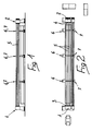
- the machine comprises two heads, respectively indicated by numerals 1 and 2, at least one whereof is motorized and has a plurality of chucks, indicated respectively by numerals 3 and 4, which grip the ends of metallic cylindrical cores 5.
- Said cores 5 are supported by racks 6 and 7 arranged on two parallel lines and conveniently spaced so that said metallic cores 5 are not subject to excessive flexing during processing.
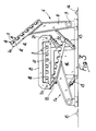
- Each of said racks is composed of a strong metallic arm 8 pivoted at the lower end on a hinge 9 rigidly associated with the basement of the machine or with the floor where the machine is installed.
- Upwardly said metallic arm 8 has a box-like element 10 which has a plurality of grooves 11 each containing a pair of support rollers 12 adapted to support one of the metallic cores 5 on which the rubber tube will be produced.
- the support rollers 12 allow the rolling of the metallic core 5 with low friction and also allow the winding of the spirals of fabric and raw rubber used in the packaging of the tube without hindrance.
- the working position of the element 10, obtained by keeping the metallic arm 8 substantially vertical by means of a double-action piston 13, of the usual, known, construction, called hereinafter piston, is such as to cause the axes of the metallic cores 5 to coincide with the chucks 3 and 4 of the heads, which are articulated to the basement.
- This position arranges the cores 5 at a slant in front of a longitudinal rail 14 on which a carriage moves (not illustrated in the drawings), which carries the operator with the material to be wound in a spiral on said cores 5.
- a table 16 is arranged, composed of a plurality of modules having a length equal to the free interspace between two consecutive racks and having a separation interval substantially equal to the transverse dimensions of a rack 6 or 7 so that the rack, by actuation of its own positioning piston 13, can be lowered to assume the position indicated at 7a in figure 3.
- the table 16 has a thermally insulated support body 17 provided with a plurality of spaced parallel seats 18 with dimensions equivalent to the grooves 11 of the racks.
- said table is closed by a cover 19 which has a double hinge (20,21) on both sides, that is to say along the sides parallel and adjacent to the two rack lines 6 and 7.
- Each of the hinges 20 and 21 can be locked or released depending on whether the cover 19 is opened on one side or on the other to serve one of the two rack lines 6 and 7.
- the cover 19 is also thermally insulated so that when the cores 5 are inserted in the grooves 18 they are in a small size, fully thermally insulated environment.
- the insertion occurs by lowering one of the two racks 6 and 7 together with the head with the chucks after having conveniently opened the cover 19 on the respective side and then depositing the cores 5, on which the tubes have already been packaged with raw rubber, within the seats 18.
- the racks such as the one indicated at 7a in figure 3, are further lowered so as to allow the completion of the insulation by inserting insulating sectors (not illustrated) in the interspace between one module and the other of the table 16.
- the ends of the metallic cores 5 are positioned within two terminal strips (not illustrated) located at the chucks 3 and 4 which will allow the passage of electric current in said cores 5.
- the passage of the current causes, by Joule effect, the heating of said cores to a preset temperature which determines the vulcanization of the raw rubber which has been used to package the tube on said cores 5.
- the cover 19 is again opened and the racks which were in lowered position are raised after opening the terminal strip of electric contacts, achieving the extraction from the table of the set of metallic cores with now vulcanized and finished tubes.
- the machine allows a single operator to perform one or more passes with a rail-mounted carriage arranged to the side of the first rack so as to provide the packaging of a plurality of tubes, individually or simultaneously winding on one or more cores rubber, fabrics or even metallic spirals.
- the cover of the table is opened at the side which allows the insertion of this first plurality of packaged tubes.
- the operator works on the second rack preparing and packaging a second plurality of tubes.
- a first advantage which is apparent in a machine provided according to the invention is the reduced dimensions thereof with respect to the room currently required to execute a similar sequence of operations.
- Materials and dimensions may be chosen in any manner according to the requirements.
Landscapes
- Engineering & Computer Science (AREA)
- Mechanical Engineering (AREA)
- Thermal Sciences (AREA)
- Physics & Mathematics (AREA)
- Health & Medical Sciences (AREA)
- Oral & Maxillofacial Surgery (AREA)
- Robotics (AREA)
- Heating, Cooling, Or Curing Plastics Or The Like In General (AREA)
- Shaping Of Tube Ends By Bending Or Straightening (AREA)
- Metal Extraction Processes (AREA)
- Yarns And Mechanical Finishing Of Yarns Or Ropes (AREA)
- Pipe Accessories (AREA)
- Moulds For Moulding Plastics Or The Like (AREA)
- Rigid Pipes And Flexible Pipes (AREA)
- Making Paper Articles (AREA)
Claims (12)
- Machine à mandrins de serrage multiples permettant de fabriquer des tube en enroulant une matière brute en hélice sur des noyaux, caractérisée en ce qu'elle comprend au moins une tête (1, 2) à mandrins de serrage multiples (3, 4) qui entraînent par moteur plusieurs noyaux (5) disposés côte à côte et portés par plusieurs râteliers de repos (6, 7) articulés au moyen d'articulations (9) sur un socle et agencés de façon à pouvoir être positionnés d'une manière synchrone au moyen d'actionneurs (13), ces râteliers (6, 7) étant adjacents à une table (16) à isolation thermique, agencée de façon à pouvoir être ouverte et adaptée de façon à contenir les noyaux (5), les extrémités de la table comportant chacune une bande formant bornes électriques multiples et servant à alimenter les noyaux (5) en courant de façon à provoquer une élévation de leur température par effet Joule, en vue de la vulcanisation des tubes en matière brute.
- Machine à mandrins de serrage multiples suivant la revendication 1, caractérisée en ce que les râteliers (6, 7) comprennent un bras (8) dont une extrémité inférieure est articulée au moyen de l'articulation (9) sur le socle de la machine, ce bras (8) étant solidaire, vers le haut, d'un élément en forme de caisson (10) qui est pourvu de plusieurs gorges (11) agencées chacune de façon à recevoir l'un des noyaux métalliques (5) en permettant une rotation libre de celui-ci.
- Machine à mandrins de serrage multiples suivant l'une des revendications 1 et 2, caractérisée en ce que, dans les gorges (11), il est prévu au moins deux galets (12) de support libre d'un noyau (5).
- Machine à mandrins de serrage multiples suivant l'une des revendications précédentes, caractérisée en ce que chacun des râteliers (6, 7) est pourvu d'un piston oléodynamique (13), les pistons (13) permettant un mouvement synchrone de tous les râteliers (6, 7) d'une position de travail pratiquement vertical à une seconde position abaissée au-dessous du plan de la table (16), d'une manière simultanée à un déplacement identique des têtes (1, 2).
- Machine à mandrins de serrage multiples suivant l'une des revendications précédentes, caractérisée en ce que le déplacement des râteliers (6, 7) s'effectue sans que les extrémités des noyaux (5) ne soient désengagées des mandrins (3, 4) des têtes (1, 2).
- Machine à mandrins de serrage multiples suivant l'une des revendications précédentes, caractérisée en ce que la table (16) est constituée d'éléments modulaires disposés parallèlement à la rangée de râteliers (6, 7), ces éléments modulaires étant interrompus à l'endroit des râteliers (6, 7) sur une longueur égale à la dimension d'un tel ratelier (6, 7).
- Machine à mandrins de serrage multiples suivant l'une des revendications précédentes, caractérisée en ce que la table (16) comporte des logements longtudinaux (18) destinés à recevoir les noyaux (5) sur lesquels les tubes de matière brute ont été posés, les logements (18) étant pourvus d'un corps d'isolation thermique (17).
- Machine à mandrins de serrage multiples suivant l'une des revendications précédentes, caractérisée en ce que, pendant le mouvement d'abaissement de l'une des rangées de râteliers (6, 7), les râteliers (6, 7) déposent les noyaux (5), sur lesquels les tubes de matière brute ont été posés, à l'intérieur des logements (18) de la table (16).
- Machine à mandrins de serrage multiples suivant l'une des revendications précédentes, caractérisée en ce que la table (16) est pourvue d'un couvercle (19) à isolation thermique qui est articulé sur les deux côtés parallèles aux râteliers (6, 7) au moyen d'articulations (20, 21) agencées de façon à pouvoir être libérées, l'ouverture étant ainsi possible alternativement vers une rangée des râteliers (6, 7) ou vers l'autre.
- Machine à mandrins de serrage multiples suivant l'une des revendications précédentes, caractérisée en ce que les extrémités des noyaux (5), sur lesquels les tubes de matière brute sont enroulés et qui sont en position de retenue à l'intérieur des logements (18) de la table (16), sont insérées dans des bandes formant bornes électriques qui permettent leur alimentation en courant électrique afin de provoquer leur chauffage pareffet Joule.
- Machine à mandrins de serrage multiples suivant l'une des revendications précédentes, caractérisée en ce qu'après l'abaissement d'une rangée de râteliers (6, 7) au-dessous du plan de la table (16), il est prévu des éléments complémentaires d'isolation thermique agencés de façon à fermer les espaces intermédiaires situés entre les modules de la table.
- Machine à mandrins de serrage multiples suivant l'une des revendications précédentes, caractérisée en ce que, parallèlement à chaque rangée de râteliers (6, 7), il est prévu un rail de guidage (14, 15) pour un chariot mobile sur lequel un opérateur exécute l'enroulement de bandes de tissu, de caoutchouc et d'éléments hélicoïdaux de renforcement lorsqu'ils sont nécessaires, sur un ou plusieurs des noyaux (5).
Priority Applications (1)
| Application Number | Priority Date | Filing Date | Title |
|---|---|---|---|
| AT88102803T ATE80576T1 (de) | 1987-03-06 | 1988-02-25 | Maschine mit mehrfach-spannvorrichtung zur rohrherstellung. |
Applications Claiming Priority (2)
| Application Number | Priority Date | Filing Date | Title |
|---|---|---|---|
| IT4154387 | 1987-03-06 | ||
| IT8741543A IT1210350B (it) | 1987-03-06 | 1987-03-06 | Macchina a mandrini multipli per la produzione di tubi in gomma tessuti e/o con spirale metallica. |
Publications (3)
| Publication Number | Publication Date |
|---|---|
| EP0281016A2 EP0281016A2 (fr) | 1988-09-07 |
| EP0281016A3 EP0281016A3 (en) | 1990-01-31 |
| EP0281016B1 true EP0281016B1 (fr) | 1992-09-16 |
Family
ID=11250920
Family Applications (1)
| Application Number | Title | Priority Date | Filing Date |
|---|---|---|---|
| EP88102803A Expired - Lifetime EP0281016B1 (fr) | 1987-03-06 | 1988-02-25 | Dispositif à mandrin multiple pour la fabrication de tubes |
Country Status (6)
| Country | Link |
|---|---|
| EP (1) | EP0281016B1 (fr) |
| AT (1) | ATE80576T1 (fr) |
| CA (1) | CA1305302C (fr) |
| DE (1) | DE3874567D1 (fr) |
| IT (1) | IT1210350B (fr) |
| MX (1) | MX167960B (fr) |
Families Citing this family (3)
| Publication number | Priority date | Publication date | Assignee | Title |
|---|---|---|---|---|
| IT1233543B (it) * | 1989-07-28 | 1992-04-03 | Deregibus A & A Spa | Macchina per la produzione di tubi in gomma vulcanizzata. |
| US5238520A (en) * | 1992-05-27 | 1993-08-24 | Toray Industries, Inc. | Filament winding apparatus |
| IT234874Y1 (it) * | 1994-08-05 | 2000-03-20 | Deregibus A & A Spa | Macchina perfezionata per la produzione di tubi in gomma vulcanizzata |
Family Cites Families (8)
| Publication number | Priority date | Publication date | Assignee | Title |
|---|---|---|---|---|
| US2794481A (en) * | 1955-02-04 | 1957-06-04 | Smith Corp A O | Method and apparatus for making fiber reinforced resin tubing |
| US3202560A (en) * | 1961-01-23 | 1965-08-24 | Rock Island Oil & Refining Co | Process and apparatus for forming glass-reinforced plastic pipe |
| FR2118243A5 (en) * | 1970-12-15 | 1972-07-28 | Ciraud Pierre | Reinforced thermoplastic containers prodn - by hot winding thermoplastic coated filaments |
| US3833979A (en) * | 1973-08-27 | 1974-09-10 | R Seavey | Feed and trim apparatus |
| US4078957A (en) * | 1973-10-03 | 1978-03-14 | Bradt Rexford H | Filament winding apparatus and method |
| IT1151778B (it) * | 1982-05-26 | 1986-12-24 | I T S Srl | Forno per vulcanizzazione elettro-termica di manufatti di gomma |
| US4513900A (en) * | 1983-11-21 | 1985-04-30 | Matlock Gordon E | Wood cross-tie end plating machine |
| EP0151238A3 (fr) * | 1983-12-13 | 1988-03-16 | Messerschmitt-Bölkow-Blohm Gesellschaft mit beschränkter Haftung | Disposition pour la fabrication de pièces tubulaires en matière plastique renforcée par fibres |
-
1987
- 1987-03-06 IT IT8741543A patent/IT1210350B/it active
-
1988
- 1988-02-25 DE DE8888102803T patent/DE3874567D1/de not_active Expired - Lifetime
- 1988-02-25 AT AT88102803T patent/ATE80576T1/de active
- 1988-02-25 EP EP88102803A patent/EP0281016B1/fr not_active Expired - Lifetime
- 1988-03-04 CA CA000560638A patent/CA1305302C/fr not_active Expired - Lifetime
- 1988-03-07 MX MX010674A patent/MX167960B/es unknown
Also Published As
| Publication number | Publication date |
|---|---|
| DE3874567D1 (de) | 1992-10-22 |
| IT8741543A0 (it) | 1987-03-06 |
| CA1305302C (fr) | 1992-07-21 |
| EP0281016A3 (en) | 1990-01-31 |
| ATE80576T1 (de) | 1992-10-15 |
| EP0281016A2 (fr) | 1988-09-07 |
| IT1210350B (it) | 1989-09-14 |
| MX167960B (es) | 1993-04-26 |
Similar Documents
| Publication | Publication Date | Title |
|---|---|---|
| CA1241197A (fr) | Faconnage de panneaux de verre aux formes complexes | |
| CN105690801A (zh) | 一种碳纤维复合材料自动铺丝通用铺放装置 | |
| CN205881686U (zh) | 一种全自动双头空心线圈绕线机 | |
| CN109016282A (zh) | 一种高效液压硫化机组 | |
| EP0281016B1 (fr) | Dispositif à mandrin multiple pour la fabrication de tubes | |
| US3962022A (en) | Method and apparatus for producing a continuous band of rubberized fabric having transversal reinforcing metal elements | |
| US3844701A (en) | Compression molding apparatus | |
| US3187494A (en) | Hose winding apparatus | |
| CN112895542A (zh) | 集成式高效率轮胎硫化中心 | |
| CA1159808A (fr) | Methode et machine pour la fabrication de pieces de revolution faites de matiere tridimensionnelle et dont la generatrice a au moins une partie concave | |
| US4753699A (en) | Method for making hose | |
| WO1989007733A1 (fr) | Appareil de fabrication de goulottes ou cheminees isolantes | |
| WO2024132458A1 (fr) | Système de superposition | |
| EP0410367B1 (fr) | Machine pour la fabrication de tuyau en caoutchouc vulcanisé | |
| JP4623884B2 (ja) | タイヤの製造方法および加硫システム | |
| CN115449993B (zh) | 一种碳纤维织布自动成型生产线 | |
| CN214927296U (zh) | 集成式高效率轮胎硫化中心 | |
| US3127024A (en) | Mandrel stripper for mat winding machine | |
| CN214782477U (zh) | 一种电缆生产加工用外圈皮套编织机 | |
| US3372080A (en) | Machine for the manufacture of flexible bands fitted with hooked elements | |
| US5820727A (en) | Machine particularly for producing vulcanized rubber tubes | |
| SU1323380A1 (ru) | Автоматический манипул тор | |
| EP0466715B1 (fr) | Dispositif de reglage automatique de l'outil multiple dans des machines de coupe a fil chaud | |
| CN110626884A (zh) | 一种氨纶丝自动旋转取丝放丝装置及其取丝放丝方法 | |
| CN223835119U (zh) | 一种带模具装置的液压机 |
Legal Events
| Date | Code | Title | Description |
|---|---|---|---|
| PUAI | Public reference made under article 153(3) epc to a published international application that has entered the european phase |
Free format text: ORIGINAL CODE: 0009012 |
|
| AK | Designated contracting states |
Kind code of ref document: A2 Designated state(s): AT BE CH DE ES FR GB GR LI LU NL SE |
|
| PUAL | Search report despatched |
Free format text: ORIGINAL CODE: 0009013 |
|
| AK | Designated contracting states |
Kind code of ref document: A3 Designated state(s): AT BE CH DE ES FR GB GR LI LU NL SE |
|
| 17P | Request for examination filed |
Effective date: 19900213 |
|
| 17Q | First examination report despatched |
Effective date: 19910122 |
|
| GRAA | (expected) grant |
Free format text: ORIGINAL CODE: 0009210 |
|
| AK | Designated contracting states |
Kind code of ref document: B1 Designated state(s): AT BE CH DE ES FR GB GR LI LU NL SE |
|
| PG25 | Lapsed in a contracting state [announced via postgrant information from national office to epo] |
Ref country code: SE Effective date: 19920916 Ref country code: NL Effective date: 19920916 Ref country code: LI Effective date: 19920916 Ref country code: GR Free format text: LAPSE BECAUSE OF FAILURE TO SUBMIT A TRANSLATION OF THE DESCRIPTION OR TO PAY THE FEE WITHIN THE PRESCRIBED TIME-LIMIT Effective date: 19920916 Ref country code: ES Free format text: THE PATENT HAS BEEN ANNULLED BY A DECISION OF A NATIONAL AUTHORITY Effective date: 19920916 Ref country code: DE Effective date: 19920916 Ref country code: CH Effective date: 19920916 Ref country code: BE Effective date: 19920916 |
|
| REF | Corresponds to: |
Ref document number: 80576 Country of ref document: AT Date of ref document: 19921015 Kind code of ref document: T |
|
| REF | Corresponds to: |
Ref document number: 3874567 Country of ref document: DE Date of ref document: 19921022 |
|
| REG | Reference to a national code |
Ref country code: CH Ref legal event code: PL |
|
| EN | Fr: translation not filed | ||
| PG25 | Lapsed in a contracting state [announced via postgrant information from national office to epo] |
Ref country code: FR Effective date: 19930205 |
|
| NLV1 | Nl: lapsed or annulled due to failure to fulfill the requirements of art. 29p and 29m of the patents act | ||
| PG25 | Lapsed in a contracting state [announced via postgrant information from national office to epo] |
Ref country code: GB Effective date: 19930225 |
|
| PG25 | Lapsed in a contracting state [announced via postgrant information from national office to epo] |
Ref country code: LU Free format text: LAPSE BECAUSE OF NON-PAYMENT OF DUE FEES Effective date: 19930228 |
|
| PLBE | No opposition filed within time limit |
Free format text: ORIGINAL CODE: 0009261 |
|
| STAA | Information on the status of an ep patent application or granted ep patent |
Free format text: STATUS: NO OPPOSITION FILED WITHIN TIME LIMIT |
|
| 26N | No opposition filed | ||
| GBPC | Gb: european patent ceased through non-payment of renewal fee |
Effective date: 19930225 |
|
| REG | Reference to a national code |
Ref country code: FR Ref legal event code: ST |
|
| PGFP | Annual fee paid to national office [announced via postgrant information from national office to epo] |
Ref country code: AT Payment date: 20010227 Year of fee payment: 14 |
|
| PG25 | Lapsed in a contracting state [announced via postgrant information from national office to epo] |
Ref country code: AT Free format text: LAPSE BECAUSE OF NON-PAYMENT OF DUE FEES Effective date: 20020225 |