EP0281020A2 - Dispositif pour l'épuration à l'eau de gaz d'exécution modulaire - Google Patents
Dispositif pour l'épuration à l'eau de gaz d'exécution modulaire Download PDFInfo
- Publication number
- EP0281020A2 EP0281020A2 EP88102831A EP88102831A EP0281020A2 EP 0281020 A2 EP0281020 A2 EP 0281020A2 EP 88102831 A EP88102831 A EP 88102831A EP 88102831 A EP88102831 A EP 88102831A EP 0281020 A2 EP0281020 A2 EP 0281020A2
- Authority
- EP
- European Patent Office
- Prior art keywords
- gas
- washing unit
- module
- foam
- washing
- Prior art date
- Legal status (The legal status is an assumption and is not a legal conclusion. Google has not performed a legal analysis and makes no representation as to the accuracy of the status listed.)
- Withdrawn
Links
Images

Classifications
-
- B—PERFORMING OPERATIONS; TRANSPORTING
- B01—PHYSICAL OR CHEMICAL PROCESSES OR APPARATUS IN GENERAL
- B01D—SEPARATION
- B01D47/00—Separating dispersed particles from gases, air or vapours by liquid as separating agent
- B01D47/04—Separating dispersed particles from gases, air or vapours by liquid as separating agent by passing the gas or air or vapour through foam
-
- B—PERFORMING OPERATIONS; TRANSPORTING
- B01—PHYSICAL OR CHEMICAL PROCESSES OR APPARATUS IN GENERAL
- B01D—SEPARATION
- B01D47/00—Separating dispersed particles from gases, air or vapours by liquid as separating agent
- B01D47/06—Spray cleaning
-
- B—PERFORMING OPERATIONS; TRANSPORTING
- B01—PHYSICAL OR CHEMICAL PROCESSES OR APPARATUS IN GENERAL
- B01D—SEPARATION
- B01D47/00—Separating dispersed particles from gases, air or vapours by liquid as separating agent
- B01D47/12—Washers with plural different washing sections
-
- B—PERFORMING OPERATIONS; TRANSPORTING
- B01—PHYSICAL OR CHEMICAL PROCESSES OR APPARATUS IN GENERAL
- B01D—SEPARATION
- B01D50/00—Combinations of methods or devices for separating particles from gases or vapours
- B01D50/40—Combinations of devices covered by groups B01D45/00 and B01D47/00
Definitions
- the invention relates to a modular design device for the wet cleaning of gas with a horizontal body, the gas inlet side at least one gas washing unit built as a module with tubes arranged transversely to the flow direction of the gas, with a sprinkler provided for the washing liquid and with one among the pipes Pipe attached adjustable distributor for the gas is assigned, and the gas outlet side has a separator built as a module with drip catcher.
- the tubes of the gas scrubbing unit form spaces which act as Venturi nozzles and which cause a suction effect.
- a trough with a device for removing sludge is provided on the bottom of the body.
- corrugated surfaces, nets or other elements can also be provided in the washing unit designed as a module.
- the object underlying the invention is therefore to design the device of the generic type so that the gas can be optimally cleaned in successive, coordinated stages.
- a foam washing unit which is arranged in the horizontal body in the flow direction of the gas after the gas washing unit and is also constructed as a module and which has a grid floor, a foam stabilizer and spray nozzles arranged above it, and by one below arranged the foam washing unit, this connecting to the gas washing unit, formed by a front wall and side walls of the horizontal body and a collector inclined downward towards the gas washing unit, wherein at the deepest point of the inclined bottom a transverse conical drainage channel with washing nozzle is provided.
- module units in a horizontal arrangement depending on the physico-chemical parameters of the gases to be cleaned that pass through them Integrate gas cleaning line with successive module washing zones, in a common horizontal body, which makes maintenance and operation very easy and the material required for production is relatively low.
- the modular construction device shown in FIG. 1 for the wet cleaning of gas consists of a horizontal body 1 which has side walls 2, an end wall 3, observation windows 4, 5 and 6, a cover 7 and an outlet opening 8.
- the horizontal body 1 is preceded by a gas scrubbing unit 13 designed as a module in the form of a cassette.
- a gas scrubbing unit 13 designed as a module in the form of a cassette.
- a set of parallel tubes 10 is arranged, which form spaces acting between them as Venturi nozzles when the flow is transverse.
- a device 11 for sprinkling with a washing liquid is provided above the pipes 10, which device can consist, for example, of a distributor having nozzles.
- the gas washing unit 13 has an upper inlet 9 into which the gas to be cleaned, illustrated by the arrows 27, flows in crosswise direction to the tubes 10 and in cocurrent with the washing liquid.
- An adjustable distributor 14 for the gas is arranged under the tubes 10 of the gas washing unit 13.
- a modular separator 15 is provided on the outlet side and has a drip catcher 16.
- a foam washing unit 17 designed as a module, which consists of a trough 18 with a grid floor 19 and has a foam stabilizer 20 with nozzles 21 arranged above it.
- the foam washing unit 17 is arranged above a bottom 22 which is inclined downward toward the gas washing unit 13 and which, together with the end wall 3 and the side walls 2 of the horizontal body 1, forms a collector 23 which connects the gas washing unit 13 to the foam washing unit 17 and orientates it towards it is.
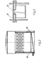
- a transverse conical drain channel 24 is provided, as can be seen from FIG. 2.
- a washing nozzle 25 is provided for the periodic or constant cleaning of the drain channel 24.
- the washing liquid generally water, which flows out of the nozzles of the sprinkler 11 or the nozzles 21 above the foam stabilizer 20, fills the lower part of the horizontal body 1 to form a liquid seal 26.
- the gas to be cleaned supplied in the direction of the arrows 27 passes through the inlet 9 of the gas scrubbing unit 13 together with the scrubbing liquid discharged from the sprinkling device 11 into the spaces between the tubes 10, which act dynamically like Venturi nozzles due to the cross flow of the tubes, which leads to gas suction and contributes to the good mixing of the contaminated gas with the washing liquid.
- the dust particles in the gas to be cleaned are brought into intimate and direct contact on a large surface. As the gas exits the spaces between the tubes 10, its pressure increases and its speed slows down, causing most of the wetted dust particles to agglomerate and to settle on the surface of the liquid closure 26, which consists of washing liquid.
- the gas with the remaining dust particles and impurities is fed through the adjustable distributor 14 and the collector 23 inclined upward towards the foam washing unit 17 to this unit 17, which is designed as a module.
- the agglomeration of some of the dust particles in the gas washing unit 13 prepares the physico-chemical parameters of the gas for the subsequent highly effective cleaning in the foam washing unit 17, which is also designed as a module, this cleaning taking place with an optimal consumption of washing liquid and energy. Due to the dynamic conditions in the venturi spaces between the tubes 10, evaporation processes occur in the hot gases to be cleaned, which leads to a temperature drop to a desired possible limit, which is the prerequisite for a subsequent forced condensation and an effective separation of the residual dust from the gas stream in the foam washing unit 17 built as a module.
- the gas to be cleaned flows from bottom to top through the grid bottom 19 of the tub 18, while washing liquid flows through the nozzles 21 from top to bottom through the grid bottom 19 of the tub 18.
- a layer of movable foam is formed, which is maintained by the foam stabilizer 20.
- the foam stabilizer 20 ensures stable hydrodynamic conditions and thereby influences the state of the movable foam layer very much, a limitation resulting only from the large number of droplets being carried away.
- the cleaned gas emerges from the foam washing unit 17, it flows out through the drip catcher 16 of the separator 15, which is constructed in a modular design, and through the outlet opening 8.
- a pre-cleaning of the gas is achieved by the gas washing unit 13, which enables optimum post-cleaning in the downstream foam washing unit 17 built from a module.
Landscapes
- Chemical & Material Sciences (AREA)
- Chemical Kinetics & Catalysis (AREA)
- Separation Of Particles Using Liquids (AREA)
- Gas Separation By Absorption (AREA)
- Treating Waste Gases (AREA)
Applications Claiming Priority (2)
| Application Number | Priority Date | Filing Date | Title |
|---|---|---|---|
| BG78638/87 | 1987-02-25 | ||
| BG8778638A BG44904A1 (fr) | 1987-02-25 | 1987-02-25 |
Publications (2)
| Publication Number | Publication Date |
|---|---|
| EP0281020A2 true EP0281020A2 (fr) | 1988-09-07 |
| EP0281020A3 EP0281020A3 (fr) | 1989-09-06 |
Family
ID=3918614
Family Applications (1)
| Application Number | Title | Priority Date | Filing Date |
|---|---|---|---|
| EP88102831A Withdrawn EP0281020A3 (fr) | 1987-02-25 | 1988-02-25 | Dispositif pour l'épuration à l'eau de gaz d'exécution modulaire |
Country Status (2)
| Country | Link |
|---|---|
| EP (1) | EP0281020A3 (fr) |
| BG (1) | BG44904A1 (fr) |
Cited By (3)
| Publication number | Priority date | Publication date | Assignee | Title |
|---|---|---|---|---|
| EP0641242A4 (fr) * | 1992-05-19 | 1996-10-02 | Mai Sung Chuan Kit Franklin T | Systemes de filtres pour fumee ou air pollue. |
| CN110639680A (zh) * | 2019-08-24 | 2020-01-03 | 安徽友邦新材料有限公司 | 一种石灰石筛分装置 |
| CN113559646A (zh) * | 2021-09-24 | 2021-10-29 | 徐州众迈节能环保科技有限公司 | 一种介质捕捉自降落式有机废气两级分离装置 |
Family Cites Families (7)
| Publication number | Priority date | Publication date | Assignee | Title |
|---|---|---|---|---|
| AT254834B (de) * | 1963-10-08 | 1967-06-12 | Waagner Biro Ag | Verfahren und Einrichtung zur Ausscheidung von in Gasen feinverteilter Materie |
| DE2231895A1 (de) * | 1971-07-20 | 1973-02-08 | Environeering | Verfahren und einrichtung zum reinigen von verschmutztem gas |
| CH561077A5 (en) * | 1973-10-18 | 1975-04-30 | Capuli Giuseppe | Exhaust fume scrubber - to remove soot and impurities from gas passed through tank of liq via a conical constriction |
| JPS54145371A (en) * | 1978-05-04 | 1979-11-13 | Kureha Chem Ind Co Ltd | Gas-liquid contact device |
| CH639290A5 (en) * | 1979-08-29 | 1983-11-15 | Ciba Geigy Ag | Apparatus for removing gaseous and solid pollutants and mists thereof from a waste gas |
| US4263024A (en) * | 1979-10-10 | 1981-04-21 | Venturmation, Inc. | Air cleaning device |
| US4608064A (en) * | 1985-01-03 | 1986-08-26 | Protectaire Systems Co. | Multi-wash spray booth and method of capturing air borne particles |
-
1987
- 1987-02-25 BG BG8778638A patent/BG44904A1/xx unknown
-
1988
- 1988-02-25 EP EP88102831A patent/EP0281020A3/fr not_active Withdrawn
Cited By (3)
| Publication number | Priority date | Publication date | Assignee | Title |
|---|---|---|---|---|
| EP0641242A4 (fr) * | 1992-05-19 | 1996-10-02 | Mai Sung Chuan Kit Franklin T | Systemes de filtres pour fumee ou air pollue. |
| CN110639680A (zh) * | 2019-08-24 | 2020-01-03 | 安徽友邦新材料有限公司 | 一种石灰石筛分装置 |
| CN113559646A (zh) * | 2021-09-24 | 2021-10-29 | 徐州众迈节能环保科技有限公司 | 一种介质捕捉自降落式有机废气两级分离装置 |
Also Published As
| Publication number | Publication date |
|---|---|
| BG44904A1 (fr) | 1989-03-15 |
| EP0281020A3 (fr) | 1989-09-06 |
Similar Documents
| Publication | Publication Date | Title |
|---|---|---|
| DE2202236C3 (de) | Waschvorrichtung | |
| DE733296C (de) | Verfahren und Vorrichtung zum Zerstoeren von Schaum | |
| EP0820802A2 (fr) | Laveur à plusieures étapes et procédé pour la purification totale de gaz | |
| DE3129812C2 (de) | Verfahren und Vorrichtung zur Gichtgaskühlung | |
| DE69404175T2 (de) | Farbauftrageinrichtung | |
| DE1807327C3 (de) | Vorrichtung zum Abscheiden von Schwebestoffteilchen aus einem Gas | |
| DE4331415C2 (de) | Vorrichtung zur Behandlung eines Gasstromes mit Waschflüssigkeit | |
| DE2301469B2 (fr) | ||
| DE3100004C2 (de) | Waschkolonne | |
| DE3634126C2 (fr) | ||
| DE2753210A1 (de) | Waschvorrichtung | |
| DE1421310B2 (de) | Verfahren und Vorrichtung zum Abscheiden von Staubteilchen aus einem Gasstrom | |
| EP0281020A2 (fr) | Dispositif pour l'épuration à l'eau de gaz d'exécution modulaire | |
| DE2559992B1 (de) | Tropfenabscheider bei einer Vorrichtung zum Kuehlen durch Verdunsten eingespritzter Fluessigkeit | |
| DE2144382C3 (de) | Vorrichtung für die Naßreinigung von Gasen | |
| DE960452C (de) | Vorrichtung zur Vorbereitung der Nassentstaubung von Gasen | |
| DE2726083A1 (de) | Nassreinigungsvorrichtung | |
| DE4105510C1 (en) | Sintering plant where fine heavy metal dust and hazardous gas are removed - has dust removal appts. with electrostatic filter, quench cooler with liq. atomising nozzles, drop separator at gas outlet etc. | |
| DE3341318A1 (de) | Nassabscheider sowie verfahren zur nassabscheidung von in gasen dispergierten schwebestoffen | |
| DE4229736C1 (de) | Verfahren zum Betrieb einer Rauchgasentschwefelungsanlage und Anlage für die Durchführung des Verfahrens | |
| DE2163718B2 (de) | Verfahren und Vorrichtung zum Reinigen staubhaltiger oder durch Schadgasbestandteile verunreinigter Rohgase | |
| DE4345364C2 (de) | Vorrichtung zur Behandlung eines Gasstromes mit Waschflüssigkeit | |
| DE2146747C3 (fr) | ||
| DE1811537A1 (de) | Entstaubungsvorrichtung,insbesondere fuer Lackierkabinen | |
| AT223176B (de) | Naßabscheider |
Legal Events
| Date | Code | Title | Description |
|---|---|---|---|
| PUAI | Public reference made under article 153(3) epc to a published international application that has entered the european phase |
Free format text: ORIGINAL CODE: 0009012 |
|
| AK | Designated contracting states |
Kind code of ref document: A2 Designated state(s): AT BE CH DE ES FR GB IT LI NL SE |
|
| PUAL | Search report despatched |
Free format text: ORIGINAL CODE: 0009013 |
|
| AK | Designated contracting states |
Kind code of ref document: A3 Designated state(s): AT BE CH DE ES FR GB IT LI NL SE |
|
| 17P | Request for examination filed |
Effective date: 19891031 |
|
| 17Q | First examination report despatched |
Effective date: 19910221 |
|
| STAA | Information on the status of an ep patent application or granted ep patent |
Free format text: STATUS: THE APPLICATION HAS BEEN WITHDRAWN |
|
| 18W | Application withdrawn |
Withdrawal date: 19910517 |
|
| R18W | Application withdrawn (corrected) |
Effective date: 19910517 |