EP0281093A2 - Support d'appareil - Google Patents
Support d'appareil Download PDFInfo
- Publication number
- EP0281093A2 EP0281093A2 EP88103149A EP88103149A EP0281093A2 EP 0281093 A2 EP0281093 A2 EP 0281093A2 EP 88103149 A EP88103149 A EP 88103149A EP 88103149 A EP88103149 A EP 88103149A EP 0281093 A2 EP0281093 A2 EP 0281093A2
- Authority
- EP
- European Patent Office
- Prior art keywords
- support
- arm
- support arm
- carrier according
- joint
- Prior art date
- Legal status (The legal status is an assumption and is not a legal conclusion. Google has not performed a legal analysis and makes no representation as to the accuracy of the status listed.)
- Withdrawn
Links
Images


Classifications
-
- F—MECHANICAL ENGINEERING; LIGHTING; HEATING; WEAPONS; BLASTING
- F16—ENGINEERING ELEMENTS AND UNITS; GENERAL MEASURES FOR PRODUCING AND MAINTAINING EFFECTIVE FUNCTIONING OF MACHINES OR INSTALLATIONS; THERMAL INSULATION IN GENERAL
- F16M—FRAMES, CASINGS OR BEDS OF ENGINES, MACHINES OR APPARATUS, NOT SPECIFIC TO ENGINES, MACHINES OR APPARATUS PROVIDED FOR ELSEWHERE; STANDS; SUPPORTS
- F16M11/00—Stands or trestles as supports for apparatus or articles placed thereon ; Stands for scientific apparatus such as gravitational force meters
- F16M11/02—Heads
- F16M11/04—Means for attachment of apparatus; Means allowing adjustment of the apparatus relatively to the stand
- F16M11/06—Means for attachment of apparatus; Means allowing adjustment of the apparatus relatively to the stand allowing pivoting
- F16M11/08—Means for attachment of apparatus; Means allowing adjustment of the apparatus relatively to the stand allowing pivoting around a vertical axis, e.g. panoramic heads
-
- A—HUMAN NECESSITIES
- A47—FURNITURE; DOMESTIC ARTICLES OR APPLIANCES; COFFEE MILLS; SPICE MILLS; SUCTION CLEANERS IN GENERAL
- A47B—TABLES; DESKS; OFFICE FURNITURE; CABINETS; DRAWERS; GENERAL DETAILS OF FURNITURE
- A47B21/00—Tables or desks for office equipment, e.g. typewriters, keyboards
- A47B21/03—Tables or desks for office equipment, e.g. typewriters, keyboards with substantially horizontally extensible or adjustable parts other than drawers, e.g. leaves
- A47B21/0314—Platforms for supporting office equipment
-
- F—MECHANICAL ENGINEERING; LIGHTING; HEATING; WEAPONS; BLASTING
- F16—ENGINEERING ELEMENTS AND UNITS; GENERAL MEASURES FOR PRODUCING AND MAINTAINING EFFECTIVE FUNCTIONING OF MACHINES OR INSTALLATIONS; THERMAL INSULATION IN GENERAL
- F16M—FRAMES, CASINGS OR BEDS OF ENGINES, MACHINES OR APPARATUS, NOT SPECIFIC TO ENGINES, MACHINES OR APPARATUS PROVIDED FOR ELSEWHERE; STANDS; SUPPORTS
- F16M11/00—Stands or trestles as supports for apparatus or articles placed thereon ; Stands for scientific apparatus such as gravitational force meters
- F16M11/20—Undercarriages with or without wheels
- F16M11/2007—Undercarriages with or without wheels comprising means allowing pivoting adjustment
- F16M11/2014—Undercarriages with or without wheels comprising means allowing pivoting adjustment around a vertical axis
-
- F—MECHANICAL ENGINEERING; LIGHTING; HEATING; WEAPONS; BLASTING
- F16—ENGINEERING ELEMENTS AND UNITS; GENERAL MEASURES FOR PRODUCING AND MAINTAINING EFFECTIVE FUNCTIONING OF MACHINES OR INSTALLATIONS; THERMAL INSULATION IN GENERAL
- F16M—FRAMES, CASINGS OR BEDS OF ENGINES, MACHINES OR APPARATUS, NOT SPECIFIC TO ENGINES, MACHINES OR APPARATUS PROVIDED FOR ELSEWHERE; STANDS; SUPPORTS
- F16M11/00—Stands or trestles as supports for apparatus or articles placed thereon ; Stands for scientific apparatus such as gravitational force meters
- F16M11/20—Undercarriages with or without wheels
- F16M11/2092—Undercarriages with or without wheels comprising means allowing depth adjustment, i.e. forward-backward translation of the head relatively to the undercarriage
-
- F—MECHANICAL ENGINEERING; LIGHTING; HEATING; WEAPONS; BLASTING
- F16—ENGINEERING ELEMENTS AND UNITS; GENERAL MEASURES FOR PRODUCING AND MAINTAINING EFFECTIVE FUNCTIONING OF MACHINES OR INSTALLATIONS; THERMAL INSULATION IN GENERAL
- F16M—FRAMES, CASINGS OR BEDS OF ENGINES, MACHINES OR APPARATUS, NOT SPECIFIC TO ENGINES, MACHINES OR APPARATUS PROVIDED FOR ELSEWHERE; STANDS; SUPPORTS
- F16M11/00—Stands or trestles as supports for apparatus or articles placed thereon ; Stands for scientific apparatus such as gravitational force meters
- F16M11/20—Undercarriages with or without wheels
- F16M11/24—Undercarriages with or without wheels changeable in height or length of legs, also for transport only, e.g. by means of tubes screwed into each other
-
- A—HUMAN NECESSITIES
- A47—FURNITURE; DOMESTIC ARTICLES OR APPLIANCES; COFFEE MILLS; SPICE MILLS; SUCTION CLEANERS IN GENERAL
- A47B—TABLES; DESKS; OFFICE FURNITURE; CABINETS; DRAWERS; GENERAL DETAILS OF FURNITURE
- A47B21/00—Tables or desks for office equipment, e.g. typewriters, keyboards
- A47B21/03—Tables or desks for office equipment, e.g. typewriters, keyboards with substantially horizontally extensible or adjustable parts other than drawers, e.g. leaves
- A47B21/0314—Platforms for supporting office equipment
- A47B2021/0321—Keyboard supports
-
- A—HUMAN NECESSITIES
- A47—FURNITURE; DOMESTIC ARTICLES OR APPLIANCES; COFFEE MILLS; SPICE MILLS; SUCTION CLEANERS IN GENERAL
- A47B—TABLES; DESKS; OFFICE FURNITURE; CABINETS; DRAWERS; GENERAL DETAILS OF FURNITURE
- A47B21/00—Tables or desks for office equipment, e.g. typewriters, keyboards
- A47B21/03—Tables or desks for office equipment, e.g. typewriters, keyboards with substantially horizontally extensible or adjustable parts other than drawers, e.g. leaves
- A47B21/0314—Platforms for supporting office equipment
- A47B2021/0364—Keyboard and monitor supports
-
- A—HUMAN NECESSITIES
- A47—FURNITURE; DOMESTIC ARTICLES OR APPLIANCES; COFFEE MILLS; SPICE MILLS; SUCTION CLEANERS IN GENERAL
- A47B—TABLES; DESKS; OFFICE FURNITURE; CABINETS; DRAWERS; GENERAL DETAILS OF FURNITURE
- A47B2210/00—General construction of drawers, guides and guide devices
- A47B2210/15—Keyboard drawers
-
- F—MECHANICAL ENGINEERING; LIGHTING; HEATING; WEAPONS; BLASTING
- F16—ENGINEERING ELEMENTS AND UNITS; GENERAL MEASURES FOR PRODUCING AND MAINTAINING EFFECTIVE FUNCTIONING OF MACHINES OR INSTALLATIONS; THERMAL INSULATION IN GENERAL
- F16M—FRAMES, CASINGS OR BEDS OF ENGINES, MACHINES OR APPARATUS, NOT SPECIFIC TO ENGINES, MACHINES OR APPARATUS PROVIDED FOR ELSEWHERE; STANDS; SUPPORTS
- F16M2200/00—Details of stands or supports
- F16M2200/06—Arms
- F16M2200/068—Arms being part of the undercarriage
Definitions
- the invention relates to a device carrier with a support rotatably mounted about a vertical axis, preferably for a viewing device, and with a support surface arranged on a support arm, in particular for a keyboard, the support surface being changeable in its distance from the axis by longitudinal displacement of the support arm and in its position at the greatest distance from the axis assumes a position which is lowered compared to the position at the smallest distance.
- the bearing surface is rigidly connected to the support arm.
- the usability should be improved.
- This task will solved according to the invention in that the support surface is connected to a support arm via a hinge with a horizontal pivot axis, that the support arm is pivotally connected at its end facing away from the support surface to another arm via a further joint that the further arm and when the further joint of the arm is displaceable in a part of the device support supporting the support, and that a parallel guide is provided for the support surface which keeps the support surface parallel to itself in all displacement positions and pivot positions of the support arm.
- An advantage of the invention is that the support surface always remains parallel to itself and therefore a keyboard remains parallel to itself both in the lowered position for normal operation and in the raised and relatively close to the platen position.
- the keyboard placed on the storage surface cannot easily move by itself.
- the bearing surface is connected to the joint via a third joint with a vertical pivot axis.
- the keyboard which generally has a rectangular base and is arranged with sufficient space so that its front edge is substantially parallel to the front of a device standing on the platen, in particular a screen, around the vertical Axis can be rotated if the keyboard cannot be positioned exactly between the user and the screen due to space constraints.
- a device for limiting the lowering of the support surface with respect to its rest position is provided with the support arm inserted into the part supporting the support plate.
- the parallel guidance is realized by a parallel link handlebar.
- the arm is made of a rigid profile
- the advantage is that the support surface for the keyboard in individual cases, with the position lowered, floats freely either over another work surface (e.g. desk) or laterally on one such a work surface can be arranged, and that nevertheless the actuation of the keyboard is possible without annoying rebounding of the support surface.
- Another advantage of the invention is that in the lowered position, even if the extent of the lowering can be reduced in individual cases by a movable stop compared to the maximum possible extent, the user is generally forced to use the viewing device, in particular a cathode ray beam. Screen to keep a minimum distance, which is useful for occupational safety reasons.
- a vertical column 1 has at its lower end with an attachment device 2, only indicated, for attachment to a base, for example a desk.
- the column 1 has a support part 4, on which a carriage 6 can be displaced in the horizontal direction, from left to right in FIG. 1, on which a support plate 8 extends around a plane perpendicular to the plane of the drawing in FIG. horizontal axis can be tilted.
- the support part 4 is pivotally mounted about a vertical axis by means of the column 1. A in the operating position of the entire device from the support member 4 from obliquely forward (in Fig.
- extending arm 10 is attached at its front end by means of a joint 12 with a pivot axis perpendicular to the plane of FIG. 1 to a part 14 .
- the support arm 10 is pivotally connected to a further arm 18 by means of a further joint 16, which runs parallel to the joint 12.
- the support arm 10 and the further arm 18 have been displaced relative to the support part 4 so far to the right that the support part of the pivoting movement of the support arm 10 downward into the position shown in FIG. 1 opposed no resistance.
- the support arm 10 If the support arm 10 is pivoted upwards into a horizontal position, it can be inserted to the left into the interior of the support part 4, so that the support arm 10 cannot pivot downwards, with the further arm 18 at the rear end in the most retracted position of the support part 4 protrudes, as shown by dash-dotted lines.
- the further arm 18 and the part 14 are connected to one another by a pressure-resistant and tension-proof handlebar which is as long as the distance between the joints, joints 12 and 16 and which runs parallel to the connecting line of the joints 12 and 16.
- a third joint 22 whose pivot axis is perpendicular and thus runs parallel to the pivot axis of the entire device, which is determined by the column 1 .
- a support part 24 is connected, which is provided for placing a keyboard that controls the display on a display device to be placed on the support plate 8. Due to the parallel guidance described above, the support surface 26 of the support member 24 is always kept horizontal. Starting from the position shown in FIG.
- the third hinge 22 rotates the support part 24 about 45 ° to the left and 45 ° to the right. Other swivel angles are also possible.
- the support arm is made of a hollow profile, which has a substantially rectangular cross section, which is pulled inward on two narrow sides, where 4 sliding linings 30 engage in the region of the support part in order to ensure easy displacement.
- the part 24 is seated on a support when the support arm 10 is pivoted down, namely on the top e.g. a desk on which the entire device is mounted.
- a movable stop for example a screw, is provided, which acts in a suitable manner between two of the parts of the handlebar parallelogram which are movable relative to one another (support arm 10, part 14, further arm 18 and the above-mentioned handlebar) in order to move these parts relative to one another limit the desired value.
- the support arm 10 and the other parts are sufficiently stable to support the keyboard so that even when the part 24 is not supported on a solid base that the keyboard does not spring up and down.
- the tragarn 10 consists in the embodiment of light metal; a suitable plastic can also be used instead.
- the carriage 6 can only be displaced to such an extent that the center of gravity of a display device standing on the support plate 8 is still above the support column 1, so that larger tilting moments acting on the support column, which can be caused by the display device, are avoided.
- the plate 8 is pivotally mounted in the carriage 6 about a vertical axis, namely by a limited angle, for example +/- 45 ° with respect to the direction of displacement of the carriage 6.
- the limitation of this pivoting angle can be done in a known manner, for example, in that a bolt projecting downward on the support plate 8 engages in a circular segment-shaped recess, so that the pivoting movement ends at the ends of this recess.
- a concept holder 200 is provided on the support arm 10, which is formed from a wire bracket, the ends of which are bent at right angles and are inserted into bores of the support arm 10.
- the concept sheet is clamped between the surface of the arm 10 and the resilient wire bracket of the concept holder.
- the wire bracket is only a few millimeters on the surface of the arm 10, so that it does not hinder the insertion of the arm into the cross section of the support part 4. See also Fig. 4.
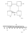
- the column 1 can be divided into individual rings which can be removed individually.
- the height of the column 1 can be adjusted depending on the height of the device placed on the plate 8 so that the screen is always at the height suitable for the user.
- This design of the column gives a very simple and inexpensive height adjustment of the plate 8 and of the entire device carrier.
- This type of height adjustment of the device plate 8 can also be implemented in devices in which no support arm 10 with support part 24 is provided.
- the column can have a hollow core which consists of tubes which can be telescoped into one another.
- the tubes are surrounded by the spacer rings, which can be removed or added if necessary.
- the individual rings can, for example, consist of semicircular ring segments which, after being inserted into the column 1, are joined to form a closed ring and are thus fastened.
- u-shaped spacers can also be used, which are pushed onto the core of the columns 1 and fastened in this position.
- a plate 64 which is triangular in the example, is arranged, and a nut 63 is screwed onto the bolt 60, with the interposition of a plate spring 61, which holds the slide 106 captively on the support part 104 and, at the same time, rotatably fastens a swivel part 66 to the slide 106 , to which a rod 68 is fastened, by means of which it can be rotated.
- the carriage 106 has two reinforcement zones 70, only one of which is visible in FIG. 4.
- the reinforcement zones 70 have bearing bores 71 which pivotally mount a swivel head 72 to which the plate 108 is fastened about a horizontal axis.
- the plate 64 Because of its angular shape and because of the limited width of the interior of the support part 104, the plate 64 forms a stop for perpendicular to the plane of the drawing in FIG. 4 the pivoting movement of the slide around the vertical axis.
- the swivel head 72 can thus be displaced in the longitudinal direction of the elongated hole 62, can be rotated to a limited extent about a variable vertical axis and, moreover, can be pivoted about a horizontal axis.
- the carriage 106 has a horizontally extending slot 92 and the pivot head 72 has an obliquely to the horizontal plane slot 93 through which the rod 68, which is slightly thinner than the width of the slots, passes. If the rod 68 is moved laterally in the slots 92, 93, the pivot head 72 is thereby pivoted in the bearing bores 71. The rod 68 can be pivoted about 80 ° in the horizontal plane. This movement corresponds to a movement of the swivel head 72 about a horizontal axis (bearing bores 71) of +/- 10 ° with respect to the horizontal plane.
- the friction between the carriage 106 and the support member 104 is selected so that the above-mentioned movement of the rod 68 does not normally affect the position of the swivel head with respect to its vertical swivel axis.
- the width of the elongated hole 62 is slightly larger than the thickness of the bolt 60.
- the rod 68 together with the slots 92 and 93, forms a drive device for the carrier, which uses at least one curve and a form-fitting coupling between an actuating device, namely the rod 68 in the exemplary embodiment, and the carrier.
- the entire device carrier can be attached to a table top by means of a clamping device 94.
- the column 101 is formed by a section 74 connected to the support part 104 and by an annularly detachably fastened at its lower end Section 76 formed. If necessary, further annular sections 76 can be provided to suitably adjust the length of the column 101 or the section 76 shown can be removed.
- the part 114 is connected to the further arm 118 by a link 80.
- the distance between the joints 112 and 82 on the one hand and 116 and 84 on the other hand is the same, and the distance between the joints 82 and 84 is the same as the distance between the joints 112 and 116.
- At the joint 116 there is also one end as a tension spring working gas spring 90 pivotally attached, the other end of which is pivotally attached to the handlebar 80.
- the gas spring 90 cannot prevent the support part 124 from lowering when the support arm 10 is pulled out to the left in FIG. 4, but it does slow down the lowering.
- the gas spring brings about a weight relief when lifting the support part 124 by hand.
- the gas spring has a piston which is sealed in a cylinder and slides.
- a concept holder 200 designed as a flat wire bracket is arranged on the top of the support arm 10 and 110 and rests resiliently on the support arm. If the support arm is inclined, you can easily read a text template that is clamped with the concept holder.
- the entire device carrier can be made of metal, but is preferably mainly made of plastic.
- the Sliding guidance of the support arm in the support part can take place in a different way from the example.
- FIG. 5 shows an embodiment of the plate 108 fastened on the swivel head, the size of which can be changed in both directions.
- a perforated plate 208 is attached to the swivel head, which in a regular arrangement bears a large number of cutouts, through holes 210 in the example.
- four support plates 212 which on their underside have matching projections 214, are placed in the desired position in such a way that projections 214 engage in holes 210.
- the projections fit so precisely in the holes that further fastening is not necessary. Instead, it is also possible to make only one or two (or even more) bores on the support plates instead of the projections and to connect the support plates to the perforated plate in the desired position by screw connections.
- the device to be placed on the equipment carrier e.g. a cathode ray viewer, arranged on the support plate 8, 108 and the plates 208, 212.
- This support plate thus forms the carrier mentioned at the beginning.
- a device can also be attached directly to the swivel head 72 of FIG. 4; In such a case, this swivel head forms the support mentioned at the outset, which is rotatably mounted about a vertical axis.
Landscapes
- Engineering & Computer Science (AREA)
- General Engineering & Computer Science (AREA)
- Mechanical Engineering (AREA)
- Input From Keyboards Or The Like (AREA)
- Casings For Electric Apparatus (AREA)
- Devices For Indicating Variable Information By Combining Individual Elements (AREA)
Applications Claiming Priority (2)
| Application Number | Priority Date | Filing Date | Title |
|---|---|---|---|
| DE8703224U | 1987-03-03 | ||
| DE8703224U DE8703224U1 (de) | 1987-03-03 | 1987-03-03 | Geräteträger |
Publications (2)
| Publication Number | Publication Date |
|---|---|
| EP0281093A2 true EP0281093A2 (fr) | 1988-09-07 |
| EP0281093A3 EP0281093A3 (fr) | 1989-06-14 |
Family
ID=6805423
Family Applications (1)
| Application Number | Title | Priority Date | Filing Date |
|---|---|---|---|
| EP88103149A Withdrawn EP0281093A3 (fr) | 1987-03-03 | 1988-03-02 | Support d'appareil |
Country Status (2)
| Country | Link |
|---|---|
| EP (1) | EP0281093A3 (fr) |
| DE (1) | DE8703224U1 (fr) |
Families Citing this family (4)
| Publication number | Priority date | Publication date | Assignee | Title |
|---|---|---|---|---|
| DE8703224U1 (de) * | 1987-03-03 | 1987-06-19 | Hebbel, Dierk, 7151 Allmersbach | Geräteträger |
| DE3820749C1 (en) * | 1988-06-18 | 1989-09-21 | Guenther 2300 Kiel De Krueger | Equipment support, in particular for the display unit and the keyboard of a data processing system |
| DE3933023A1 (de) * | 1989-10-01 | 1991-04-11 | Horst Haseke | Schwenkarm-geraetetraeger fuer edv- und buerogeraete |
| DE4214341A1 (de) * | 1992-05-09 | 1993-11-11 | Ivan Mallinowski | Computergehäuse mit Monitorstandfläche, welche arbeitsspezifisch verstellt werden kann |
Family Cites Families (6)
| Publication number | Priority date | Publication date | Assignee | Title |
|---|---|---|---|---|
| DE3379750D1 (en) * | 1982-06-07 | 1989-06-01 | Haworth Inc | Adjustable support for crt keyboard |
| GB8404507D0 (en) * | 1984-02-21 | 1984-03-28 | Spratling R J | Support unit |
| US4644875A (en) * | 1985-03-22 | 1987-02-24 | Weber-Knapp Company | Adjustable keyboard supporting mechanism |
| DE8512337U1 (de) * | 1985-04-23 | 1985-06-27 | Haseke GmbH & Co KG, 4952 Porta Westfalica | Geräteträger, insbesondere Monitorträger, mit einer neigbaren Geräteaufstellplatte |
| DE3614718C1 (de) * | 1986-04-30 | 1987-07-16 | Guenther Krueger | Vorrichtung zum Aufnehmen eines Datensichtgeraetes und einer mit diesem verbundenen Tastatur |
| DE8703224U1 (de) * | 1987-03-03 | 1987-06-19 | Hebbel, Dierk, 7151 Allmersbach | Geräteträger |
-
1987
- 1987-03-03 DE DE8703224U patent/DE8703224U1/de not_active Expired
-
1988
- 1988-03-02 EP EP88103149A patent/EP0281093A3/fr not_active Withdrawn
Also Published As
| Publication number | Publication date |
|---|---|
| EP0281093A3 (fr) | 1989-06-14 |
| DE8703224U1 (de) | 1987-06-19 |
Similar Documents
| Publication | Publication Date | Title |
|---|---|---|
| DE3036852C2 (de) | Vorrichtung zum Aufstellen eines Datensichtgerätes auf einer Arbeitsfläche | |
| DE2847135C3 (de) | Ständer für eine ein kastenförmiges Gehäuse aufweisende Informationsdarstellungseinheit | |
| EP0670405A1 (fr) | Dispositif de suspension de porte de vitrine pour la présentation d'articles | |
| DE8805679U1 (de) | Tisch mit höhenverstellbarer und kippbarer Tischplatte | |
| DE3613005A1 (de) | Metalltisch | |
| EP0172320A1 (fr) | Bras orientable | |
| EP0372398A2 (fr) | Pupitre de lecture | |
| DE202018102954U1 (de) | Klimmzugstange | |
| EP0281093A2 (fr) | Support d'appareil | |
| WO1984003573A1 (fr) | Installation de support pour un clavier relie a un appareil de bureautique | |
| EP1944112B1 (fr) | Scie circulaire à table | |
| DE29713556U1 (de) | Bildschirm-Schwenkarm | |
| EP0482416A1 (fr) | Meuble, en particulier une table | |
| DE69032072T2 (de) | Nach wahl einstellbarer untersatz für tastatur | |
| DE3301467A1 (de) | Traegeranordnung fuer ein datensichtgeraet | |
| DE10260587A1 (de) | Flipchart | |
| EP0045925A1 (fr) | Meuble d'assise, particulièrement chaise de bureau tournante | |
| DE3826534A1 (de) | Lesegeraet fuer buecher | |
| DE29820232U1 (de) | Vorrichtung zum Auflegen von Angelruten | |
| EP0826498B1 (fr) | Imprimeuse en tampographie | |
| EP2860409B1 (fr) | Dispositif de fixation d'objets sur des plateaux de table | |
| DE202019105069U1 (de) | Tisch mit einer Tischplatte und einem Tischplattenergänzungsteil | |
| DE2402420A1 (de) | Selbstarretierende stuetzvorrichtung | |
| DE19511176A1 (de) | Vorrichtung zur Verstellung der Höhe und/oder Neigung der Tischplatte eines Tisches | |
| DE2843438A1 (de) | Vorrichtung zum auftragen von klebemitteln auf waermedaemmplatten |
Legal Events
| Date | Code | Title | Description |
|---|---|---|---|
| PUAI | Public reference made under article 153(3) epc to a published international application that has entered the european phase |
Free format text: ORIGINAL CODE: 0009012 |
|
| AK | Designated contracting states |
Kind code of ref document: A2 Designated state(s): CH ES FR GB LI NL SE |
|
| PUAL | Search report despatched |
Free format text: ORIGINAL CODE: 0009013 |
|
| AK | Designated contracting states |
Kind code of ref document: A3 Designated state(s): CH ES FR GB LI NL SE |
|
| STAA | Information on the status of an ep patent application or granted ep patent |
Free format text: STATUS: THE APPLICATION IS DEEMED TO BE WITHDRAWN |
|
| 18D | Application deemed to be withdrawn |
Effective date: 19891215 |