EP0281114B1 - Farbbildröhre - Google Patents
Farbbildröhre Download PDFInfo
- Publication number
- EP0281114B1 EP0281114B1 EP88103201A EP88103201A EP0281114B1 EP 0281114 B1 EP0281114 B1 EP 0281114B1 EP 88103201 A EP88103201 A EP 88103201A EP 88103201 A EP88103201 A EP 88103201A EP 0281114 B1 EP0281114 B1 EP 0281114B1
- Authority
- EP
- European Patent Office
- Prior art keywords
- spring members
- frame
- shadow mask
- spring
- tube according
- Prior art date
- Legal status (The legal status is an assumption and is not a legal conclusion. Google has not performed a legal analysis and makes no representation as to the accuracy of the status listed.)
- Expired - Lifetime
Links
- OAICVXFJPJFONN-UHFFFAOYSA-N Phosphorus Chemical compound [P] OAICVXFJPJFONN-UHFFFAOYSA-N 0.000 claims description 21
- 230000002093 peripheral effect Effects 0.000 claims description 7
- 238000005452 bending Methods 0.000 claims description 4
- 238000003466 welding Methods 0.000 claims description 2
- 238000010894 electron beam technology Methods 0.000 description 9
- XEEYBQQBJWHFJM-UHFFFAOYSA-N Iron Chemical compound [Fe] XEEYBQQBJWHFJM-UHFFFAOYSA-N 0.000 description 4
- 230000003247 decreasing effect Effects 0.000 description 3
- 239000000463 material Substances 0.000 description 3
- 230000005855 radiation Effects 0.000 description 3
- 229910045601 alloy Inorganic materials 0.000 description 2
- 239000000956 alloy Substances 0.000 description 2
- 239000010960 cold rolled steel Substances 0.000 description 2
- 239000011521 glass Substances 0.000 description 2
- 229910052742 iron Inorganic materials 0.000 description 2
- 238000004519 manufacturing process Methods 0.000 description 2
- 239000010935 stainless steel Substances 0.000 description 2
- 229910001220 stainless steel Inorganic materials 0.000 description 2
- 229910019589 Cr—Fe Inorganic materials 0.000 description 1
- 229910017060 Fe Cr Inorganic materials 0.000 description 1
- 229910002544 Fe-Cr Inorganic materials 0.000 description 1
- 238000013459 approach Methods 0.000 description 1
- UPHIPHFJVNKLMR-UHFFFAOYSA-N chromium iron Chemical compound [Cr].[Fe] UPHIPHFJVNKLMR-UHFFFAOYSA-N 0.000 description 1
- 238000005336 cracking Methods 0.000 description 1
- 230000006866 deterioration Effects 0.000 description 1
- 230000005489 elastic deformation Effects 0.000 description 1
- 238000010438 heat treatment Methods 0.000 description 1
- 238000000034 method Methods 0.000 description 1
- 238000003825 pressing Methods 0.000 description 1
- 230000035939 shock Effects 0.000 description 1
Images


Classifications
-
- H—ELECTRICITY
- H01—ELECTRIC ELEMENTS
- H01J—ELECTRIC DISCHARGE TUBES OR DISCHARGE LAMPS
- H01J29/00—Details of cathode-ray tubes or of electron-beam tubes of the types covered by group H01J31/00
- H01J29/02—Electrodes; Screens; Mounting, supporting, spacing or insulating thereof
- H01J29/06—Screens for shielding; Masks interposed in the electron stream
- H01J29/07—Shadow masks for colour television tubes
- H01J29/073—Mounting arrangements associated with shadow masks
-
- H—ELECTRICITY
- H01—ELECTRIC ELEMENTS
- H01J—ELECTRIC DISCHARGE TUBES OR DISCHARGE LAMPS
- H01J29/00—Details of cathode-ray tubes or of electron-beam tubes of the types covered by group H01J31/00
- H01J29/02—Electrodes; Screens; Mounting, supporting, spacing or insulating thereof
Definitions
- the present invention relates to a color picture tube and, more particularly, to a supporting assembly for connecting a shadow mask to the front panel of a color picture tube.
- a color picture tube comprises three electron guns, a front panel, a phosphor screen formed on the inner surface of the front panel, a rigid mask frame, and a shadow mask supported by the rigid mask frame and facing the phosphor screen.
- the shadow mask has a plurality of apertures through which electron beams emitted from the guns pass before striking the phosphor screen.
- the rigid mask frame surrounds the peripheral edge of the shadow mask, thus maintaining the shape of the shadow mask.
- the color picture tube further comprises a supporting assembly which supports the mask frame. The mask frame can be detached from the supporting assembly, and thus too can the shadow mask.
- a bimetal is incorporated in the supporting assembly. This bimetal functions to move the shadow mask as the mask thermally expands, so that the electron beams passing through the apertures of the mask can land on the desired portions of the phosphor screen.
- the bimetal cannot move the shadow mask sufficiently quickly after the mask has begun to thermally expanded, and thus mislanding of the beam occurs.
- incorporated of the bimetal which is relatively heavy, renders the picture tube undesirably heavy.
- Japanese Patent Publication No. 46-4104 discloses a rectangular mask frame having four leaf springs which project one from each of the four corners and are connected to the four corners of a shadow mask, thereby supporting the shadow mask. As a result, when the shadow mask thermally expands, deformation of the mask frame is less than that of the mask frame surrounding the shadow mask.
- the use of this mask frame results in the following advantages:
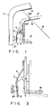
- Fig. 1 shows a conventional assembly for supporting the shadow mask of a color picture tube similar to the supporting assembly shown in EP-A-207 724, which is a combination made up of stud pin 24 which projects from an inner peripheral wall of panel 11, and leaf spring 2 having a hole through which stud pin 24 extends. Stud pin 24 is tapered at an angle of about 12°.
- Leaf spring 2 is composed of three portions, i.e., fixed portion 3 welded to frame 18 and located near phosphor screen 14; elastically deformable portion 4; and engaging portion 5 supported by stud pin 24, on its rear side, and located remote from screen 14.
- Leaf spring 2 has a substantially V-shaped longitudinal section.
- the angle (0) defined by movable portion 4 and frame 18 should be 45° in the case of a picture tube having a beam deflection angle of 90°, and 35° in the case of a picture tube having a beam deflection angle of 110°, in order to compensate only for the mislanding of electron beams 15 which has resulted from the thermal expansion of shadow mask 17.
- Spring 2 is attached to frame 18 to have an angle ⁇ larger than the above-mentioned value, e.g., to be about 70 degrees or more in a picture tube having a beam deflection angle of 90 degrees, so as to increase the shift amount of frame 18 by spring 2.
- angle ⁇ is increased, the spring constant of spring 2 becomes too large, and it is difficult to detach shadow mask assembly from panel 11, resulting in a variety of problems in respect of manufacture and use.
- an attachment/detachment of a shadow mask to/from a panel must be repetitively performed.
- leaf springs When leaf springs are used, the attachment/detachment cannot be manually performed and must be performed by a special-purpose apparatus installed for each process.
- a large force acts on a supporting assembly, a mask frame, and a shadow mask during attachment/detachment of the shadow mask, and may deform these parts.
- the thermal expansion coefficient of a material constituting a stud pin must be substantially the same as that constituting the panel, in order to prevent the stud pin from cracking at the projecting portion.
- an Fe-Cr alloy (Cr: 18 wt.%) is normally employed as a material of the stud pin. This material is soft, i.e., has a Vickers hardness (Hv) of about 150.
- Leaf spring 2 is normally formed of hard stainless steel having an Hv of 380 to 500. When a rigid spring is used, the stud pin is recessed at a contacting portion, and mounting precision of the shadow mask is degraded.
- the mounting angle ⁇ cannot be increased, and purity drift in a continuous operation for a long period of time cannot be satisfactorily compensated. Therefore, a deterioration of color purity near a peripheral region of the screen occurs.
- a modified embodiment shown in US 3 492 522 has a V-shaped spring member.
- the V-shaped spring becomes curved and approaches the screen.
- a color picture tube in which the supporting assembly detachably mounting the shadow mask on the front panel adjacent to the phosphor screen comprises at least three glass cams, that means stud pins asymmetrically projecting from the front panel along the periphery of an annular frame supporting the shadow mask.
- the stud pins are attached to side portions of the front panel, respectively.
- deformable elements being an equivalent of spring members comprise parallel strips, are provided. When the frame is thermally expanded, the parallel strips move due to their elastic deformation.
- the present invention has as its object to provide a color picture tube which can satisfactorily compensate for purity drift occuring after a long use of the picture tube, and hence can improve image quality.
- a color picture tube comprising: A color picture tube, comprising: a CRT envelope having a front panel, the front panel being composed of a substantially rectangular faceplate surrounded by a skirt, and a central line axis substantially perpendicular to the faceplate; a phosphor screen formed on the inner surface of the face plate; a shadow mask assembly including
- JP-A-53144252 a shadow mask supporting assembly in which an attachment panel is fixed to a front panel, and a projecting part of a V-shaped elastic supporter bar is fitted to the hole of the panel.
- the projecting part of the bar is immovable within the hole, because the supporter bar is pushed against the attachment panel by a spring. It follows that, in this supporting assembly it is impossible to define an angle ⁇ as in the present invention.
- angle ⁇ preferably falls within the range of 60 to 80 degrees, and most preferably, 70 degrees.
- Angle ⁇ preferably falls within the range of 45 to 65 degrees, and most preferably, 55 degrees.
- angle a preferably falls within the range of 50 to 70 degrees, and most preferably, 60 degrees.
- Angle ⁇ preferably falls within the range of 35 to 55 degrees, and most preferably, 45 degrees.
- each spring member preferably falls within the range of 0.3 to 0.8 mm.
- the thickness of the mask frame preferably falls within the range of 0.5 to 2.0 mm.
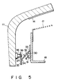
- a vacuum envelope of color picture tube 10 is constituted by substantially rectangular panel 11, fan-shaped funnel 12, and neck 13.
- Tri-color phosphor screen 14 consisting of stripe phosphor layers which emit red, green, and blue light, respectively, is deposited on the inner surface of panel 11.
- So-called inline type electron guns 16 which are aligned along the horizontal axis of panel 11 and emit three electron beams 15 corresponding to red, green, and blue, are disposed in neck 13.
- Shadow mask 17 in which a large number of slot apertures are formed is disposed to face phosphor screen 14.
- Substantially rectangular mask frame 18 is provided at the peripheral edge of shadow mask 17 so as to keep shadow mask 17 in position.
- Spring members 30 such as leaf springs, each having a through hole, are attached to the four corners of frame 18.
- the through holes of spring members 30 respectively receive stud pins 24 projecting from the four corners of the inner periphery of the panel 11 (Fig. 4). More specifically, when four spring members 30 are engaged with four stud pins 24, shadow mask 17 is supported inside panel 11 through frame 18.
- Three inline electron beams 15 are deflected by deflection device 22 outside funnel 12, scan a rectangular region corresponding to panel 11, and land on stripe phosphor screen 14 while being color-separated through slot apertures of shadow mask 17, thereby reproducing a color image.
- magnetic shield 21 is engaged inside funnel 12 through frame 18.
- Shadow mask 17 is formed of a 0.2-mm thick cold-rolled steel plate containing iron as a major component, and its peripheral edge is fixed to mask frame 18.
- Mask frame 18 is formed of a 0.5-mm thick cold-rolled steel plate containing iron as a major component, and its axial section is L-shaped.
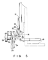
- Each spring member 30 has a substantially N-shaped section.
- Each spring member 30 is formed of a 0.4-mm thick precipitation-hardened stainless steel plate having good spring characteristics, e.g., an SUS 631 thin plate.
- each spring member 30 is fixed by welding to the outer peripheral surface of frame 18.
- Movable portion 32 is formed by bending both ends of a thin plate through 55 degrees in opposite directions. One end of portion 32 is welded to an end portion (near phosphor screen 14) of fixed portion 31, and another end thereof is welded to an end portion (farther from phosphor screen 14) of engaging portion 35. More specifically, spring member 30 is attached so that angle ⁇ defined by frame 18 and portion 32 is about 55 degrees. Hole 36 is formed at the center in the widthwise direction of engaging portion 35. When the shadow mask is attached to the panel, the distal end portion of each stud pin 24 is fitted in corresponding hole 36. In this case, angle ⁇ defined by line 38 connecting the distal end central portion of stud pin 24 and bent position 33 of portion 32, and the axis of body is about 70 degrees.
- Stud pins 24 project from the inner periphery of glass panel 11.
- Each stud pin 24 has a frustoconical distal end portion, and is formed of a Cr-Fe alloy (Cr: 18 wt.%).
- collar 37 is formed around hole 36 of each engaging portion 35 substantially along the tapered surface of corresponding stud pin 24, so that stud pin 24 and engaging portion 35 are smoothly slid each other.
- Electron beam radiation conditions in this case are: an anode voltage of 25 kV, an anode current of 1,400 ⁇ A, and a radiation time of 90 minutes.
- the shadow mask When electron beams are continuously radiated through the shadow mask, the shadow mask is thermally expanded in a short period of time. In a minute, mask frame 18 is heated, and the frame diameter is increased. When the diameter of frame 18 is increased by radiation for a long period of time, portion 32 of each spring member 30 is pushed toward corresponding stud pin 24, and is deformed to decrease initial angle ⁇ to angle ⁇ 1. Thus, frame 18 is shifted toward the phosphor screen by a distance of (cos ⁇ 1 - cos ⁇ ) ⁇ L, and purity drift can be compensated for.
- Reference symbol L indicates a length between bent positions 33 to 34 of portion 32. In this case, spring member 30 is swung about hole 36 of engaging portion 35, and engaging portion 35 is inclined to compensate for the purity drift.
- angle ⁇ When angle ⁇ is increased, angle ⁇ can be decreased while maintaining a predetermined shift amount (correction amount). Therefore, a leaf spring having a small spring constant can be employed, and spring fatigue can be effectively prevented. For this reason, a shadow mask can be easily attached/detached to/from the panel without damaging and deforming the parts.
- the thickness of the mask frame can be decreased, and the picture tube can be rendered lightweight.
- the mislanding can be substantially eliminated. For this reason, color purity in the screen corner regions is not deteriorated in a continuous operation for a long period of time, and a clear image can be obtained.
- each spring member is combinated by two plates. More specifically, in spring member 40 of the second embodiment, the fixed portion of the first embodiment is omitted, and the bent end portion of the movable portion is directly welded to frame 18.
- both ends of the elastically deformable portion are bent in an identical direction so that they are parallel to each other. More specifically, one end portion is bent at an angle of about 125 degrees, and the bent end portion is directly welded to frame 18.
- each spring member is constituted by a single plate. More specifically, in spring member 60, the both ends of the elastically deformable portion are bent at an angle of about 125 degrees in opposite directions, and one bent end is directly welded to frame 18. A hole is formed in the other bent end portion to be engaged with the stud pin 24.
- the number of parts constituting the spring member can be decreased, thus improving productivity, and reducing cost.
Landscapes
- Electrodes For Cathode-Ray Tubes (AREA)
Claims (11)
- Farbbildröhre, umfassend:
einen Kathodenstrahlröhren-Kolben mit einer Frontscheibe (11), welche Frontscheibe (11) aus einem im wesentlichen rechteckigen, von einem Kragen umgebenen Schirmträger gebildet ist, und (mit) einer im wesentlichen senkrecht zum Schirmträger verlaufenden Mittellinienachse,
einen an der Innenfläche des Schirmträgers geformten Leuchtstoffschirm (14),
eine Lochmaskenanordnung mit(a) einer Lochmaske (17),(b) einem die Lochmaske umgebenden Rahmen (18) und(c) einer Halterungsanordnung zur abnehmbaren Halterung der Lochmaske in Gegenüberstellung zum Leuchtstoffschirm (14), so daß die Lochmaske dem Leuchtstoffschirm zugewandt ist,wobei die Halterungsanordnung aufweist:
senkrecht von der Innenwand des Kragens abstehende Stehbolzen (24) und
Federelemente (30, 40, 50, 60) mit jeweils zwei Enden, von denen das eine Ende am Rahmen (18) festgelegt ist und das andere Ende trennbar mit einem betreffenden der Stehbolzen (24) in Eingriff steht, wobei jedes der Federelemente (30, 40, 50, 60) einen einzigen geraden, streifenförmigen, elastisch verformbaren, zwischen den beiden Enden gelegenen Abschnitt (32) aufweist,
wobei die Stehbolzen (24) von den vier Ecken der Frontscheibe (11) abstehen,
wobei die Federelemente (30, 40, 50, 60) einen Einrastabschnitt (35) für Eingriff mit dem Stehbolzen (24) aufweisen, so daß bei einer Verschiebung der Federelemente (30, 40, 50, 60) als Folge einer Wärmeausdehnung des Rahmens ein Ende des Einrastabschnitts (35), das weiter als der Stehbolzen (24) vom Schirm (14) entfernt ist, vom Kragen des Kathodenstrahlröhren-Kolbens hinweg verschoben wird,
dadurch gekennzeichnet, daß
der einzige gerade, streifenförmige, elastisch verformbare Abschnitt (32) der Federelemente (30, 40, 50, 60) und die parallel zur Mittellinienachse liegende Ebene des Rahmens (18), an welcher die Federelemente (30, 40, 50, 60) montiert sind, einen Winkel β festlegen, und eine Linie (38), welche den Endabschnitt des einzigen geraden, streifenförmigen, elastisch verformbaren Abschnitts (32) an der Seite des Rahmens (18) mit dem Stehbolzen (24) verbindet, und die Ebene des Rahmens (18), an welcher das Federelement (30, 40, 50, 60) montiert ist, einen Winkel α festlegen, wobei
der Endabschnitt des einzigen geraden, streifenförmigen, elastisch verformbaren Abschnitts (32) an der Seite des Einrastabschnitts (35) weiter als der Stehbolzen (24) vom Schirm (14) entfernt ist, und wobei gilt

- Röhre nach Anspruch 1,
dadurch gekennzeichnet, daß jedes der Federelemente (30, 40, 50) einen im wesentlichen N-förmigen Längsschnitt aufweist. - Röhre nach Anspruch 1,
wobei jedes der Federelemente (40) ferner einen eingerasteten Abschnitt aufweist, der in trennbarem Eingriff mit dem betreffenden Ende eines der Stehbolzen (24) steht, und wobei der streifenförmige, elastisch verformbare Abschnitt (32) und der eingerastete Abschnitt unter Bildung einer im wesentlichen V-förmigen Feder miteinander verbunden sind. - Röhre nach Anspruch 1, dadurch gekennzeichnet, daß jedes der Federelemente (30, 40, 50) eine aus einer Anzahl dünner Platten oder Bleche gebildete Blattfeder umfaßt.
- Röhre nach Anspruch 1, dadurch gekennzeichnet, daß jedes der Federelemente (30, 40, 50) eine Blattfeder umfaßt, die durch Biegen beider Enden einer (eines) dünnen Platte oder Blechs in entgegengesetzten Richtungen, so daß beide Endabschnitte parallel zueinander liegen, geformt ist.
- Röhre nach Anspruch 1, dadurch gekennzeichnet, daß jedes der Federelemente (50) eine Blattfeder umfaßt, die durch Biegen beider Enden einer (eines) dünnen Platte oder Blechs in einer identischen (jeweils gleichen) Richtung, so daß beide Endabschnitte parallel zueinander liegen, geformt ist.
- Röhre nach Anspruch 1, dadurch gekennzeichnet, daß jedes der Federelemente (60) eine durch Biegen einer (eines) einzigen dünnen Platte oder Blechs geformte Blattfeder umfaßt.
- Röhre nach Anspruch 1, dadurch gekennzeichnet, daß in einem freien Endabschnitt eines jeden Federelements (30, 40, 50, 60) eine durchgehende Bohrung (36) geformt ist, in welche ein betreffender der Stehbolzen (24) eingreift.
- Röhre nach Anspruch 8, dadurch gekennzeichnet, daß jeder Stehbolzen (24) eine kegelstumpfförmige Gestalt aufweist.
- Röhre nach Anspruch 8, dadurch gekennzeichnet, daß ein Umfangsrandabschnitt der durchgehenden Bohrung (36) unter Bildung eines Kragens (37) gebogen ist.
- Röhre nach Anspruch 1, dadurch gekennzeichnet, daß ein Ende jedes der Federelemente (30, 40, 50, 60) durch Schweißen am Rahmen (18) befestigt ist.
Applications Claiming Priority (2)
| Application Number | Priority Date | Filing Date | Title |
|---|---|---|---|
| JP62050199A JP2592826B2 (ja) | 1987-03-06 | 1987-03-06 | カラー受像管 |
| JP50199/87 | 1987-03-06 |
Publications (2)
| Publication Number | Publication Date |
|---|---|
| EP0281114A1 EP0281114A1 (de) | 1988-09-07 |
| EP0281114B1 true EP0281114B1 (de) | 1993-11-10 |
Family
ID=12852463
Family Applications (1)
| Application Number | Title | Priority Date | Filing Date |
|---|---|---|---|
| EP88103201A Expired - Lifetime EP0281114B1 (de) | 1987-03-06 | 1988-03-02 | Farbbildröhre |
Country Status (6)
| Country | Link |
|---|---|
| US (1) | US4886997A (de) |
| EP (1) | EP0281114B1 (de) |
| JP (1) | JP2592826B2 (de) |
| KR (1) | KR900009075B1 (de) |
| CN (1) | CN1010353B (de) |
| DE (1) | DE3885478T2 (de) |
Families Citing this family (9)
| Publication number | Priority date | Publication date | Assignee | Title |
|---|---|---|---|---|
| US4950941A (en) * | 1989-07-21 | 1990-08-21 | Rca Licensing Corporation | Color picture tube having improved shadow mask-frame assembly support |
| US5021707A (en) * | 1989-11-17 | 1991-06-04 | Rca Licensing Corporation | Color picture tube having shadow mask with improved support |
| US5128585A (en) * | 1990-03-16 | 1992-07-07 | Thomson Consumer Electronics, Inc. | Color picture tube having improved corner support for a shadow mask-frame assembly |
| KR950005393Y1 (ko) * | 1991-04-01 | 1995-07-08 | 주식회사 Lg전자 | 칼라수상관의 새도우 마스크 탄성지지부재 |
| JP3516462B2 (ja) * | 1993-05-20 | 2004-04-05 | ソニー株式会社 | 陰極線管の製造方法 |
| KR960012414B1 (ko) * | 1993-07-05 | 1996-09-20 | 엘지전자주식회사 | 칼라수상관의 섀도우마스크 지지용 탄성부재 |
| JP3259552B2 (ja) * | 1994-12-12 | 2002-02-25 | 三菱電機株式会社 | カラーブラウン管用色選別電極構体 |
| US6249081B1 (en) * | 1999-04-12 | 2001-06-19 | Osram Sylvania Inc. | Low chromium ferritic stainless steel studs for cathode ray tubes |
| KR100669044B1 (ko) * | 2004-10-15 | 2007-01-16 | 엘지.필립스 디스플레이 주식회사 | 음극선관용 프레임 |
Citations (2)
| Publication number | Priority date | Publication date | Assignee | Title |
|---|---|---|---|---|
| JPS53144252A (en) * | 1977-05-20 | 1978-12-15 | Matsushita Electronics Corp | Color picture tube |
| EP0195357A2 (de) * | 1985-03-11 | 1986-09-24 | Kabushiki Kaisha Toshiba | Farbbildröhre |
Family Cites Families (8)
| Publication number | Priority date | Publication date | Assignee | Title |
|---|---|---|---|---|
| NL6616317A (de) * | 1966-11-19 | 1968-05-20 | ||
| NL151552B (nl) * | 1967-02-02 | 1976-11-15 | Philips Nv | Kleurentelevisieweergeefbuis. |
| US3492522A (en) * | 1967-08-15 | 1970-01-27 | Zenith Radio Corp | Shadow mask supported by v-shaped springs having apices directed toward gun |
| JPS54159166A (en) * | 1978-06-07 | 1979-12-15 | Hitachi Ltd | Supporter for shadow mask |
| JPS54179056U (de) * | 1978-06-07 | 1979-12-18 | ||
| JPS55109344A (en) * | 1979-02-16 | 1980-08-22 | Toshiba Corp | Shadow mask supporting body |
| JPS61245445A (ja) * | 1985-04-23 | 1986-10-31 | Toshiba Corp | シヤドウマスク形カラ−受像管 |
| JPH0815055B2 (ja) * | 1985-06-27 | 1996-02-14 | 株式会社東芝 | カラ−受像管 |
-
1987
- 1987-03-06 JP JP62050199A patent/JP2592826B2/ja not_active Expired - Lifetime
-
1988
- 1988-03-02 DE DE88103201T patent/DE3885478T2/de not_active Expired - Lifetime
- 1988-03-02 US US07/163,100 patent/US4886997A/en not_active Expired - Lifetime
- 1988-03-02 EP EP88103201A patent/EP0281114B1/de not_active Expired - Lifetime
- 1988-03-05 KR KR1019880002358A patent/KR900009075B1/ko not_active Expired
- 1988-03-05 CN CN88101194A patent/CN1010353B/zh not_active Expired
Patent Citations (3)
| Publication number | Priority date | Publication date | Assignee | Title |
|---|---|---|---|---|
| JPS53144252A (en) * | 1977-05-20 | 1978-12-15 | Matsushita Electronics Corp | Color picture tube |
| JPS58144B2 (ja) * | 1977-05-20 | 1983-01-05 | 松下電子工業株式会社 | カラ−受像管 |
| EP0195357A2 (de) * | 1985-03-11 | 1986-09-24 | Kabushiki Kaisha Toshiba | Farbbildröhre |
Non-Patent Citations (1)
| Title |
|---|
| PATENT ABSTRACTS OF JAPAN vol. 003, no. 017 (E - 90)<26> 14 February 1979 (1979-02-14) * |
Also Published As
| Publication number | Publication date |
|---|---|
| CN1010353B (zh) | 1990-11-07 |
| CN88101194A (zh) | 1988-09-14 |
| KR900009075B1 (ko) | 1990-12-20 |
| EP0281114A1 (de) | 1988-09-07 |
| US4886997A (en) | 1989-12-12 |
| JP2592826B2 (ja) | 1997-03-19 |
| DE3885478T2 (de) | 1994-03-24 |
| KR880011865A (ko) | 1988-10-31 |
| JPS63218126A (ja) | 1988-09-12 |
| DE3885478D1 (de) | 1993-12-16 |
Similar Documents
| Publication | Publication Date | Title |
|---|---|---|
| EP0304922B1 (de) | Farbbildröhre | |
| EP0268485B1 (de) | Farbbildröhre | |
| US4437036A (en) | Cathode-ray tube having a temperature compensated mask-frame assembly | |
| EP0281114B1 (de) | Farbbildröhre | |
| US4300071A (en) | Four-corner shadow mask suspension system for television cathode ray tubes | |
| EP0655762B1 (de) | Farbkathodenstrahlröhre | |
| US5982085A (en) | Color cathode ray tube with improved shadow mask mounting system | |
| US4572983A (en) | Color picture tube having an improved support structure for a color selection electrode | |
| US4613785A (en) | Color picture tube having an improved simplified support structure for a color selection electrode | |
| EP0578251B1 (de) | Farbbildkathodenstrahlröhre | |
| EP0187026B1 (de) | Farbbildröhre | |
| US4659958A (en) | Support means for use with a low expansion color-selection electrode | |
| EP0878821B1 (de) | Kathodenstrahlröhre mit Befestigungselementen für den Schattenmaskenrahmen | |
| US6707243B2 (en) | Color cathode ray tube having an improved shadow mask supporting structure | |
| EP0882306B1 (de) | Farbkathodenstrahlröhre und deren herstellungsverfahren | |
| EP1306875B1 (de) | Spannmaske für Kathodenstrahlröhre | |
| US6211609B1 (en) | Corner spring for color cathode ray tube | |
| US6720721B2 (en) | Color cathode ray tube having an improved shadow mask supporting structure | |
| KR200262572Y1 (ko) | 칼라음극선관용 새도우마스크 | |
| US6144148A (en) | Thermal expansion for color CRT | |
| EP1001446A1 (de) | Farbkathodenstrahlröhre, elastisches stützelement und elastischer stutsmechanismus | |
| EP0677863B1 (de) | Farb Kathodenstrahlröhre | |
| KR100261453B1 (ko) | 음극선관용 마스크 프레임 | |
| KR20000066352A (ko) | 브라운관용 프레임의 구조 | |
| KR19990036690U (ko) | 칼라음극선관용 새도우마스크 |
Legal Events
| Date | Code | Title | Description |
|---|---|---|---|
| PUAI | Public reference made under article 153(3) epc to a published international application that has entered the european phase |
Free format text: ORIGINAL CODE: 0009012 |
|
| 17P | Request for examination filed |
Effective date: 19880330 |
|
| AK | Designated contracting states |
Kind code of ref document: A1 Designated state(s): DE FR GB |
|
| 17Q | First examination report despatched |
Effective date: 19891013 |
|
| GRAA | (expected) grant |
Free format text: ORIGINAL CODE: 0009210 |
|
| AK | Designated contracting states |
Kind code of ref document: B1 Designated state(s): DE FR GB |
|
| REF | Corresponds to: |
Ref document number: 3885478 Country of ref document: DE Date of ref document: 19931216 |
|
| ET | Fr: translation filed | ||
| PLBE | No opposition filed within time limit |
Free format text: ORIGINAL CODE: 0009261 |
|
| STAA | Information on the status of an ep patent application or granted ep patent |
Free format text: STATUS: NO OPPOSITION FILED WITHIN TIME LIMIT |
|
| 26N | No opposition filed | ||
| REG | Reference to a national code |
Ref country code: GB Ref legal event code: 746 Effective date: 19981008 |
|
| REG | Reference to a national code |
Ref country code: FR Ref legal event code: D6 |
|
| REG | Reference to a national code |
Ref country code: GB Ref legal event code: IF02 |
|
| PGFP | Annual fee paid to national office [announced via postgrant information from national office to epo] |
Ref country code: DE Payment date: 20070222 Year of fee payment: 20 |
|
| PGFP | Annual fee paid to national office [announced via postgrant information from national office to epo] |
Ref country code: GB Payment date: 20070228 Year of fee payment: 20 |
|
| REG | Reference to a national code |
Ref country code: GB Ref legal event code: PE20 |
|
| PGFP | Annual fee paid to national office [announced via postgrant information from national office to epo] |
Ref country code: FR Payment date: 20070308 Year of fee payment: 20 |
|
| PG25 | Lapsed in a contracting state [announced via postgrant information from national office to epo] |
Ref country code: GB Free format text: LAPSE BECAUSE OF EXPIRATION OF PROTECTION Effective date: 20080301 |