EP0281183A1 - Dispositif et procédé pour la manipulation et la commande du fil d'une machine de bobinage à cônes pendant les opérations de remplacement de bobine et de rattachement du fil - Google Patents
Dispositif et procédé pour la manipulation et la commande du fil d'une machine de bobinage à cônes pendant les opérations de remplacement de bobine et de rattachement du fil Download PDFInfo
- Publication number
- EP0281183A1 EP0281183A1 EP88200285A EP88200285A EP0281183A1 EP 0281183 A1 EP0281183 A1 EP 0281183A1 EP 88200285 A EP88200285 A EP 88200285A EP 88200285 A EP88200285 A EP 88200285A EP 0281183 A1 EP0281183 A1 EP 0281183A1
- Authority
- EP
- European Patent Office
- Prior art keywords
- thread
- handling
- nozzle
- control
- machine during
- Prior art date
- Legal status (The legal status is an assumption and is not a legal conclusion. Google has not performed a legal analysis and makes no representation as to the accuracy of the status listed.)
- Granted
Links
- 230000008859 change Effects 0.000 title claims abstract description 14
- 238000000034 method Methods 0.000 title claims abstract description 14
- 230000008569 process Effects 0.000 title claims abstract description 14
- 238000005520 cutting process Methods 0.000 claims abstract description 22
- 230000009471 action Effects 0.000 claims description 9
- 239000000428 dust Substances 0.000 claims description 4
- 244000144992 flock Species 0.000 claims description 3
- 230000015572 biosynthetic process Effects 0.000 claims description 2
- 230000007547 defect Effects 0.000 description 3
- 239000000203 mixture Substances 0.000 description 2
- 230000000694 effects Effects 0.000 description 1
- 239000000284 extract Substances 0.000 description 1
- 230000001360 synchronised effect Effects 0.000 description 1
- 238000004804 winding Methods 0.000 description 1
Images

Classifications
-
- B—PERFORMING OPERATIONS; TRANSPORTING
- B65—CONVEYING; PACKING; STORING; HANDLING THIN OR FILAMENTARY MATERIAL
- B65H—HANDLING THIN OR FILAMENTARY MATERIAL, e.g. SHEETS, WEBS, CABLES
- B65H54/00—Winding, coiling, or depositing filamentary material
- B65H54/02—Winding and traversing material on to reels, bobbins, tubes, or like package cores or formers
- B65H54/22—Automatic winding machines, i.e. machines with servicing units for automatically performing end-finding, interconnecting of successive lengths of material, controlling and fault-detecting of the running material and replacing or removing of full or empty cores
-
- B—PERFORMING OPERATIONS; TRANSPORTING
- B65—CONVEYING; PACKING; STORING; HANDLING THIN OR FILAMENTARY MATERIAL
- B65H—HANDLING THIN OR FILAMENTARY MATERIAL, e.g. SHEETS, WEBS, CABLES
- B65H54/00—Winding, coiling, or depositing filamentary material
- B65H54/70—Other constructional features of yarn-winding machines
- B65H54/702—Arrangements for confining or removing dust
-
- B—PERFORMING OPERATIONS; TRANSPORTING
- B65—CONVEYING; PACKING; STORING; HANDLING THIN OR FILAMENTARY MATERIAL
- B65H—HANDLING THIN OR FILAMENTARY MATERIAL, e.g. SHEETS, WEBS, CABLES
- B65H69/00—Methods of, or devices for, interconnecting successive lengths of material; Knot-tying devices ;Control of the correct working of the interconnecting device
-
- B—PERFORMING OPERATIONS; TRANSPORTING
- B65—CONVEYING; PACKING; STORING; HANDLING THIN OR FILAMENTARY MATERIAL
- B65H—HANDLING THIN OR FILAMENTARY MATERIAL, e.g. SHEETS, WEBS, CABLES
- B65H2301/00—Handling processes for sheets or webs
- B65H2301/50—Auxiliary process performed during handling process
- B65H2301/53—Auxiliary process performed during handling process for acting on performance of handling machine
- B65H2301/531—Cleaning parts of handling machine
-
- B—PERFORMING OPERATIONS; TRANSPORTING
- B65—CONVEYING; PACKING; STORING; HANDLING THIN OR FILAMENTARY MATERIAL
- B65H—HANDLING THIN OR FILAMENTARY MATERIAL, e.g. SHEETS, WEBS, CABLES
- B65H2701/00—Handled material; Storage means
- B65H2701/30—Handled filamentary material
- B65H2701/31—Textiles threads or artificial strands of filaments
Definitions
- the object of present invention is a device and a process for the handling and the control of the thread on an automatic coning machine, in particular during the operations of change of the feeding spool, and/or of restoration of the continuity of the thread by joining or knotting.
- the coning operation consists in transferring the thread from a feeding spool to a cone wound up on a tube, detecting the defects thereof and removing any faulty lengths from it, by cutting them and knotting the free ends thereof.
- the handling and control of the thread submitted to the coning is accomplished by means of various equipment pieces which the same thread meets according to a precise sequence along its route in the space, and which perform their action according to a sequence in time.
- composition and the order of such sequence of pieces of equipment vary according to the productive choices, which tend to privilege some requirements of the operation, on the basis of different compromises between the various requirements.
- DOS 2404035 discloses a technical solution aiming at preventing that on the cone slack turns may be wound after a new start-up following a thread joining. Such a purpose is achieved by inserting along the thread route an auxiliary thread tensioner, interposed between the knotting device and the cone drive cylinder, which is actuated during the start-up step only. In such a way, the formation of a loop of thread inside the knotting device - which is responsible for the above said slack turns - is prevented.
- DOS 2824752 discloses a technical solution aiming at preventing that the slub catcher, after the breakage of the thread, may continue to detect the presence of the thread, by being occupied by a free end of the thread, or by a piece of the broken thread.
- Such a technical solution consists in placing, between the thread tensioner, on the same side of the spool, and the same slub catcher, an air sucking nozzle, which is movable, and with an air stream moving out of the thread route.
- an air sucking nozzle is controlled by the travelling service car, and cooperates with a cutting device provided between it and the slub catcher, in order to remove the free thread end, or the thread length present inside the slub catcher.
- Such nozzle ends its task before the joining of the thread, and does not control the joined thread.
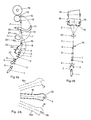
- the feeding spool 1 installed on a fixed, expandable pivot, not shown, supplies the thread 2, which unwinds according to a spiral commonly called “the balloon”.
- the thread meets the balloon-breaker 3, which contains and limits the amplitude of the balloon, and then the thread guide 4, which defines exactly the position of the thread at the entrance to the thread guided route.
- a cutting device 5 is interposed, which is symbolically indicated with a pair of scissors, but which can have a whatever configuration.
- the thread 2 finds then, along its upwards route, a pre-slub catcher 6, which is generally constituted by a slit of adjustable and preset size, for holding the clots or the coarsest imperfections, by tearing the thread.
- a pre-slub catcher 6 which is generally constituted by a slit of adjustable and preset size, for holding the clots or the coarsest imperfections, by tearing the thread.
- the point wherein the interruption of the thread occurs cannot be determined a priori , in that it necessarily occurs above the pre-slub catcher 6 due to the pulling by the upper winding-up device, and corresponds to the weakest portion of the overhanging thread. Its position, as well as the length of the free thread ends formed are hence whatever.
- the thread 2 meets - after the pre-slub catcher 6 - the thread feeler 7, which is constituted by a detector device for the thread presence. Said thread feeler 7 must "feel" the stationary thread at the beginning of the handling intervention cycle.
- the requested intervention is that of spool change and of thread joining; in the presence of the thread, on the contrary, a joining intervention only is requested.
- the device 7 is hence that which determines the type of action to be undertaken, and hence the sequence of operations to be carried out.
- the thread 2 finds then, along its upwards run, a further cutting device 8, also here symbolically indicated by a pair of cutting devices.
- the thread 2 meets subsequently a thread tensioner 9.
- Such thread tensioner device performs the function of giving the same thread a tension adjustable and ranging within preset limits, so to secure a regular cone winding up.
- the thread tensioner performs also the auxiliary function of eliminating the weak thread lengths.
- the thread tensioner device can be embodied with one or more tensioning sections, generally constituted by pairs of coaxial washers opposite to each other and urged against each other.
- a thread tensioner device capable of maintaining such tension also in the presence of irregularities in the thread is the object of the same Applicant's European patent application No. 87 202275.1.
- the thread tensioner device 9 is followed by the suction nozzle 10.
- Such suction nozzle is one of the basic components of the device, and in the process according to the present invention the nozzle 10 performs the following functions:
- the suction nozzle 10 is therefore subject to move in a direction perpendicular to the route of thread 2.
- the thread meets then the slub catcher 12.
- Such a device is one of the most important components of the coner machine, and its task is of detecting the defects of the thread 2 and of cutting the thread by means of a cutting device not shown in the figures, but substantially positioned in the same position as of the slub catcher.
- the thread 2 runs then upwards and meets a funnel-shaped member 13, which guides the same thread towards the thread guide slits 14 of the cylinder 15, which guide the turns of thread 2 on the cone 16.
- the device is completed by further handling devices and auxiliary devices.
- a further suction nozzle 21 - which, for the sake of clearness in the drawing is shown in Figure 3 - collects the thread end from the side of the feeding spool 1 in an extreme position 22 and, by revolving around the centre 23, takes it to the position 24, for it to be consigned to the knotting device 11.
- Said suction nozzle 21 can - according to a preferred form of practical embodiment - be provided in its end portion with a catching cover, which holds the thread by clamping it between the cover and the nozzle edge. This contrivance secures a reliable catch also of short-length thread ends, which otherways would not be reliably caught by the suction effect alone, and allows furthermore economies to be accomplished in the suction.
- the devices which are in contact with the thread - such as, e.g., the slub catcher 12, the thread tensioner 9 and the thread feeler 7 - are maintained clean by means of the pressurized air jet ejected from the nozzles 25.
- the handling intervention is commanded by the slub catcher, which detects the absence of the thread.
- the matter is of only intervening to join the thread; in the latter two cases, the matter is of replacing the spool and joining the free thread end of the new spool with the free thread end of the cone.
- the cone 16 and the driving cylinder 15 are preferably moved apart from each other and independently braked, in order not to damage the already coned thread. When the braking is performed, the cone and the cylinder are approached each other again.
- the thread feeler 7 closes on the thread and, should this latter be absent, gives the command for spool 1 change, which is carried out simultaneously to the first steps of the knotting cycle. If, on the contrary, the thread is present, the knotting cycle only is performed.
- the feeler 7 opens again.
- the spool change is generally automatically carried out by the same machine, which collects the new thread end and takes it to a position, on the thread route, from which it can be collected by the nozzle 21, by means of the action of devices not identified in the figure.
- the faulty spools must be replaced, like the exhausted spools. They can be processed by means of lower-productivity machines.
- the nozzle 21 is placed in its position 22 already before the operation of change of spool 1.
- the cutting device 5 cuts the free thread end of the spool to be discharged, the possible thread length above the cutting device 5 is intaken by the nozzle 21 and is removed.
- the cutting device 8 is actuated, both whether the thread is present, or not.
- the thread is present, it is subdivided into two lengths, the lower of which is removed by the nozzle 21, and the upper of which is intaken by the nozzle 10.
- the thread route up to the slub catcher is now free from thread residues.
- the nozzle 21 When the thread route is cleaned, the nozzle 21 is lifted according to the trajectory as shown by the short-dash line, to a position of non-interference for the change of the spool, and the presentation of the new free thread end.
- the upper thread end is positioned inside the knotting device.
- This task is performed by the nozzle 17, which comes to the position 19 to collect said upper thread end from the cone, and then keeps it to the position 20, as shown in Figure 3.
- the cylinder is actuated to unwind the thread length necessary for that purpose.
- the nozzle 21 brings then the new thread end to the position 24 according to the short-dash trajectory.
- such route is run along in two lengths, in the presence of limited-length thread ends; along a first, lifting, length some thread turns are unwound from the cone; the nozzle is then lowered again, so as to suck up again the unwound turns, to achieve a reliable hold, and the lifting up to position 24 is then carried out.
- the suction nozzle 10 Before the new thread end is brought to position 24, the suction nozzle 10 has performed the functions as disclosed under (a) above.
- the nozzle 10 shown in its normal position, after sucking up the thread ends and after the opening of the thread tensioner 9 and of the pre-slub catcher 6, moves to its advanced position 10A, and with the suction being continued, it extracts any dust and flock clots possibly accumulated in other devices.
- the nozzle 21 leads the thread to the position 24.
- the nozzle 10 moves back from its advanced position 10A to the retracted position 10B of Figures 3 and 4, meeting the new thread end 2 and inserting it into the thread joining unit 11.
- the thread joining unit 11 can be constituted by a mechanical knotting device, as well as by a pneumatic or friction joining device, as required.
- the hold of the thread end 2 is secured not only by the suction action, but also by a extension 26, which leads the thread to the position 2B.
- the thread is released from the knotting device, but such a release is accompanied by the nozzle 10, which controls it by means of its extension 26, moving gradually back from the position 10B to its normal position, and thus preventing loops from being formed.
- the thread feeler 7 signals the presence of the thread 2 inside it.
- the interruption is caused by the slub catcher, the thread end is however hold by the nozzle; if, on the contrary, the interruption is due to a weak point interrupted by the thread tensioner, that situation may also not occur.
- the knotting cycle takes place exactly as disclosed above, with the difference that the thread caught by the nozzle 21 is not the thread of the new spool which was replaced, but is always the same thread.
- the cutting device 5 is kept inactive and the cutting operation is entrusted to the cutting device 8 only.
- the remaining operations of the cycle are those as already disclosed referring to the intervention of spool change.
- the present invention provides for an arrangement of equipment pieces, i.e., a thread route, which accomplishes a process for thread handling and control which removes the residual lengths, remove dust and clots collected inside the components before the continuity of the thread being restored, and, when the thread continuity is restored, prevents thread loops from forming at process resumption, by means of a movable suction nozzle synchronized with it, which is moved along the route of the thread.
- equipment pieces i.e., a thread route
Landscapes
- Engineering & Computer Science (AREA)
- Textile Engineering (AREA)
- Spinning Or Twisting Of Yarns (AREA)
- Replacing, Conveying, And Pick-Finding For Filamentary Materials (AREA)
Applications Claiming Priority (2)
| Application Number | Priority Date | Filing Date | Title |
|---|---|---|---|
| IT19511/87A IT1202590B (it) | 1987-02-27 | 1987-02-27 | Dispositivo e procedimento per la manipolazione e il controllo del filo in una macchina roccatrice nelle operazioni di cambio della spola e di giunzione del filo |
| IT1951187 | 1987-02-27 |
Publications (2)
| Publication Number | Publication Date |
|---|---|
| EP0281183A1 true EP0281183A1 (fr) | 1988-09-07 |
| EP0281183B1 EP0281183B1 (fr) | 1992-04-22 |
Family
ID=11158655
Family Applications (1)
| Application Number | Title | Priority Date | Filing Date |
|---|---|---|---|
| EP88200285A Expired EP0281183B1 (fr) | 1987-02-27 | 1988-02-17 | Dispositif et procédé pour la manipulation et la commande du fil d'une machine de bobinage à cônes pendant les opérations de remplacement de bobine et de rattachement du fil |
Country Status (4)
| Country | Link |
|---|---|
| EP (1) | EP0281183B1 (fr) |
| DE (1) | DE3870282D1 (fr) |
| ES (1) | ES2032943T3 (fr) |
| IT (1) | IT1202590B (fr) |
Cited By (1)
| Publication number | Priority date | Publication date | Assignee | Title |
|---|---|---|---|---|
| WO2013138944A1 (fr) * | 2012-03-21 | 2013-09-26 | Uster Technologies Ag | Tendeur de fil à disques comprenant un dispositif de nettoyage |
Families Citing this family (1)
| Publication number | Priority date | Publication date | Assignee | Title |
|---|---|---|---|---|
| DE102008013108A1 (de) * | 2008-03-07 | 2009-09-17 | Oerlikon Textile Gmbh & Co. Kg | Arbeitsstelle eines Kreuzspulautomaten |
Citations (11)
| Publication number | Priority date | Publication date | Assignee | Title |
|---|---|---|---|---|
| DE912193C (de) * | 1942-01-28 | 1954-05-28 | Schlafhorst & Co W | Spulmaschine mit voneinander unabhaengigen ortsfesten Spulstellen |
| DE920055C (de) * | 1941-10-18 | 1954-11-11 | Schlafhorst & Co W | Verfahren und Einrichtung zum Zufuehren von Fadenenden an selbsttaetigen Spulmaschinen |
| CH441078A (de) * | 1966-06-01 | 1967-07-31 | Schweiter Ag Maschf | Knotvorrichtung an einer automatischen Spulmaschine |
| US3399840A (en) * | 1965-12-09 | 1968-09-03 | Hayashi Junichi | Winding machine for winding yarns or the like materials into cheese or cones |
| US3834634A (en) * | 1970-04-30 | 1974-09-10 | Elitex Zavody Textilniho | Method of controlling the knotting procedure in textile machines, particularly automatic winding machines and pneumatic circuit for performing said method |
| DE2404035A1 (de) * | 1974-01-29 | 1975-08-07 | Schlafhorst & Co W | Automatische kreuzspulmaschine |
| DE2543983B1 (de) * | 1975-10-02 | 1976-12-02 | Mayer Fa Karl | Garnpruefvorrichtung fuer Textilmaschinen |
| DE2705080A1 (de) * | 1977-02-08 | 1978-08-10 | Mayer Fa Karl | Kreuzspulautomat |
| DE2824752A1 (de) * | 1978-06-06 | 1979-12-13 | Schlafhorst & Co W | Spulmaschine fuer textilfaeden |
| DE3213631A1 (de) * | 1981-04-13 | 1982-10-28 | Murata Kikai K.K., Kyoto | Steuereinrichtung fuer das abnehmen einer spule aus einem spulautomaten |
| DE3241280C1 (de) * | 1982-11-09 | 1984-06-14 | Karl Mayer Textil-Maschinen-Fabrik Gmbh, 6053 Obertshausen | Automatische Spulmaschine |
-
1987
- 1987-02-27 IT IT19511/87A patent/IT1202590B/it active
-
1988
- 1988-02-17 ES ES198888200285T patent/ES2032943T3/es not_active Expired - Lifetime
- 1988-02-17 EP EP88200285A patent/EP0281183B1/fr not_active Expired
- 1988-02-17 DE DE8888200285T patent/DE3870282D1/de not_active Expired - Fee Related
Patent Citations (11)
| Publication number | Priority date | Publication date | Assignee | Title |
|---|---|---|---|---|
| DE920055C (de) * | 1941-10-18 | 1954-11-11 | Schlafhorst & Co W | Verfahren und Einrichtung zum Zufuehren von Fadenenden an selbsttaetigen Spulmaschinen |
| DE912193C (de) * | 1942-01-28 | 1954-05-28 | Schlafhorst & Co W | Spulmaschine mit voneinander unabhaengigen ortsfesten Spulstellen |
| US3399840A (en) * | 1965-12-09 | 1968-09-03 | Hayashi Junichi | Winding machine for winding yarns or the like materials into cheese or cones |
| CH441078A (de) * | 1966-06-01 | 1967-07-31 | Schweiter Ag Maschf | Knotvorrichtung an einer automatischen Spulmaschine |
| US3834634A (en) * | 1970-04-30 | 1974-09-10 | Elitex Zavody Textilniho | Method of controlling the knotting procedure in textile machines, particularly automatic winding machines and pneumatic circuit for performing said method |
| DE2404035A1 (de) * | 1974-01-29 | 1975-08-07 | Schlafhorst & Co W | Automatische kreuzspulmaschine |
| DE2543983B1 (de) * | 1975-10-02 | 1976-12-02 | Mayer Fa Karl | Garnpruefvorrichtung fuer Textilmaschinen |
| DE2705080A1 (de) * | 1977-02-08 | 1978-08-10 | Mayer Fa Karl | Kreuzspulautomat |
| DE2824752A1 (de) * | 1978-06-06 | 1979-12-13 | Schlafhorst & Co W | Spulmaschine fuer textilfaeden |
| DE3213631A1 (de) * | 1981-04-13 | 1982-10-28 | Murata Kikai K.K., Kyoto | Steuereinrichtung fuer das abnehmen einer spule aus einem spulautomaten |
| DE3241280C1 (de) * | 1982-11-09 | 1984-06-14 | Karl Mayer Textil-Maschinen-Fabrik Gmbh, 6053 Obertshausen | Automatische Spulmaschine |
Cited By (2)
| Publication number | Priority date | Publication date | Assignee | Title |
|---|---|---|---|---|
| WO2013138944A1 (fr) * | 2012-03-21 | 2013-09-26 | Uster Technologies Ag | Tendeur de fil à disques comprenant un dispositif de nettoyage |
| CH706263A1 (de) * | 2012-03-21 | 2013-09-30 | Uster Technologies Ag | Tellerfadenbremse mit Reinigungseinrichtung. |
Also Published As
| Publication number | Publication date |
|---|---|
| ES2032943T3 (es) | 1993-03-01 |
| EP0281183B1 (fr) | 1992-04-22 |
| DE3870282D1 (de) | 1992-05-27 |
| IT8719511A0 (it) | 1987-02-27 |
| IT1202590B (it) | 1989-02-09 |
Similar Documents
| Publication | Publication Date | Title |
|---|---|---|
| US4083171A (en) | Method and apparatus for eliminating an abnormality in a thread to be wound onto the bobbin of an open-end spinning device | |
| US5651507A (en) | Yarn splicing device for bobbin-winding textile machines | |
| US5681000A (en) | Servicing apparatus for a yarn package-producing textile machine | |
| US4511095A (en) | Method and apparatus for winding glass fibers | |
| US5109662A (en) | Operating method and apparatus for the automated removal of yarn remnants from winding tubes by an automated maintenance and servicing device traveling along a textile yarn processing machine | |
| US5115629A (en) | Method and apparatus for preparing yarn ends to be spliced | |
| US5012844A (en) | Weft yarn threading device for a jet loom | |
| GB1466421A (en) | Bobbin changing method and apparatus | |
| US5136833A (en) | Method and apparatus for removing yarn package and transport adapter from a spindle assembly of a yarn processing machine and securing the free end portion of yarn for transport | |
| US4832091A (en) | Method and mechanism for repairing the weft supply on weaving machines in case of an interruption between the supply package and the weft accumulator | |
| US5188304A (en) | Device and process for the handling and the control of the thread on a coner machine during the operation of spool change and of thread joining | |
| US3942731A (en) | Method and apparatus for forming reserve windings during a bobbin change on a spinning machine | |
| US4321736A (en) | Apparatus for extending a warp fed to a tufting machine | |
| CN1266018C (zh) | 除去供应给自动络纱机的卷装上的纱的有缺陷端部的装置及方法 | |
| EP0281183A1 (fr) | Dispositif et procédé pour la manipulation et la commande du fil d'une machine de bobinage à cônes pendant les opérations de remplacement de bobine et de rattachement du fil | |
| JP4395828B2 (ja) | 張力検出器を備える糸条巻取機 | |
| US5090189A (en) | Method and apparatus for preparing a yarn package for a subsequent yarn restarting operation | |
| US4646981A (en) | Process and apparatus for the simultaneous throwing of several textile threads delivered continuously | |
| JPS63310468A (ja) | 自動ワインダ− | |
| KR100562378B1 (ko) | 방사권취기 및 그 번치권취방법 | |
| US4998566A (en) | Liquid warp splicing system for a warp in a loom | |
| JP2019199363A (ja) | 糸継ぎされる糸片と排出される糸片を分離する方法、加圧ローラユニット及び吸引ノズル | |
| US4339089A (en) | Yarn winding apparatus and method | |
| US5992790A (en) | Method of finishing reels | |
| DE19858986A1 (de) | Bedienaggregat für eine Faserband verarbeitende Textilmaschine |
Legal Events
| Date | Code | Title | Description |
|---|---|---|---|
| PUAI | Public reference made under article 153(3) epc to a published international application that has entered the european phase |
Free format text: ORIGINAL CODE: 0009012 |
|
| AK | Designated contracting states |
Kind code of ref document: A1 Designated state(s): CH DE ES FR GB LI |
|
| 17P | Request for examination filed |
Effective date: 19890209 |
|
| 17Q | First examination report despatched |
Effective date: 19900824 |
|
| GRAA | (expected) grant |
Free format text: ORIGINAL CODE: 0009210 |
|
| AK | Designated contracting states |
Kind code of ref document: B1 Designated state(s): CH DE ES FR GB LI |
|
| ET | Fr: translation filed | ||
| REF | Corresponds to: |
Ref document number: 3870282 Country of ref document: DE Date of ref document: 19920527 |
|
| PG25 | Lapsed in a contracting state [announced via postgrant information from national office to epo] |
Ref country code: ES Free format text: LAPSE BECAUSE OF NON-PAYMENT OF DUE FEES Effective date: 19930218 |
|
| PLBE | No opposition filed within time limit |
Free format text: ORIGINAL CODE: 0009261 |
|
| STAA | Information on the status of an ep patent application or granted ep patent |
Free format text: STATUS: NO OPPOSITION FILED WITHIN TIME LIMIT |
|
| REG | Reference to a national code |
Ref country code: ES Ref legal event code: FG2A Ref document number: 2032943 Country of ref document: ES Kind code of ref document: T3 |
|
| 26N | No opposition filed | ||
| REG | Reference to a national code |
Ref country code: ES Ref legal event code: FD2A Effective date: 19990301 |
|
| REG | Reference to a national code |
Ref country code: CH Ref legal event code: PUE Owner name: SAVIO S.P.A. TRANSFER- SAVIO MACCHINE TESSILI S.P. |
|
| REG | Reference to a national code |
Ref country code: FR Ref legal event code: TP |
|
| REG | Reference to a national code |
Ref country code: GB Ref legal event code: 732E |
|
| PGFP | Annual fee paid to national office [announced via postgrant information from national office to epo] |
Ref country code: GB Payment date: 20010214 Year of fee payment: 14 |
|
| REG | Reference to a national code |
Ref country code: GB Ref legal event code: IF02 |
|
| PG25 | Lapsed in a contracting state [announced via postgrant information from national office to epo] |
Ref country code: GB Free format text: LAPSE BECAUSE OF NON-PAYMENT OF DUE FEES Effective date: 20020217 |
|
| GBPC | Gb: european patent ceased through non-payment of renewal fee |
Effective date: 20020217 |
|
| PGFP | Annual fee paid to national office [announced via postgrant information from national office to epo] |
Ref country code: FR Payment date: 20030210 Year of fee payment: 16 |
|
| PGFP | Annual fee paid to national office [announced via postgrant information from national office to epo] |
Ref country code: CH Payment date: 20040218 Year of fee payment: 17 |
|
| PGFP | Annual fee paid to national office [announced via postgrant information from national office to epo] |
Ref country code: DE Payment date: 20040226 Year of fee payment: 17 |
|
| PG25 | Lapsed in a contracting state [announced via postgrant information from national office to epo] |
Ref country code: FR Free format text: LAPSE BECAUSE OF NON-PAYMENT OF DUE FEES Effective date: 20041029 |
|
| REG | Reference to a national code |
Ref country code: FR Ref legal event code: ST |
|
| PG25 | Lapsed in a contracting state [announced via postgrant information from national office to epo] |
Ref country code: LI Free format text: LAPSE BECAUSE OF NON-PAYMENT OF DUE FEES Effective date: 20050228 Ref country code: CH Free format text: LAPSE BECAUSE OF NON-PAYMENT OF DUE FEES Effective date: 20050228 |
|
| PG25 | Lapsed in a contracting state [announced via postgrant information from national office to epo] |
Ref country code: DE Free format text: LAPSE BECAUSE OF NON-PAYMENT OF DUE FEES Effective date: 20050901 |
|
| REG | Reference to a national code |
Ref country code: CH Ref legal event code: PL |