EP0281243B1 - Dispositif d'empilage pour fils souples - Google Patents
Dispositif d'empilage pour fils souples Download PDFInfo
- Publication number
- EP0281243B1 EP0281243B1 EP88300777A EP88300777A EP0281243B1 EP 0281243 B1 EP0281243 B1 EP 0281243B1 EP 88300777 A EP88300777 A EP 88300777A EP 88300777 A EP88300777 A EP 88300777A EP 0281243 B1 EP0281243 B1 EP 0281243B1
- Authority
- EP
- European Patent Office
- Prior art keywords
- strand
- stretch
- wire
- conveyor
- endwise
- Prior art date
- Legal status (The legal status is an assumption and is not a legal conclusion. Google has not performed a legal analysis and makes no representation as to the accuracy of the status listed.)
- Expired - Lifetime
Links
- 238000006073 displacement reaction Methods 0.000 claims description 13
- 230000004888 barrier function Effects 0.000 claims description 5
- 230000004044 response Effects 0.000 claims description 5
- 230000000694 effects Effects 0.000 claims description 3
- 239000004020 conductor Substances 0.000 description 8
- 230000007246 mechanism Effects 0.000 description 6
- 238000009413 insulation Methods 0.000 description 4
- 238000000034 method Methods 0.000 description 2
- 230000000717 retained effect Effects 0.000 description 2
- 208000027418 Wounds and injury Diseases 0.000 description 1
- 238000010276 construction Methods 0.000 description 1
- 230000006378 damage Effects 0.000 description 1
- 239000004744 fabric Substances 0.000 description 1
- 230000005484 gravity Effects 0.000 description 1
- 208000014674 injury Diseases 0.000 description 1
- 239000000463 material Substances 0.000 description 1
- 230000008569 process Effects 0.000 description 1
Images




Classifications
-
- B—PERFORMING OPERATIONS; TRANSPORTING
- B65—CONVEYING; PACKING; STORING; HANDLING THIN OR FILAMENTARY MATERIAL
- B65G—TRANSPORT OR STORAGE DEVICES, e.g. CONVEYORS FOR LOADING OR TIPPING, SHOP CONVEYOR SYSTEMS OR PNEUMATIC TUBE CONVEYORS
- B65G57/00—Stacking of articles
- B65G57/02—Stacking of articles by adding to the top of the stack
- B65G57/16—Stacking of articles of particular shape
- B65G57/18—Stacking of articles of particular shape elongated, e.g. sticks, rods, bars
- B65G57/186—Cylindrical articles, e.g. tubes, rods, etc.
-
- B—PERFORMING OPERATIONS; TRANSPORTING
- B21—MECHANICAL METAL-WORKING WITHOUT ESSENTIALLY REMOVING MATERIAL; PUNCHING METAL
- B21D—WORKING OR PROCESSING OF SHEET METAL OR METAL TUBES, RODS OR PROFILES WITHOUT ESSENTIALLY REMOVING MATERIAL; PUNCHING METAL
- B21D43/00—Feeding, positioning or storing devices combined with, or arranged in, or specially adapted for use in connection with, apparatus for working or processing sheet metal, metal tubes or metal profiles; Associations therewith of cutting devices
- B21D43/28—Associations of cutting devices therewith
- B21D43/285—Devices for handling elongated articles, e.g. bars, tubes or profiles
-
- H—ELECTRICITY
- H01—ELECTRIC ELEMENTS
- H01R—ELECTRICALLY-CONDUCTIVE CONNECTIONS; STRUCTURAL ASSOCIATIONS OF A PLURALITY OF MUTUALLY-INSULATED ELECTRICAL CONNECTING ELEMENTS; COUPLING DEVICES; CURRENT COLLECTORS
- H01R43/00—Apparatus or processes specially adapted for manufacturing, assembling, maintaining, or repairing of line connectors or current collectors or for joining electric conductors
- H01R43/28—Apparatus or processes specially adapted for manufacturing, assembling, maintaining, or repairing of line connectors or current collectors or for joining electric conductors for wire processing before connecting to contact members, not provided for in groups H01R43/02 - H01R43/26
-
- Y—GENERAL TAGGING OF NEW TECHNOLOGICAL DEVELOPMENTS; GENERAL TAGGING OF CROSS-SECTIONAL TECHNOLOGIES SPANNING OVER SEVERAL SECTIONS OF THE IPC; TECHNICAL SUBJECTS COVERED BY FORMER USPC CROSS-REFERENCE ART COLLECTIONS [XRACs] AND DIGESTS
- Y10—TECHNICAL SUBJECTS COVERED BY FORMER USPC
- Y10T—TECHNICAL SUBJECTS COVERED BY FORMER US CLASSIFICATION
- Y10T29/00—Metal working
- Y10T29/51—Plural diverse manufacturing apparatus including means for metal shaping or assembling
- Y10T29/5136—Separate tool stations for selective or successive operation on work
- Y10T29/5137—Separate tool stations for selective or successive operation on work including assembling or disassembling station
- Y10T29/5139—Separate tool stations for selective or successive operation on work including assembling or disassembling station and means to sever work prior to disassembling
- Y10T29/514—Separate tool stations for selective or successive operation on work including assembling or disassembling station and means to sever work prior to disassembling comprising means to strip insulation from wire
-
- Y—GENERAL TAGGING OF NEW TECHNOLOGICAL DEVELOPMENTS; GENERAL TAGGING OF CROSS-SECTIONAL TECHNOLOGIES SPANNING OVER SEVERAL SECTIONS OF THE IPC; TECHNICAL SUBJECTS COVERED BY FORMER USPC CROSS-REFERENCE ART COLLECTIONS [XRACs] AND DIGESTS
- Y10—TECHNICAL SUBJECTS COVERED BY FORMER USPC
- Y10T—TECHNICAL SUBJECTS COVERED BY FORMER US CLASSIFICATION
- Y10T29/00—Metal working
- Y10T29/51—Plural diverse manufacturing apparatus including means for metal shaping or assembling
- Y10T29/5187—Wire working
-
- Y—GENERAL TAGGING OF NEW TECHNOLOGICAL DEVELOPMENTS; GENERAL TAGGING OF CROSS-SECTIONAL TECHNOLOGIES SPANNING OVER SEVERAL SECTIONS OF THE IPC; TECHNICAL SUBJECTS COVERED BY FORMER USPC CROSS-REFERENCE ART COLLECTIONS [XRACs] AND DIGESTS
- Y10—TECHNICAL SUBJECTS COVERED BY FORMER USPC
- Y10T—TECHNICAL SUBJECTS COVERED BY FORMER US CLASSIFICATION
- Y10T83/00—Cutting
- Y10T83/202—With product handling means
- Y10T83/2092—Means to move, guide, or permit free fall or flight of product
- Y10T83/2183—Product mover including gripper means
- Y10T83/2187—Reciprocating product handler
-
- Y—GENERAL TAGGING OF NEW TECHNOLOGICAL DEVELOPMENTS; GENERAL TAGGING OF CROSS-SECTIONAL TECHNOLOGIES SPANNING OVER SEVERAL SECTIONS OF THE IPC; TECHNICAL SUBJECTS COVERED BY FORMER USPC CROSS-REFERENCE ART COLLECTIONS [XRACs] AND DIGESTS
- Y10—TECHNICAL SUBJECTS COVERED BY FORMER USPC
- Y10T—TECHNICAL SUBJECTS COVERED BY FORMER US CLASSIFICATION
- Y10T83/00—Cutting
- Y10T83/202—With product handling means
- Y10T83/2092—Means to move, guide, or permit free fall or flight of product
- Y10T83/2192—Endless conveyor
- Y10T83/2194—And means to remove product therefrom
-
- Y—GENERAL TAGGING OF NEW TECHNOLOGICAL DEVELOPMENTS; GENERAL TAGGING OF CROSS-SECTIONAL TECHNOLOGIES SPANNING OVER SEVERAL SECTIONS OF THE IPC; TECHNICAL SUBJECTS COVERED BY FORMER USPC CROSS-REFERENCE ART COLLECTIONS [XRACs] AND DIGESTS
- Y10—TECHNICAL SUBJECTS COVERED BY FORMER USPC
- Y10T—TECHNICAL SUBJECTS COVERED BY FORMER US CLASSIFICATION
- Y10T83/00—Cutting
- Y10T83/202—With product handling means
- Y10T83/2092—Means to move, guide, or permit free fall or flight of product
- Y10T83/22—Means to move product laterally
- Y10T83/2205—Reciprocating means
Definitions
- This invention relates generally to handling of flexible wire strands such as wire strands as used in wire harnesses, and for other purposes; more specifically it concerns stacking of such strands, as for example flimsy wire strands, which have been cut to length, and/or stripped of insulation at strand ends, in conjunction with such cutting and/or stripping.
- U.S. Patent No. 4,266,455 describes a long-sized wire transfer apparatus for use with a wire cutting machine or the like including a wire feed mechanism and a cutter blade assembly which opens and closes to cut into predetermined lengths a wire intermitently fed in by the wire feed mechanism.
- the wire transfer apparatus comprises a wire clamping transfer conveyor laterally extending from the downstream side of the cutter blade assembly in a direction at the right angles to the wire withdrawing line, a wire drift conveyor composed of an endless belt extending laterally from the initial end of the transfer conveyor through a slide plate of suitable length along the wire withdrawing line, and a wire collecting device or the like disposed immediately below the terminal end of the wire clamping transfer conveyor.
- US Patent No. 3,869,781 describes apparatus for attaching terminals to electric conductors, wherein the electric conductors are cut to predetermined length in a wire cutting and stripping device in which stripping jaws of the insulation stripping mechanism, which grip the cut-off length of conductor, are mounted on a rectilinearly movable panel in a conductor supply zone, so that upon being moved, the cut-off conductor will be carried by a translatory movement into a position where it is engaged by the jaws of a pair of conveyor fingers and carried to a terminal attaching zone where an end of the cut-off conductor is positioned in a conductor end receiving portion of the terminal which is then secured to the conductor end by the operation of appropriate dies embodied in an associated terminal attaching device.
- One object of the present invention is to enable the handling and stacking of elongate strands whilst avoiding the above problems and other problems encountered in automatic processing of wire of different sizes, lengths and flimsiness.
- a flexible strand stacker comprises a flexible strand stacker comprising conveyor means having an elongate endwise travelling stretch onto which a strand is fed to be carried endwise on the stretch, gripper means to grip a trailing portion of the strand as the forward extent of the strand is carried endwise on the stretch and holder means to temporarily and locally hold the trailing portion of the strand to the travelling conveyor means stretch and to travel therewith, until the strand is endwise positioned for the gripper means to effect displacement of the gripper means to a position locating the gripped portion of the strand sufficiently out of alignment with the stretch so that the strand is progressively pulled sidewardly off the stretch in response to endwise travel of the stretch relative to the strand, the holder means being located to temporarily hold a portion of the strand proximate that portion of the travelling stretch closest to the path of the displacement of the gripper means and is characterised by spaced flexible barrier fingers mounted for travelling movement with the stretch and so positioned as to initially block sideward displacement of the strand and to urge
- the gripper means is typically moved linearly, transversely of wire strand travel to effect displacement of the gripper means to a position locating the gripped portion of the strand sufficiently out of alignment with the stretch that the strand is progressively pulled sidewardly off the stretch in response to endwise travel of the stretch relative to the strand.
- the gripper means may typically comprise a clamp having a first position in which the clamp operates to grip the trailing portion of the strand as the strand travels past the gripper means, and a second position linearly spaced from said first position and in which the clamp continues to grip the strand until it is pulled free of the stretch, the strand then being released for stacking; and more particularly immediately after the wire is gripped and positioned linearly for peel-off from the conveyor, the next wire can be fed down the conveyor thus maintaining maximum through-put.
- the gripper is designed to position over the next moving wire after releasing the prior wire at the appropriate time for accurate stacking, and a suitable control is provided for timing.
- the gripper means may comprise:
- means is provided to feed the wire strand for travel toward the gripper means and conveyor means, and the wire is typically cut to length as it is so fed.
- a still further object includes the provision of barrier fingers travelling with said stretch and positioned to urge the strand off the stretch and the stretch travels endwise relative to the strand during gripping of the strand by the gripper means at a location out of alignment with the stretch.
- Such fingers initially act to block sideward displacement of the strand off the stretch and they may be attached to the conveyor belt, and are flexible and bendable so as not to injure the wire strand being pulled off the conveyor. Also, the fingers can be easily replaced in the field if worn or damaged.
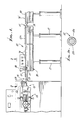
- conveyor means 10 has an elongated endwise travelling upper stretch 11a onto which a wire strand 12 is fed to be carried endwise (to the right in Figure 1) on that stretch, in frictional contact with same.
- the conveyor may comprise an endless belt 11 of tough fabric material acting to frictionally retain and transport the wire on the top surface of belt upper stretch 11a, which travels rightwardly in Figure 1.
- a typical flimsy wire strand 12 has a cross section that includes a metallic wire core 12a, and non-metallic insulation sheath 12b about the core.
- the conveyor means 10 also includes lengthwise spaced rollers 13 and 14 about which the belt 11 is entrained, the belt including upper stretch 11a sliding on a support table 15, and the belt lower stretch 11b travelling below that table.
- Frame structure 16 carries the table and rollers, and is in turn supported by standards 17.
- a drive for the conveyor includes motor 18, pulley 19 carried by the motor shaft 18a, pulley 20 carried by shaft 13a attached to roller 13, and belt 21 entrained on pulleys 19 and 20.
- the wire strand 12 is fed onto the belt upper stretch 11a in a rightward direction in Figures 1 and 4, to be carried rightwardly on that stretch.
- Apparatus to feed the wire to the belt is indicated generally in Figure 1 to include wire feeding, cutting, and insulation stripping mechanism 23, and elongated wire guide mechanism 24. Cutting and stripping of the selected wire strand length at its trailing end is effected by means indicated at 25. Forwardly of that location, the wire travels forwardly within the guide mechanism 24, better seen in Figures 2 and 5, extending generally toward the conveyor means.
- the guide means 24 includes a tubular guide 27 to receive the wire strand.
- An outer guide tube 29 is also provided to slidably receive the inner guide tube. It is shown as having a retracted position in Figures 2 and 4, and an advanced position in Figure 5, the wire strand being guided by the scalloped forward end 29a in that view.
- An actuator for the outer guide tube 29 is indicated at 28 in Figures 1 and 2. Tube connects to actuator 28 at 129.
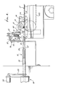
- the gripper means 40 serves to grip a trailing portion of the strand as forward extent of the strand is carried endwise on the conveyor upper stretch 11a. See for example Figures 3 and 6 wherein the gripper grips wire strand extent 12, first at its forward travel location 12c, in Figure 3, and also as the strand selection is displaced linearly sidewardly to location 12d, in Figure 6, enabling the strand on the conveyor to be pulled off the conveyor as by travel of barrier fingers on the conveyor. Note that as the strand is displaced from travel position 12c to location 12d, the strand is positively pulled or displaced sidewardly thereby to be positioned to be pulled off the conveyor and to drop by gravity into the trough, when the gripper means releases the wire strand. See in Figure 6 the released wire strands 12e dropping into the trough or collector 30.
- a holer means such as clamp roller 31 has a first or “down” position (see Figure 7) in which it grips the trailing portion 12f of the strand 12 so that trailing portion passes the gripper means prior to being gripped, thereby to hold the cut strand to the conveyor to travel therewith until the cut strand is in position to be gripped by gripper 40; also the holder has second or “up” position (see Figure 4) to stop endwise feeding of the strand by the conveyor. See actuator 32 having arm 32a connected to a lever 33 pivotally mounting roller 31 at 33. A lever mouting pivot is shown at 34. Spring 35 urges the lever upwardly.
- the gripper means also advantageously includes a carrier mounted by guide rods 45 on a fixed frame 46 for lateral movement.
- the carrier 44 carries two gripper jaws 47 and 48, for downward and closing together movement to grip opposite sides of the strand 12c.
- Jaws 47 and 48 are pivotally mounted to the carrier at locations 49 and 50, and spur gears 51 and 52 are pivotable with the jaws.
- actuator 53 carried by frame 44 extends its arm 53a, it rotates jaw arm 47a, to pivot jaw 47 counterclockwise toward one side of the strand 12c, and simultaneously jaw 48 is pivoted clockwise by the gears to close against the opposite side of the strand.
- Actuator 55 on the frame then displaces the carrier 44 to the left from Figure 3 to Figure 6 position, as described. After reaching Figure 6 position, the jaws maintain the gripped wire strand at 12d in that position until the strand has been detrained sidewise off the conveyor, to drop into the collector
- FIG. 5 shows that when the strand is gripped and displaced to position 12d by the gripper means, a finger 70 is carried up by roller 13 and the conveyor to approach the laterally deviated portion 12f of the strand, so that as that finger 70 then travels forwardly with the stretch in direction 72, the strand is progressively displaced or pulled in direction 73 away from the stretch, i.e. the strand is pulled off the stretch to drop into the collector.
- Multiple fingers 70 are mounted at 75 to the conveyor belt, adjacent the edge 76 thereof off which the strand is to be pulled or displaced.
- the fingers are flexible, or they are flexibly mounted, so as to bend relative to the belt, whereby risk of injury to the strand during pull off the stretch is eliminated.
- a second conveyor may be provided as indicated at 80 in Figure 1, and may have the same construction and drive as the first conveyor.
- the end-to-end conveyors are of a length to accommodate strands of chosen length.
- strands may also apply to other flimsy, elongated, narrow, flexible bodies such as ropes, cords, tubes and the like.
- the basic stacking method of the invention involves the following steps:
- tubular guide 29 is slot lengthwise along side 29b, to pass the wire being displaced by the clamps 47 and 48.
- fingers 70 ⁇ on the additional conveyor 80 are typically offset laterally in their travel path from the fingers 70 on the first conveyor means so as to ensure lateral pull off the strand from the second conveyor, into the trough.
- the fingers 70 ⁇ may be at the opposite side of the strand 12, relative to fingers 70.
Landscapes
- Engineering & Computer Science (AREA)
- Mechanical Engineering (AREA)
- Manufacturing & Machinery (AREA)
- Winding, Rewinding, Material Storage Devices (AREA)
- Forwarding And Storing Of Filamentary Material (AREA)
- Basic Packing Technique (AREA)
Claims (11)
- Dispositif d'empilage de fils souples, comprenant des moyens de transport (10) qui comportent une bande sans fin allongée en mouvement (11a,11b) sur laquelle on amène un fil (12) afin de le transporter longitudinalement sur la bande (11a,11b), des moyens de prise (40) pour saisir une partie arrière du fil (12) tandis que la partie avant du fil (12) est transportée longitudinalement sur la bande (11a,11b), et des moyens de maintien (31) pour tenir temporairement et localement la partie arrière du fil (12) sur la bande transporteuse en mouvement (11a,11b) afin que le fil se déplace avec celle-ci jusqu'à ce que le fil (12) soit positionné longitudinalement pour que les moyens de prise saisissent la partie arrière du fil (12), des moyens (55) de déplacement des moyens de prise (40) à une position qui situe la partie saisie du fil (12) suffisamment hors d'alignement avec la bande (11a,11b) pour que le fil (12) soit progressivement tiré latéralement hors de la bande (11a, 11b) en réponse au déplaceemnt longitudinal de la bande (11a,11b) par rapport au fil (12), les moyens de maintien (31) étant situés de manière à tenir temporairement une partie du fil (12) près de la partie de la bande en mouvement (11a,11b) qui est la plus proche du chemin de déplacement des moyens de prise (40), caractérisé en ce que des doigts d'arrêt flexibles espacés (70) sont montés de manière à se déplacer avec la bande (11a,11b) et ils sont positionnés de manière à empêcher initialement le déplacement latéral du fil (12) et à pousser le fil (12) hors de la bande (11a,11b) lorsque la bande (11a, 11b) se déplace longitudinalement par rapport au fil (12) pendant que le fil (12) est saisi à la position hors d'alignement avec la bande (11a,11b).
- Dispositif d'empilage suivant la revendication 1, caractérisé en ce que les moyens de déplacement (55) des moyens de prise sont situés de manière à saisir une partie arrière du fil (12) qui n'a pas encore été amenée sur la bande (11a,11b), et en ce que les moyens de maintien (31) comprennent un rouleau (31) qui peut se rapprocher et s'éloigner de façon intermittente d'une partie de la bande (11a,11b) sur les moyens de transport.
- Dispositif d'empilage suivant la revendication 1 ou 2, caractérisé en ce que les moyens de prise (40) comprennent une pince (47,48) ayant une première position, dans laquelle la pince fonctionne pour saisir la partie arrière du fil lorsque le fil passe devant les moyens de prise, et une deuxième position linéairement espacée de la première position et dans laquelle la pince relâche le fil, pour son empilage.
- Dispositif d'empilage suivant la revendication 3, caractérisé en ce qu'un collecteur (30) est monté à un niveau inférieur à celui de la bande (11a, 11b), et le fil tombe dans ce collecteur lorsqu'il est relâché par la pince (47,48).
- Dispositif d'empilage suivant une quelconque des revendications 1 à 4, caractérisé en ce qu'il comprend des moyens de coupe (25) pour couper le fil à une longueur prédéterminée lorsque le fil est avancé sur la bande.
- Dispositif d'empilage suivant la revendication 5, caractérisé en ce qu'il comprend des moyens (10) d'amenée du fil vers les moyens de prise (47,48) et la dite bande, qui comportent un guidage tubulaire fendu latéralement (24).
- Dispositif d'empilage suivant une quelconque des revendications précédentes, caractérisé en ce que le fil est un conducteur métallique peu rigide.
- Dispositif d'empilage suivant la revendication 4, caractérisé en ce qu'il comprend un premier guidage tubulaire (27) pour recevoir le fil (12) ; le guidage tubulaire (27) ayant une position avancée, dans laquelle le fil est amené sur les moyens de transport (10), et une position rétractée dans laquelle le guidage tubulaire est en dehors du chemin de déplacement linéaire de la pince (47,48), un deuxième guidage tubulaire extérieur (29) qui reçoit le premier guidage tubulaire (27) et qui a une position avancée lorsque le guidage tubulaire (27) est rétracté, le deuxième guidage tubulaire (29) ayant une extrémité avant inclinée pour agir comme un guidage de fil pendant la traction de la partie avant du fil latéralement, hors des moyens de transport.
- Dispositif d'empilage suivant la revendication 8, comprenant un actionneur (28) qui fonctionne pour déplacer le premier guidage tubulaire (27) entre la position avancée et la position rétractée.
- Dispositif d'emballage suivant la revendication 1, caractérisé en ce que les moyens de prise (40) comprennent :i- un chariot (44) déplaçable linéairement dans la direction transversale, et des mâchoires (47,48) pouvant pivoter l'une par rapport à l'autre et portées par le chariot (44), etii- des moyens de manoeuvre (53) fonctionnellement reliés aux mâchoires pivotantes (47,48) pour les déplacer entre des positions de prise et de libération du fil lorsque le chariot (44) est déplacé linéairement dans la direction transversale.
- Dispositif suivant la revendication 10, comprenant des moyens de transport additionnels (80) placés au-delà des moyens de transport cités en premier (10), des doigts (70') prévus sur les moyens de transport additionnels (80) étant décalés , dans leur trajectoire, par rapport à la trajectoire des doigts (70) prévus sur les moyens de transport cités en premier (10).
Applications Claiming Priority (2)
| Application Number | Priority Date | Filing Date | Title |
|---|---|---|---|
| US07/022,982 US4765053A (en) | 1987-03-06 | 1987-03-06 | Wire strand stacker |
| US22982 | 1987-03-06 |
Publications (2)
| Publication Number | Publication Date |
|---|---|
| EP0281243A1 EP0281243A1 (fr) | 1988-09-07 |
| EP0281243B1 true EP0281243B1 (fr) | 1993-08-11 |
Family
ID=21812449
Family Applications (1)
| Application Number | Title | Priority Date | Filing Date |
|---|---|---|---|
| EP88300777A Expired - Lifetime EP0281243B1 (fr) | 1987-03-06 | 1988-01-29 | Dispositif d'empilage pour fils souples |
Country Status (3)
| Country | Link |
|---|---|
| US (1) | US4765053A (fr) |
| EP (1) | EP0281243B1 (fr) |
| DE (1) | DE3883025T2 (fr) |
Families Citing this family (4)
| Publication number | Priority date | Publication date | Assignee | Title |
|---|---|---|---|---|
| FR2664757A1 (fr) * | 1990-07-10 | 1992-01-17 | Balan Sa J | Dispositif de stockage temporaire de fils electriques et machine de mise en faisceau de fils electriques utilisant ce dispositif. |
| DE59304101D1 (de) * | 1992-08-27 | 1996-11-14 | Komax Holding Ag | Kabelbündelungseinrichtung für Kabelverarbeitungsmaschinen |
| US6694585B2 (en) * | 2002-05-16 | 2004-02-24 | L&P Property Management Company | Apparatus and method for securing end turns of coil springs to a border wire |
| KR20230152711A (ko) * | 2021-03-09 | 2023-11-03 | 쉴로이니게르 아게 | 케이블 스태커, 케이블 스태커를 포함하는 케이블 처리장치 및 케이블을 안전하게 운반하는 방법 |
Family Cites Families (12)
| Publication number | Priority date | Publication date | Assignee | Title |
|---|---|---|---|---|
| US3869781A (en) * | 1974-02-25 | 1975-03-11 | Eubanks Eng Co | Apparatus for attaching terminals to electric conductors |
| GB1550115A (en) * | 1975-05-23 | 1979-08-08 | Lucas Industries Ltd | Apparatus for use in the manufacture of a wiring harness |
| US4089405A (en) * | 1976-09-16 | 1978-05-16 | Amp Incorporated | Lead making machine having improved feeding means |
| US4156961A (en) * | 1978-05-17 | 1979-06-05 | Shin Meiwa Industry Co., Ltd. | Wire collecting apparatus for use with wire cutting and insulation stripping machine |
| JPS55105910A (en) * | 1979-02-08 | 1980-08-14 | Shin Meiwa Ind Co Ltd | Device for feeding long wire for wire cutter or like |
| US4257295A (en) * | 1979-02-26 | 1981-03-24 | Eubanks Engineering Co. | Multiple purpose cutter apparatus |
| US4256427A (en) * | 1979-02-26 | 1981-03-17 | Eubanks Engineering Co. | Automatic wire stacker apparatus |
| US4244101A (en) * | 1979-02-26 | 1981-01-13 | Eubanks Engineering Co. | Apparatus for attaching terminals to electric conductors |
| US4446615A (en) * | 1982-03-16 | 1984-05-08 | Eubanks Engineering Company | Apparatus for attaching terminals to the ends of electric conductors |
| CH660093A5 (de) * | 1982-12-03 | 1987-03-13 | Megomat Ag | Kabelkonfektionier-maschine. |
| US4489476A (en) * | 1983-05-25 | 1984-12-25 | Amp Incorporated | Modular lead maker |
| US4612696A (en) * | 1985-02-15 | 1986-09-23 | Eubanks Engineering Co. | Robot apparatus for handling wire workpiece during termination |
-
1987
- 1987-03-06 US US07/022,982 patent/US4765053A/en not_active Expired - Lifetime
-
1988
- 1988-01-29 EP EP88300777A patent/EP0281243B1/fr not_active Expired - Lifetime
- 1988-01-29 DE DE88300777T patent/DE3883025T2/de not_active Expired - Fee Related
Also Published As
| Publication number | Publication date |
|---|---|
| US4765053A (en) | 1988-08-23 |
| EP0281243A1 (fr) | 1988-09-07 |
| DE3883025D1 (de) | 1993-09-16 |
| DE3883025T2 (de) | 1993-11-25 |
Similar Documents
| Publication | Publication Date | Title |
|---|---|---|
| CA1102661A (fr) | Traduction non-disponible | |
| EP0499753A2 (fr) | Appareil à dénuder avec jeu de plusieurs lamet pour câbles et fils | |
| US6135164A (en) | Apparatus and method for preparing wires in a harness making machine | |
| EP0707365B1 (fr) | Appareil pour dénuder à lames multiples pour câble et fil métallique | |
| US4980958A (en) | Electrical cable-making apparatus | |
| EP0508695B1 (fr) | Appareil de manutention et de préparation de câble | |
| JPS58172102A (ja) | コンベア装置 | |
| EP0663186A1 (fr) | Système pour couper des fils de suture | |
| CN114899682B (zh) | 一种多芯线材自动组装设备 | |
| JP2628631B2 (ja) | ワイヤストリツパー装置及びこれを用いた自動配線装置 | |
| EP0715384A2 (fr) | Coupage et dénudage de fils et câbles utilisant des lames adjacentes | |
| JPH0381245B2 (fr) | ||
| US4077118A (en) | Method and apparatus for making lengths of flexible material | |
| US4372041A (en) | Wire conveying clamp and apparatus for assembly of accurately sized wire ends to a terminal | |
| JPS6150732B2 (fr) | ||
| SK3672002A3 (en) | Device for transferring thin and adhesive strip | |
| CN115000242B (zh) | 一种电池片上料装置及串焊机 | |
| US4777711A (en) | Stacker | |
| EP0281243B1 (fr) | Dispositif d'empilage pour fils souples | |
| JPH01274315A (ja) | ワイヤ処理方法及び装置 | |
| US3964142A (en) | Apparatus for cutting and stripping insulated wire | |
| US4793759A (en) | Wire strand stacking method | |
| EP0050909A1 (fr) | Appareil à couper et à dénuder les fils | |
| CN209442401U (zh) | 智能线束机的线缆移送装置 | |
| CN112425013A (zh) | 线缆加工机系统以及用于从线缆加工机系统的取出槽中移出一根或多根线缆的方法 |
Legal Events
| Date | Code | Title | Description |
|---|---|---|---|
| PUAI | Public reference made under article 153(3) epc to a published international application that has entered the european phase |
Free format text: ORIGINAL CODE: 0009012 |
|
| AK | Designated contracting states |
Kind code of ref document: A1 Designated state(s): DE FR GB IT |
|
| 17P | Request for examination filed |
Effective date: 19890202 |
|
| 17Q | First examination report despatched |
Effective date: 19911014 |
|
| GRAA | (expected) grant |
Free format text: ORIGINAL CODE: 0009210 |
|
| AK | Designated contracting states |
Kind code of ref document: B1 Designated state(s): DE FR GB IT |
|
| PG25 | Lapsed in a contracting state [announced via postgrant information from national office to epo] |
Ref country code: IT Free format text: LAPSE BECAUSE OF FAILURE TO SUBMIT A TRANSLATION OF THE DESCRIPTION OR TO PAY THE FEE WITHIN THE PRE;WARNING: LAPSES OF ITALIAN PATENTS WITH EFFECTIVE DATE BEFORE 2007 MAY HAVE OCCURRED AT ANY TIME BEFORE 2007. THE CORRECT EFFECTIVE DATE MAY BE DIFFERENT FROM THE ONE RECORDED.SCRIBED TIME-LIMIT Effective date: 19930811 |
|
| REF | Corresponds to: |
Ref document number: 3883025 Country of ref document: DE Date of ref document: 19930916 |
|
| ET | Fr: translation filed | ||
| PLBE | No opposition filed within time limit |
Free format text: ORIGINAL CODE: 0009261 |
|
| STAA | Information on the status of an ep patent application or granted ep patent |
Free format text: STATUS: NO OPPOSITION FILED WITHIN TIME LIMIT |
|
| 26N | No opposition filed | ||
| PGFP | Annual fee paid to national office [announced via postgrant information from national office to epo] |
Ref country code: FR Payment date: 20010102 Year of fee payment: 14 |
|
| PGFP | Annual fee paid to national office [announced via postgrant information from national office to epo] |
Ref country code: DE Payment date: 20010103 Year of fee payment: 14 |
|
| PGFP | Annual fee paid to national office [announced via postgrant information from national office to epo] |
Ref country code: GB Payment date: 20010105 Year of fee payment: 14 |
|
| REG | Reference to a national code |
Ref country code: GB Ref legal event code: IF02 |
|
| PG25 | Lapsed in a contracting state [announced via postgrant information from national office to epo] |
Ref country code: GB Free format text: LAPSE BECAUSE OF NON-PAYMENT OF DUE FEES Effective date: 20020129 |
|
| PG25 | Lapsed in a contracting state [announced via postgrant information from national office to epo] |
Ref country code: DE Free format text: LAPSE BECAUSE OF NON-PAYMENT OF DUE FEES Effective date: 20020801 |
|
| GBPC | Gb: european patent ceased through non-payment of renewal fee |
Effective date: 20020129 |
|
| PG25 | Lapsed in a contracting state [announced via postgrant information from national office to epo] |
Ref country code: FR Free format text: LAPSE BECAUSE OF NON-PAYMENT OF DUE FEES Effective date: 20020930 |
|
| REG | Reference to a national code |
Ref country code: FR Ref legal event code: ST |