EP0281253A2 - Plaque de base pour un générateur d'ondes sismiques - Google Patents
Plaque de base pour un générateur d'ondes sismiques Download PDFInfo
- Publication number
- EP0281253A2 EP0281253A2 EP88300939A EP88300939A EP0281253A2 EP 0281253 A2 EP0281253 A2 EP 0281253A2 EP 88300939 A EP88300939 A EP 88300939A EP 88300939 A EP88300939 A EP 88300939A EP 0281253 A2 EP0281253 A2 EP 0281253A2
- Authority
- EP
- European Patent Office
- Prior art keywords
- target member
- frame
- vehicle
- earth
- path
- Prior art date
- Legal status (The legal status is an assumption and is not a legal conclusion. Google has not performed a legal analysis and makes no representation as to the accuracy of the status listed.)
- Withdrawn
Links
Images


Classifications
-
- G—PHYSICS
- G01—MEASURING; TESTING
- G01V—GEOPHYSICS; GRAVITATIONAL MEASUREMENTS; DETECTING MASSES OR OBJECTS; TAGS
- G01V1/00—Seismology; Seismic or acoustic prospecting or detecting
- G01V1/02—Generating seismic energy
- G01V1/04—Details
-
- G—PHYSICS
- G01—MEASURING; TESTING
- G01V—GEOPHYSICS; GRAVITATIONAL MEASUREMENTS; DETECTING MASSES OR OBJECTS; TAGS
- G01V1/00—Seismology; Seismic or acoustic prospecting or detecting
- G01V1/02—Generating seismic energy
- G01V1/04—Details
- G01V1/047—Arrangements for coupling the generator to the ground
-
- Y—GENERAL TAGGING OF NEW TECHNOLOGICAL DEVELOPMENTS; GENERAL TAGGING OF CROSS-SECTIONAL TECHNOLOGIES SPANNING OVER SEVERAL SECTIONS OF THE IPC; TECHNICAL SUBJECTS COVERED BY FORMER USPC CROSS-REFERENCE ART COLLECTIONS [XRACs] AND DIGESTS
- Y10—TECHNICAL SUBJECTS COVERED BY FORMER USPC
- Y10S—TECHNICAL SUBJECTS COVERED BY FORMER USPC CROSS-REFERENCE ART COLLECTIONS [XRACs] AND DIGESTS
- Y10S181/00—Acoustics
- Y10S181/40—Wave coupling
- Y10S181/401—Earth
Definitions
- This invention relates generally to the field of seismic exploration and more particularly to transportable apparatus for injecting an acoustic pulse into the earth.
- the baseplate couples the kinetic energy of the moving mass into the earth to generate a seismic wave of acoustic frequency.
- the baseplate when deployed at a particular location, its alignment is maintained by various means including, among other features, a plurality of vertical lift cylinders operated like jacks extending upwardly between the upper baseplate surface and the actuator.
- the weight of the vehicle and associated apparatus carried thereon keeps the baseplate from shifting position under repeated heavy blows from the impact mass.
- the above-referenced patent application concerns an improvement in the baseplate alignment means taught in Patent No. 4,402,381 in order to achieve superior results on uneven terrain.
- lift means such as previously described in the -381 patent are provided together with elastic shock isolators through which vertical forces are transmitted between the vehicle chassis and the baseplate.
- elastic shock isolators not only cushion the system against vertically-directed shock but, also, provide restorative forces in the event lateral misalignment develops between the vehicle and the baseplate.
- a baseplate such as described above is designed to function best when positioned on relatively soft, and thus somewhat compressible, ground or soil. Under the weight of the transport vehicle, such a baseplate tends to smooth out surface irregularities and thus establish good overall contact between the baseplate surface and the underlying earth medium.
- a large surface baseplate is generally preferred under these conditions because it lowers the loading per unit area under impact. This in turn makes it possible to deliver more energy to the baseplate without increasing inefficient plastic deformation of the earth to an undesirable degree.
- field tests of this type of source indicate that when a seismic line includes surfaces consisting at least intermittently of hard rock, either exposed or only lightly covered by clumps of vegetation, a large area baseplate encounters problems.
- a vehicle-transported apparatus produces seismic waves in an earth medium by propelling a retractable mass along a downward path to strike a target member slidably interconnected with alignment means so as to permit limited travel of such target member along such path against the earth responsive to the impact of such mass.
- Extensible lift means are secured between the vehicle and the alignment means for raising and lowering the alignment means, the relative arrangement of said alignment means and said target member being such that by extension of such lift means said alignment means and said target member may both be positioned in contact with the surface of said earth medium.
- said alignment means is a supporting frame extending generally in a plane transverse to the direction of said path, said frame being provided with an aperture aligned with said path and adapted to receive said target member therein.
- Elastic means interconnecting the target member and the frame support the target member within the aperture and restore the target member to the same position therein after each mass impact.
- said lift means consists of hydraulic cylinders which may be operated so as to transfer vehicle weight to said frame and said target member in proportion depending upon such relative arrangement.
- FIG. 1 there is illustrated a transport vehicle 10 carrying a seismic wave generator apparatus 11 incorporating a baseplate assembly 12 in accordance with a preferred embodiment of the invention.
- the apparatus 11 comprises generally an actuator 13 securely joined to vehicle chassis 16 by any suitable means such as support members 19.
- an elongated cylindrical impact mass 20 is suspended within firing tube 21 of actuator 13 several feet above baseplate assembly 12 as deployed on an earth surface 22.
- Details of conventional means for firing mass 20 and for returning it to its firing position are omitted in order to simplify the description and drawings, and as such, these details form no part of this invention.
- Such means are disclosed in detail, however, in Patent No. 4,284,165 entitled "Acoustic Pulse Generator” issued to Tom P. Airhart et al August 18, 1981 and in other related patents.
- a rectangular array of extensible lift means 24 such as hydraulic cylinders, may be interconnected between chassis 16 and a generally horizontally disposed rectangular lift frame 26 positioned directly over and generally coextensive with baseplate assembly 12.
- Lift frame 26 is spaced from and joined to baseplate assembly 12 by means of a plurality of shock absorbent members 30 to be described below in more detail.
- Upstanding sleeve guides 32 extending adjacent and parallel to lift means 24 provide lateral stability for apparatus 11.
- Each guide 32 consists of an outer sleeve 40 secured to chassis 16 and adapted to slideably receive therein a guide shaft 42, the lower ends of shafts 42 being suitably anchored to lift frame 26. In this way, guide shafts 42 are constrained to move up and down integrally with lift means 24 as baseplate assembly 12 is either deployed downwardly for a firing operation or retrieved for transport.
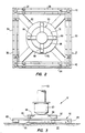
- baseplate assembly 12 is seen to comprise generally a central target member 50 confined within a surrounding alignment frame 52 disposed in a plane transverse to the path of travel 53 of mass 20.
- Frame 52 may conveniently be formed of a rectangular array of horizontal rails 54 from which diagonal supports 62 converge to a hollow, central, cylindrical hub 70 forming an aperture 72 adapted to slideably receive target member 50.
- Frame 52 is positioned so that target member 50 is correctly aligned with path of travel 53 and is free to directly contact the earth surface 22.
- baseplate assembly 12 After baseplate assembly 12 is initially lowered to contact earth surface 22 by extension of lift means 24, further extension compresses shock absorbent members 30 and brings the weight of the transport vehicle 10, including apparatus 11, to bear, at least in part, on frame 52.
- lift means 24 function as jacks which either partially or entirely eliminate vehicle wheels 75 as load bearing members, local conditions determining the preferred arrangement.
- baseplate assembly 12 is so designed that target member 50 also makes direct contact with earth surface 22 but may experience little or no initial static loading due to vehicle weight.
- Members 30, preferably capable of exhibiting three dimensional elasticity, are secured to the under surface of lift frame 26 at spaced intervals so as to transmit vertical force evenly to frame 52.
- Resilient pads 85 as for example, coiled springs or other similar elastic media, attached to the under surfaces of rails 54 such as at their corners are adapted to make contact with earth surface 22.
- frame 52 becomes a highly stable, self-adjusting support for positioning and guidance of target member 50 but does not interfere with its free movement.
- this construction permits a reduced cross-sectional area for target member 50 relative to that of frame 52, thus increasing the dynamic loading on target member 50 per unit area for an impact of any given magnitude.
- target member 50 may easily be made thicker for greater strength.
- frame 52 may be given a wide variety of different structural forms extending laterally between peripheral pads 85 and the position of aperture 72, depending upon considerations such as space, weight, and vehicle under carriage conformation.
- aperture 72 may be formed as an upwardly tapered cone shaped cavity and the tapered external surface 86 of target member 50 may be given a corresponding shape. This enables target member 50 to shift position rotationally within aperture 72. Also, because of its cone shaped interface with hub 70, a downward shift of target member 50 relative to frame 52 permits it to assume a slight sidewise tilt. Both of these types of motion enable target member 50 to better follow and make firm contact with an irregular rocky surface 22. This in turn improves the efficiency of energy coupling and improves the band width of the resultant seismic wave.
- target member 50 is also provided with means such as a plurality of radially extending arms 88 which lie above and are connected to hub 70 through elastic supports such as relatively low spring constant compression springs 90 extending parallel to path 53.
- spring supports 90 also serve as a convenient means for picking up baseplate 50 together with frame 52 when apparatus 11 is moved from one location to another. If the spring constant of springs 90 is made significantly lower than that of the earth itself at the point of contact, no appreciable energy will be transferred secondarily to the earth through frame 52 and pads 85 in the frequency range of interest so as to contaminate the primary seismic pulse.
- target member When frame 52 is statically loaded by vehicle 10, target member should be arranged so that it projects at least to the bottom of aperture 72 and makes contact with earth surface 22. A portion of target member 50 preferably projects beneath the bottom of aperture 72 to a distance somewhat less in height than the unstressed height of pads 85. In this way, the weight of the vehicle may be substantially absorbed in pads 85 under load so that target member 50 sees a relatively small or no initial static load. This in turn may facilitate the ability of target member 50 to make good contact with irregular rock surfaces when impacted.
- FIG. 6 an alternate form of the invention illustrates detail of target member 100 having a right cylindrical profile working slideably within a correspondingly shaped aperture 102 centrally located with respect to an alignment frame 104.
- Target member 100 may be connected to frame 104 through springs 106 extending downwardly to frame 102 from transverse radial projections 108.
- Target member 100 is to be impacted in a manner similar to that described for target member 50, the only difference being that the construction of target member 100 sacrifices some versatility of motion in return for lower construction costs.
- Target member 100 may be given a lower, enlarged diameter flange portion 110 which seats positively against the under surface of guide frame 104 responsive to the restorative forces of springs 106.
- means other than aperture 72 may be devised by those skilled in this art in order to effect a slidable relationship between components functionally analogous to target member 50 and guide frame 52.
- these two components should be relatively arranged so that each is adapted to make direct contact with the earth independent of the other responsive to sufficient extension of lift means 24.
- frame 52 addition strictlyally provides stability and support for the entire apparatus without dictating the lateral extent or static load bearing requirements of the target member.
Landscapes
- Engineering & Computer Science (AREA)
- Remote Sensing (AREA)
- Physics & Mathematics (AREA)
- Life Sciences & Earth Sciences (AREA)
- Acoustics & Sound (AREA)
- Environmental & Geological Engineering (AREA)
- Geology (AREA)
- General Life Sciences & Earth Sciences (AREA)
- General Physics & Mathematics (AREA)
- Geophysics (AREA)
- Geophysics And Detection Of Objects (AREA)
- Vibration Prevention Devices (AREA)
Applications Claiming Priority (2)
| Application Number | Priority Date | Filing Date | Title |
|---|---|---|---|
| US07/020,415 US4804062A (en) | 1987-03-02 | 1987-03-02 | Baseplate assembly for seismic wave generator |
| US20415 | 1987-03-02 |
Publications (2)
| Publication Number | Publication Date |
|---|---|
| EP0281253A2 true EP0281253A2 (fr) | 1988-09-07 |
| EP0281253A3 EP0281253A3 (fr) | 1989-11-29 |
Family
ID=21798507
Family Applications (1)
| Application Number | Title | Priority Date | Filing Date |
|---|---|---|---|
| EP88300939A Withdrawn EP0281253A3 (fr) | 1987-03-02 | 1988-02-04 | Plaque de base pour un générateur d'ondes sismiques |
Country Status (4)
| Country | Link |
|---|---|
| US (1) | US4804062A (fr) |
| EP (1) | EP0281253A3 (fr) |
| AU (1) | AU1193888A (fr) |
| CA (1) | CA1294358C (fr) |
Cited By (1)
| Publication number | Priority date | Publication date | Assignee | Title |
|---|---|---|---|---|
| FR2867863A1 (fr) * | 2004-03-18 | 2005-09-23 | Sercel Rech Const Elect | Dispositif pour emetteur des ondes de vibrations sismiques |
Families Citing this family (5)
| Publication number | Priority date | Publication date | Assignee | Title |
|---|---|---|---|---|
| DE102004014722B3 (de) * | 2004-03-25 | 2005-12-29 | Geoforschungszentrum Potsdam | Seismische Quelle und Verfahren zur Erzeugung seismischer Schwingungen |
| EP2425277B1 (fr) * | 2009-05-01 | 2021-02-17 | INOVA Ltd. | Vibrateur sismique commandé par détection directe du mouvement de la semelle |
| US8342288B2 (en) | 2010-02-18 | 2013-01-01 | Conocophillips Company | Seismic transducers having reduced surface area baseplates and methods of use |
| US8689930B2 (en) * | 2012-03-29 | 2014-04-08 | Westerngeco L.L.C. | Seismic vibrator having airwave suppression |
| CN112557166B (zh) * | 2020-11-19 | 2023-05-16 | 山东科技大学 | 一种加载缓冲装置及用于断层模拟的试验系统和方法 |
Family Cites Families (12)
| Publication number | Priority date | Publication date | Assignee | Title |
|---|---|---|---|---|
| US2620766A (en) * | 1950-03-20 | 1952-12-09 | Sonic Res Corp | Generation and transmission of sound pulses |
| US3106982A (en) * | 1960-05-09 | 1963-10-15 | Texas Instruments Inc | Method and apparatus for creating a seismic source |
| US4056164A (en) * | 1976-07-21 | 1977-11-01 | Western Geophysical Co. | Stabilized portable seismic signal transducer |
| MX151343A (es) * | 1979-08-08 | 1984-11-12 | Conoco Inc | Mejoras en transductor de frecuencia para generar ondas sismicas |
| GB2067289B (en) * | 1979-12-21 | 1984-04-04 | Atlantic Richfield Co | Seismic pulse generator |
| US4284165A (en) * | 1979-12-28 | 1981-08-18 | Atlantic Richfield Company | Acoustic pulse generator |
| US4284164A (en) * | 1979-12-21 | 1981-08-18 | Atlantic Richfield Company | Acoustic pulse generator |
| US4418786A (en) * | 1980-09-18 | 1983-12-06 | Mapco, Inc. | Bottom diaphragm for transporter for a seismic energy source |
| US4402381A (en) * | 1980-12-24 | 1983-09-06 | Atlantic Richfield Company | Vehicle mounting and deployment arrangement for seismic source |
| US4484657A (en) * | 1981-10-13 | 1984-11-27 | Atlantic Richfield Company | Acoustic pulse generator |
| US4660674A (en) * | 1984-11-30 | 1987-04-28 | Atlantic Richfield Company | Mounting and control means for full waveform seismic source |
| US4721181A (en) * | 1986-03-31 | 1988-01-26 | Atlantic Richfield Co. | Base plate locator for seismic source |
-
1987
- 1987-03-02 US US07/020,415 patent/US4804062A/en not_active Expired - Lifetime
-
1988
- 1988-02-04 EP EP88300939A patent/EP0281253A3/fr not_active Withdrawn
- 1988-02-15 CA CA000558868A patent/CA1294358C/fr not_active Expired - Lifetime
- 1988-02-18 AU AU11938/88A patent/AU1193888A/en not_active Abandoned
Cited By (3)
| Publication number | Priority date | Publication date | Assignee | Title |
|---|---|---|---|---|
| FR2867863A1 (fr) * | 2004-03-18 | 2005-09-23 | Sercel Rech Const Elect | Dispositif pour emetteur des ondes de vibrations sismiques |
| WO2005091016A1 (fr) * | 2004-03-18 | 2005-09-29 | Sercel | Dispositif pour emettre des ondes de vibrations sismiques |
| US7499378B2 (en) | 2004-03-18 | 2009-03-03 | Sercel | Device for emitting seismic vibration waves |
Also Published As
| Publication number | Publication date |
|---|---|
| AU1193888A (en) | 1988-09-01 |
| US4804062A (en) | 1989-02-14 |
| EP0281253A3 (fr) | 1989-11-29 |
| CA1294358C (fr) | 1992-01-14 |
Similar Documents
| Publication | Publication Date | Title |
|---|---|---|
| CA1240783A (fr) | Methode et dispositif de generation d'ondes de cisaillement et d'ondes de compression pour l'exploration sismique du sous-sol | |
| EP4226190B1 (fr) | Source sismique pour l'étude sismique mobile | |
| US5980162A (en) | Seismic shock absorbing pier | |
| US4804062A (en) | Baseplate assembly for seismic wave generator | |
| US20070205042A1 (en) | Apparatus and method for generating a seismic signal | |
| EP0024116A2 (fr) | Dispositif mobile avec vibreur à hautes fréquences | |
| US3367443A (en) | Method and apparatus for improving seismic impact signals | |
| JPH0435720B2 (fr) | ||
| US4721181A (en) | Base plate locator for seismic source | |
| US4980874A (en) | Method and apparatus for maximizing seismic shear wave production | |
| US4244437A (en) | Apparatus for generating waves in the ground | |
| EP0278152B1 (fr) | Générateur d'ondes transversales omnidirectionnel muni d'un tube télescopique | |
| US4316521A (en) | Pivoted elevator mounting for mobile land seismic energy source | |
| JPS5938676A (ja) | 地中に剪断音波を発生する装置 | |
| US4967870A (en) | Alignment restoration means for use in seismic apparatus | |
| US4771858A (en) | Shear wave vibrator vehicle isolation system | |
| US3283844A (en) | Seismic prospecting system | |
| EP0368440A2 (fr) | Source sismique vibratoire | |
| JP4098191B2 (ja) | 杭の急速載荷試験装置 | |
| CN216310292U (zh) | 一种工程地球物理勘探装置 | |
| US3405780A (en) | Carrier and positioning mechanism for a seismic energy source | |
| RU2351956C2 (ru) | Устройство для посылки сейсмовибрационных волн | |
| CN116537706A (zh) | 一种矿产地质勘查用勘查装置 | |
| US4850451A (en) | Device for generating in the ground both transverse and longitudinal acoustic waves in a plurality of different directions | |
| CN217501725U (zh) | 一种地质勘探用防塌设备 |
Legal Events
| Date | Code | Title | Description |
|---|---|---|---|
| PUAI | Public reference made under article 153(3) epc to a published international application that has entered the european phase |
Free format text: ORIGINAL CODE: 0009012 |
|
| AK | Designated contracting states |
Kind code of ref document: A2 Designated state(s): DE FR GB |
|
| PUAL | Search report despatched |
Free format text: ORIGINAL CODE: 0009013 |
|
| AK | Designated contracting states |
Kind code of ref document: A3 Designated state(s): DE FR GB |
|
| STAA | Information on the status of an ep patent application or granted ep patent |
Free format text: STATUS: THE APPLICATION IS DEEMED TO BE WITHDRAWN |
|
| 18D | Application deemed to be withdrawn |
Effective date: 19900530 |