EP0281259A2 - Kernreaktoranlage - Google Patents
Kernreaktoranlage Download PDFInfo
- Publication number
- EP0281259A2 EP0281259A2 EP88301027A EP88301027A EP0281259A2 EP 0281259 A2 EP0281259 A2 EP 0281259A2 EP 88301027 A EP88301027 A EP 88301027A EP 88301027 A EP88301027 A EP 88301027A EP 0281259 A2 EP0281259 A2 EP 0281259A2
- Authority
- EP
- European Patent Office
- Prior art keywords
- liquid metal
- nuclear reactor
- reactor plant
- plant
- temperature fluctuations
- Prior art date
- Legal status (The legal status is an assumption and is not a legal conclusion. Google has not performed a legal analysis and makes no representation as to the accuracy of the status listed.)
- Withdrawn
Links
- 238000009434 installation Methods 0.000 title 1
- 229910001338 liquidmetal Inorganic materials 0.000 claims abstract description 35
- 239000000446 fuel Substances 0.000 claims description 14
- 238000000429 assembly Methods 0.000 claims description 10
- 239000007788 liquid Substances 0.000 claims description 5
- 238000009413 insulation Methods 0.000 claims description 2
- 230000000694 effects Effects 0.000 abstract description 2
- 239000002826 coolant Substances 0.000 description 14
- 239000000463 material Substances 0.000 description 10
- DGAQECJNVWCQMB-PUAWFVPOSA-M Ilexoside XXIX Chemical compound C[C@@H]1CC[C@@]2(CC[C@@]3(C(=CC[C@H]4[C@]3(CC[C@@H]5[C@@]4(CC[C@@H](C5(C)C)OS(=O)(=O)[O-])C)C)[C@@H]2[C@]1(C)O)C)C(=O)O[C@H]6[C@@H]([C@H]([C@@H]([C@H](O6)CO)O)O)O.[Na+] DGAQECJNVWCQMB-PUAWFVPOSA-M 0.000 description 6
- 229910052708 sodium Inorganic materials 0.000 description 6
- 239000011734 sodium Substances 0.000 description 6
- 230000004992 fission Effects 0.000 description 2
- 239000012530 fluid Substances 0.000 description 2
- 230000002093 peripheral effect Effects 0.000 description 2
- 230000015572 biosynthetic process Effects 0.000 description 1
- 238000005336 cracking Methods 0.000 description 1
- 238000004519 manufacturing process Methods 0.000 description 1
- 238000000034 method Methods 0.000 description 1
Images
Classifications
-
- G—PHYSICS
- G21—NUCLEAR PHYSICS; NUCLEAR ENGINEERING
- G21C—NUCLEAR REACTORS
- G21C11/00—Shielding structurally associated with the reactor
- G21C11/08—Thermal shields; Thermal linings, i.e. for dissipating heat from gamma radiation which would otherwise heat an outer biological shield ; Thermal insulation
- G21C11/088—Thermal shields; Thermal linings, i.e. for dissipating heat from gamma radiation which would otherwise heat an outer biological shield ; Thermal insulation consisting of a stagnant or a circulating fluid
-
- G—PHYSICS
- G21—NUCLEAR PHYSICS; NUCLEAR ENGINEERING
- G21C—NUCLEAR REACTORS
- G21C15/00—Cooling arrangements within the pressure vessel containing the core; Selection of specific coolants
- G21C15/02—Arrangements or disposition of passages in which heat is transferred to the coolant; Coolant flow control devices
- G21C15/10—Arrangements or disposition of passages in which heat is transferred to the coolant; Coolant flow control devices from reflector or thermal shield
-
- Y—GENERAL TAGGING OF NEW TECHNOLOGICAL DEVELOPMENTS; GENERAL TAGGING OF CROSS-SECTIONAL TECHNOLOGIES SPANNING OVER SEVERAL SECTIONS OF THE IPC; TECHNICAL SUBJECTS COVERED BY FORMER USPC CROSS-REFERENCE ART COLLECTIONS [XRACs] AND DIGESTS
- Y02—TECHNOLOGIES OR APPLICATIONS FOR MITIGATION OR ADAPTATION AGAINST CLIMATE CHANGE
- Y02E—REDUCTION OF GREENHOUSE GAS [GHG] EMISSIONS, RELATED TO ENERGY GENERATION, TRANSMISSION OR DISTRIBUTION
- Y02E30/00—Energy generation of nuclear origin
- Y02E30/30—Nuclear fission reactors
Definitions
- This invention relates to liquid metal cooled fast neutron nuclear reactor plant.
- thermal striping conditions consisting of rapid temperature fluctuations of significant amplitudes, may occur in the liquid metal flow and this can give rise to difficulties if such temperature fields arise in close proximity to component structures.
- the fuel assembly comprises a multiplicity of slender fuel elements or pins over which liquid metal coolant such as sodium flows.
- the fuel assembly is divided into a plurality of sub-assemblies, each comprising a plurality of fuel pins enclosed by a tubular wrapper and having a lifting head.
- the sub-assemblies are positioned in side-by-side array and each one is located in cantilever manner by a lower end spike which is plugged into a fuel assembly supporting structure.
- the sub-assemblies in the central region of the fuel assembly mainly comprise fissile material whilst the sub-assemblies in the surrounding outer region comprise breeder material.
- the fertile material captures neutrons emitted by fission in the fissile material to produce further fissile material.
- fission of some of the newly formed fissile material takes place so that the power output of the breeder sub-assemblies and, therefore, the coolant temperature, progressively increases.
- Varying temperatures of coolant streams flowing from the fuel assembly give rise to the condition known in the fast reactor art as thermal striping, a condition describing the production of rapid temperature fluctuations which can give rise to a risk of cracking in reactor structure material.
- liquid metal cooled fast neutron nuclear reactor plant comprising a vessel containing flowing liquid metal and at least one component or structure having a surface which is immersed in the liquid metal and is vulnerable to flowing liquid metal temperature fluctuations, characterised in that said surface is provided with means for trapping, at least temporarily, a thin layer of liquid metal at said surface to insulate said surface from direct exposure to said temperature fluctuations.
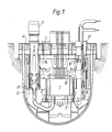
- the invention is particularly applicable to surfaces of components and structures disposed within the reactor primary vessel adjacent the upper, outlet ends of the fuel sub-assemblies forming the reactor core.
- structures and components which are particularly vulnerable are the peripheral shroud tubes of the above-core structure, the instrument rotor and the charge machine.
- the liquid metal trapping means conveniently comprises a cavity or cavities which may be formed by a number of fins projecting from the surface so as to define between each pair of fins a cavity which is exposed to the liquid metal flow and can thereby admit a quantity of the liquid metal (usually sodium) to produce a substantially stagnant volume of liquid metal or at least retain the liquid metal for a sufficient residence time to act as a thermal insulation layer.
- a quantity of the liquid metal usually sodium
- the fins may range from 3 to 5mm in height and the inter fin spacing may be 3 to 5mm.
- the fin thickness may be of the order of 1mm.
- the fuel assembly 1 comprises a central region having sub-assemblies 9A containing fissile or driver material and an outer annular region having sub-assemblies 9B containing fertile or breeder material.
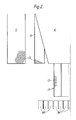
- Figure 2 illustrates a number of zones 12 (shown cross-hatched) which are under sodium and are particularly vulnerable tothese zones 12 being on the peripheral shroud tubes 13 of the above-core structure 10, the charge machine 14 and instrumentation rotor 11.
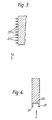
- the surfaces are provided with a series of generally parallel fins which serve to trap a layer of relatively stagnant liquid metal coolant in the spaces between the fins.
- the coolant flow (see arrow A) is generally parallel to the vulnerable surface
- the latter is provided with a series of generally parallel fins 20 substantially perpendicular to the surface and also the coolant flow and forming cavities 22 into which the coolant enters at least for a certain residence time thereby forming a thin layer of coolant across the surface to attenuate the effects of thermal striping.
- Figure 4 illustrates application of the invention to surfaces presented by leading edges of structures or components, ie upon which the coolant flow impinges directly.
- the leading edge is provided with fins 24 to define a cavity 26 serving to trap part of the coolant and thereby create a substantially stagnant layer of coolant.
- the invention has application to components within the reactor primary vessel, it is also applicable to other components of the reactor plant such as heat exchangers.
Landscapes
- Engineering & Computer Science (AREA)
- Physics & Mathematics (AREA)
- Plasma & Fusion (AREA)
- General Engineering & Computer Science (AREA)
- High Energy & Nuclear Physics (AREA)
- Life Sciences & Earth Sciences (AREA)
- Health & Medical Sciences (AREA)
- Biomedical Technology (AREA)
- General Health & Medical Sciences (AREA)
- Molecular Biology (AREA)
- Structure Of Emergency Protection For Nuclear Reactors (AREA)
- Physical Or Chemical Processes And Apparatus (AREA)
- Radiation-Therapy Devices (AREA)
- Monitoring And Testing Of Nuclear Reactors (AREA)
Applications Claiming Priority (2)
| Application Number | Priority Date | Filing Date | Title |
|---|---|---|---|
| GB878704872A GB8704872D0 (en) | 1987-03-02 | 1987-03-02 | Nuclear reactors |
| GB8704872 | 1987-03-02 |
Publications (2)
| Publication Number | Publication Date |
|---|---|
| EP0281259A2 true EP0281259A2 (de) | 1988-09-07 |
| EP0281259A3 EP0281259A3 (de) | 1989-08-16 |
Family
ID=10613196
Family Applications (1)
| Application Number | Title | Priority Date | Filing Date |
|---|---|---|---|
| EP88301027A Withdrawn EP0281259A3 (de) | 1987-03-02 | 1988-02-08 | Kernreaktoranlage |
Country Status (4)
| Country | Link |
|---|---|
| US (1) | US4973444A (de) |
| EP (1) | EP0281259A3 (de) |
| JP (1) | JPS63231295A (de) |
| GB (1) | GB8704872D0 (de) |
Cited By (1)
| Publication number | Priority date | Publication date | Assignee | Title |
|---|---|---|---|---|
| CN109473194A (zh) * | 2018-11-12 | 2019-03-15 | 中国原子能科学研究院 | 一种用于深水池式低温供热堆的衰减筒 |
Families Citing this family (2)
| Publication number | Priority date | Publication date | Assignee | Title |
|---|---|---|---|---|
| RU2608596C1 (ru) * | 2015-10-06 | 2017-01-23 | Акционерное общество "Опытное Конструкторское Бюро Машиностроения имени И.И. Африкантова" (АО "ОКБМ Африкантов") | Ядерный реактор на быстрых нейтронах с жидкометаллическим теплоносителем |
| CN114963826B (zh) * | 2022-05-23 | 2024-05-07 | 西安交通大学 | 一种冷冻靶及用于冷冻靶冰层制备实验的微翅片热容装置 |
Family Cites Families (22)
| Publication number | Priority date | Publication date | Assignee | Title |
|---|---|---|---|---|
| GB387828A (en) * | 1932-01-20 | 1933-02-16 | G N Haden & Sons Ltd | Improvements in methods and apparatus for the emission and absorption of heat radiation |
| BE573083A (de) * | 1957-11-18 | |||
| GB1302861A (de) * | 1969-02-20 | 1973-01-10 | ||
| FR2195822B1 (de) * | 1972-08-08 | 1976-03-12 | Commissariat Energie Atomique | |
| DE2255699A1 (de) * | 1972-11-14 | 1974-05-16 | Kernforschung Gmbh Ges Fuer | Brennelement fuer einen reaktor |
| GB1448994A (en) * | 1973-12-06 | 1976-09-08 | Atomic Energy Authority Uk | Liquid metal cooled fast breeder nuclear reactors |
| FR2260743B1 (de) * | 1974-02-08 | 1978-03-10 | Commissariat Energie Atomique | |
| DE2423501B2 (de) * | 1974-05-15 | 1976-07-29 | Kraftwerk Union AG, 4330 Mülheim | Brennelement fuer gasgekuehlte kernreaktoren |
| FR2284170A1 (fr) * | 1974-09-03 | 1976-04-02 | Commissariat Energie Atomique | Structure de reduction des courants de convection a l'interieur de la cuve d'un reacteur nucleaire |
| GB1527372A (en) * | 1975-07-07 | 1978-10-04 | Atomic Energy Authority Uk | Liquid metal cooled nuclear reactors |
| GB1546331A (en) * | 1977-02-04 | 1979-05-23 | Nuclear Power Co Ltd | Liquid metal cooled fast breeder nuclear reactors |
| GB1568027A (en) * | 1978-01-27 | 1980-05-21 | Nuclear Power Co Ltd | Liquid metal cooled fast breeder nuclear reactors |
| US4303474A (en) * | 1977-03-01 | 1981-12-01 | General Atomic Company | Nuclear reactor core assembly |
| JPS54145897A (en) * | 1978-05-09 | 1979-11-14 | Toshiba Corp | Dipped plate for fast breeder |
| FR2458131A1 (fr) * | 1979-05-31 | 1980-12-26 | Commissariat Energie Atomique | Echangeur intermediaire de chaleur pour reacteur nucleaire |
| FR2532629B1 (fr) * | 1982-09-08 | 1985-12-20 | Stein Industrie | Dispositif de reduction des contraintes thermiques dans la paroi d'un appareil partiellement rempli de liquide et procede de constitution de ce dispositif |
| JPS5960391A (ja) * | 1982-09-30 | 1984-04-06 | 株式会社東芝 | 炉容器の保護断熱装置 |
| JPS5990080A (ja) * | 1982-11-12 | 1984-05-24 | 三菱重工業株式会社 | 液体金属冷却型高速増殖炉の炉内上部構造 |
| JPS59168392A (ja) * | 1983-03-16 | 1984-09-22 | 財団法人 電力中央研究所 | タンク型高速増殖炉 |
| US4761261A (en) * | 1984-02-21 | 1988-08-02 | Stone & Webster Engineering Corp. | Nuclear reactor |
| JPS60233595A (ja) * | 1984-05-02 | 1985-11-20 | 財団法人電力中央研究所 | 高速増殖炉 |
| FR2588411B1 (fr) * | 1985-10-03 | 1987-11-20 | Commissariat Energie Atomique | Reacteur nucleaire a neutrons rapides comportant un bouchon couvercle-coeur perfectionne |
-
1987
- 1987-03-02 GB GB878704872A patent/GB8704872D0/en active Pending
-
1988
- 1988-02-08 EP EP88301027A patent/EP0281259A3/de not_active Withdrawn
- 1988-02-09 US US07/154,009 patent/US4973444A/en not_active Expired - Fee Related
- 1988-02-26 JP JP63044061A patent/JPS63231295A/ja active Pending
Cited By (2)
| Publication number | Priority date | Publication date | Assignee | Title |
|---|---|---|---|---|
| CN109473194A (zh) * | 2018-11-12 | 2019-03-15 | 中国原子能科学研究院 | 一种用于深水池式低温供热堆的衰减筒 |
| CN109473194B (zh) * | 2018-11-12 | 2024-05-14 | 中国原子能科学研究院 | 一种用于深水池式低温供热堆的衰减筒 |
Also Published As
| Publication number | Publication date |
|---|---|
| JPS63231295A (ja) | 1988-09-27 |
| EP0281259A3 (de) | 1989-08-16 |
| US4973444A (en) | 1990-11-27 |
| GB8704872D0 (en) | 1987-04-08 |
Similar Documents
| Publication | Publication Date | Title |
|---|---|---|
| EP0240894B1 (de) | "Water rod" für Siedewasserreaktoren | |
| KR950001734B1 (ko) | 내식성 그리드를 구비한 연료집합체 | |
| US4096033A (en) | Core for a nuclear reactor | |
| US4111747A (en) | Packed rod neutron shield for fast nuclear reactors | |
| US5278883A (en) | Low pressure drop spacer for nuclear fuel assemblies | |
| US4999153A (en) | Flow tripper in combination with spacer deflector | |
| US4309252A (en) | Nuclear reactor constructions | |
| US4235669A (en) | Nuclear reactor composite fuel assembly | |
| US4728490A (en) | Fuel rod spacer with perimeter scoops for diverting liquid coolant flow | |
| KR910003801B1 (ko) | 블랭킷 어셈블리 | |
| US5272741A (en) | Nuclear fuel assembly | |
| KR970004351B1 (ko) | 비등수형 원자로의 연료집합체 | |
| US3574058A (en) | Nuclear fuel assembly | |
| KR930008243B1 (ko) | 비등수형 원자로용 제어봉 | |
| US4759912A (en) | BWR fuel assembly having hybrid fuel design | |
| US4973444A (en) | Nuclear reactor installations | |
| KR970004417B1 (ko) | 연료봉 소다발 | |
| US20040005025A1 (en) | Spacer grid with double deflected vanes for nuclear fuel assemblies | |
| US5493590A (en) | Critical power enhancement system for a pressurized fuel channel type nuclear reactor using CHF enhancement appendages | |
| US3798125A (en) | Nuclear fuel subassembly | |
| US4154651A (en) | Liquid metal cooled fast breeder nuclear reactors | |
| US3227621A (en) | Heterogeneous atomic reactor | |
| JP2510006B2 (ja) | 沸騰水型原子炉用の燃料バンドル | |
| JP2531910B2 (ja) | 沸騰水型原子炉内の寄生バイパス流を減少する装置 | |
| JPS6247115Y2 (de) |
Legal Events
| Date | Code | Title | Description |
|---|---|---|---|
| PUAI | Public reference made under article 153(3) epc to a published international application that has entered the european phase |
Free format text: ORIGINAL CODE: 0009012 |
|
| AK | Designated contracting states |
Kind code of ref document: A2 Designated state(s): BE DE FR GB IT |
|
| PUAL | Search report despatched |
Free format text: ORIGINAL CODE: 0009013 |
|
| RHK1 | Main classification (correction) |
Ipc: G21C 11/08 |
|
| AK | Designated contracting states |
Kind code of ref document: A3 Designated state(s): BE DE FR GB IT |
|
| 17P | Request for examination filed |
Effective date: 19890928 |
|
| STAA | Information on the status of an ep patent application or granted ep patent |
Free format text: STATUS: THE APPLICATION IS DEEMED TO BE WITHDRAWN |
|
| 18D | Application deemed to be withdrawn |
Effective date: 19910829 |