EP0281277A2 - Logement de clé - Google Patents
Logement de clé Download PDFInfo
- Publication number
- EP0281277A2 EP0281277A2 EP88301352A EP88301352A EP0281277A2 EP 0281277 A2 EP0281277 A2 EP 0281277A2 EP 88301352 A EP88301352 A EP 88301352A EP 88301352 A EP88301352 A EP 88301352A EP 0281277 A2 EP0281277 A2 EP 0281277A2
- Authority
- EP
- European Patent Office
- Prior art keywords
- receptacle
- key
- contact
- contact pins
- electrical
- Prior art date
- Legal status (The legal status is an assumption and is not a legal conclusion. Google has not performed a legal analysis and makes no representation as to the accuracy of the status listed.)
- Granted
Links
Images


Classifications
-
- G—PHYSICS
- G07—CHECKING-DEVICES
- G07C—TIME OR ATTENDANCE REGISTERS; REGISTERING OR INDICATING THE WORKING OF MACHINES; GENERATING RANDOM NUMBERS; VOTING OR LOTTERY APPARATUS; ARRANGEMENTS, SYSTEMS OR APPARATUS FOR CHECKING NOT PROVIDED FOR ELSEWHERE
- G07C9/00—Individual registration on entry or exit
- G07C9/00174—Electronically operated locks; Circuits therefor; Nonmechanical keys therefor, e.g. passive or active electrical keys or other data carriers without mechanical keys
- G07C9/00944—Details of construction or manufacture
Definitions
- This invention relates to improvements in the functional design of electrical receptacles for use in combination with electrical key-like devices.
- the invention is an improvement over U.S. Patent 4,620,088, issued October 28, 1986, entitled “Receptacle Design for use with Electronic Key-Like Device”; U.S. Patent 4,297,569, issued October 27, 1981, entitled “Microelectronic Memory with Receptacle and Systems Therefor”; and U.S. Patent 4,326,125, issued April 20, 1982, entitled “Improved Microelectronic Memory Key with Receptacle and Systems Therefor” all of which are incorporated herein by reference.
- the referenced prior art discloses electrical key-like devices in which a master circuit or electrical operating system of some kind, such as a computer system, is activated by use of a portable key-like device which is combined with the electrical system, as by insertion into a suitable receptacle or the like, to make electrical contact or connection with the system.
- This invention is concerned broadly with such portable devices and with their use in such systems.
- This invention relates to an improved design for the receptacle of such systems which lessens the number of manufacturing steps required for assembly, as well as eliminating a number of components to provide substantial cost savings in mass production.
- this invention concerns an improved receptacle for receiving electrical key-like devices and providing electrical connection between such devices and a computer or other master circuit operating system.
- the key-like devices of the referenced prior art and of this patent application retain relatively large amounts of data bits (information) in a portable medium of small size.
- Very fast data access and data transfer rates are provided by electrical connection of such devices to a master electrical circuit means which includes a program memory and a processor, through insertion of the key-like device into a specially designed electrical receptacle. It is desirable that the receptacle have a design which provides good electrical contact with the computer, even after prolonged usage or tampering.
- the electrical contacts in the receptacle be protected from casual damage when the receptacle is not in use, as well as protecting the contact pins from the deliberately inflicted damage and improper usage. It is also desirable to provide an improved receptacle design such that the receptacle may be soldered directly onto a printed circuit board. It is an aim of this invention to fulfill these and other objectives which will be become apparant hereinbelow.
- microelectronic data keys described therein are not only concerned with the storage of data (information) and its introduction into a computer or other electrical circuit, but also with the portability of microelectronic circuit chips or dies, whether the purpose of the electrical circuit system into which and key is introduced is the storage of information or any other purpose, such as a control function.
- the various circuit elements which may be embedded in the key are packaged in a sturdy configuration for insertion into a receptacle.
- the receptacle is connected to an access device or the like for a variety of purposes. Any circuit means which can be so packaged and which can augment any other existing circuit contained in a master operating system or the like is usable in such keys.
- the key-like devices are specifically designed for insertion into an electrical receptacle and rotation therein to establish contact through the receptacle to the master electrical system.
- the present invention specifically relates to improvements in the design of such receptacles, lessening the number of steps required in the manufacture of the receptacle, and eliminating some of the components previously required.
- the present invention also allows for the receptacle to be soldered directly to a printed circuit board, eliminating the previously required connective components as well as allowing the receptacle to be fitted into smaller areas. For example, it may then be fitted onto an expansion board in a digital computer, including personal computers, or to other circuit boards, particularly those designed to fit in small areas.
- Key 10 comprises nonconductive head and insert body portions 11 and 12 respectively.
- the insert body portion 12 contains a circuit element, such as an integrated circuit or microelectronic chip embedded therein (not shown).
- Leads 16 of the circuit element extend therefrom through the body portion of the key to the upper and lower surfaces thereof where they lie exposed within spaced contact grooves 18 to form electrical contact areas on the key.
- Body 12 also includes an external registration rib 19 to assure correct orientation of the key for insertion into the receptacle generally indicated at 20.
- receptacle 20 comprises a contact support member 22, an end wall member 24 attached to contact support member 22 and a cylindrical-like enclosure member 26.
- End wall member 24 contains a latch tab member 28.
- Enclosure member 26 contains a latch tab 27 which is designed to snap fit over latch member 28 when enclosure member 26 is mounted on and attached to contact support member 22.
- End wall member 24 also contains cut-out portions 67 which admit enclosure ends 65, aiding in providing a tightly fit receptacle.
- Enclosure member 26 also contains front flanges 32 which surrounds a keyway opening 34. Front flange 32 includes raised key-stop portions 33 which act to stop the rotation of the key by abutment of the stops against keyhead 11.
- Opening 34 is preferably a compound shape comprising a generally rectangular slot which permits insertion of the key insert portion 12 into the receptacle and a generally circular central expansion area, the diameter of which corresponds generally to the thickness of the key between grooves 36 located adjacent head portion 11 of the key.
- the shape of keyway opening 34 cooperates with grooves 36 so that the key may not be rotated until it is fully inserted into receptacle 20. Additionally, once rotation has begun, the key may not be removed until it is returned to the insertion position.
- receptacle 20 is a multi-part assembly which includes contact support member 22, end wall member 24 integrally attached to contact support member 22, enclosure 26, and guard member 40, all of which are preferably formed of molded plastic.
- contact support 22 is made of polyphenylene sulpide; guard member 40 is made of nylon, and enclosure 20 is made of acetal.
- Contact support 22 also contains a plurality of inwardly and outwardly extending finger-like spring contact pins 50, the inner ends being indicated at 50a, the outer ends being indicated at 50b.
- these pins are made of Paliney® type 6 or 7 metal available from the Ney Company. Stainless steel may also be used.
- the contact support 22 is preferably molded around contact pins 50 as shown.
- Thrust web members 63 are positioned to fit between discoid elements 62 (described below) of guard means 40, preventing the guard means from moving forward or backward along contact support 22 when it is mounted thereon.
- a separated pair of contact pins 51 with inner ends 51a and outer ends 51b are also carried by support 22 in the same way as pins 50.
- Pins 51 serve a switching function (LOFO), as later described, while pins 50 serve to electrically contact a key upon insertion and turning in the receptacle.
- LOFO switching function
- End wall member 24 contains a centered depression 54 on its upper surface in which a latch tab member in the form of an upwardly extending tab 28 is carried.
- the latch member tab is used to snap fit inside the latch opening 56 contained on enclosure 26 in rearwarly extending horizontal tab 27.
- enclosure member 26 may also include tab 87 which snap fits over contact support 22, aiding in providing a tightly fit enclosure 26.
- a contact pin protect sleeve or guard means 40 as shown in Fig. 2 comprises a generally tubular structure of cylindrical shape preferably, although various cross-sectional shaped may be utilized so long as the structure is rotatable within an appropriate shaped chamber of enclosure 26.
- the interior surfaces of enclosure 20 are suitably curved to facilitate rotation of cylindrical guard means 40 therein.
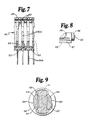
- Figures 3, 7 and 9 should also be referred to in addition to Figure 2 for details concerning the structure of guard means 40. From these Figures, it can be seen that the guard is formed of a plurality of discoid elements 62 concentrically spaced along a common axis and interconnected by two oppositely disposed rows of paired rib elements 64 (best seen in Fig.
- rib elements 64 will have inwardly tapered tops and bottoms 66 and 67 as can be seen in Fig. 9.
- the discoid elements 62 contain aligned openings 68 which, along with the rib-like elements 64, define a keyway into which a key-like device, such as key 10, may be inserted when guard means 40 is carried within the enclosure 25.
- guard means 40 may be mounted on contact support 22 with enclosure member 26 seated in grooves 52 by means of runners 53 to snap fit with latch member 28 thereby forming the assembled electrical receptacle 20.
- the keyway defined by discoid elements 62 and rib elements 64 has an open top and open bottom (best shown in Fig.
- a key registration grooves 59 (best seen in Figs. 2 and 6) is also included in guard means 40.
- the key registration rib 19 included on key 10 fits into key registration groove 59 thereby preventing insertion of the key in a predetermined orientation.
- Head spacers 61 are also included on guard member 40 for key positioning purposes when the guard member is rotated with the key (best seen in Fig. 2).
- the head spacers 61 also serve to increase the torque required to rotate the key to stops 33. Spacers 61 abut matching stops 33a inside enclosure 26 (See Fig. 2).
- stops 70 may be carried on the periphery of discoid elements 62 and an appropriate seat 102 (Fig. 4) may be provided in enclosure 20 to afford a positive snap-action rotation of guard means 40 when rotated inside enclosure member 26.
- stops 70 and seat 102 will be so ar ranged as to position the keyway of guard means 40 in a normally open or upright position, hereinafter termed the "guard" position (shown in Fig. 5), in which the rib elements 64 are positioned along the sides of enclosure member 20 such that contact pins 50 lie between rib elements 64 which separate contact pins 50 from keyway 34, thus preventing their exposure when a key is not inserted into the receptacle.
- guard means 40 rotates with the key to a position, as shown in Figure 6, whereby contacts 16 on the key are able to contact the contact pins 50 through the open top and bottom, which have been respectively rotated to the sides thereof, of the keyway defined by the guard means.
- Guard means 40 also may include detent beak 89 (best seen in Figs. 3 and 5). As the guard means 40 is rotated, detent 89 snaps out of cut-out 91 located on the contact support. This provides an audible "click” to denote the beginning of rotation, while stops 70 provide an audible "click” to denote the end of rotation.
- the receptacle will also preferably include a switch element referred to herein as a last-on-first-off (LOFO) switch, the purpose of which is to render certain that all contact pins 50 are completely contacted by all key contacts 16 before the LOFO switch is closed allowing electrical connection between the key contacts, the receptacle contacts and the operating circuitry.
- the LOFO switch will comprise a pair of contact pins 51 identical to pins 50 disposed at the wall member end of contact support 22 and a shunt in the form of a U-shaped or staple-shaped wire 75 inserted into the last pair of discoid elements 62, as shown in Figure 3, at the distal end of guard means 40. As can be seen in Figs.
- the staple 75 is arranged a few degrees from vertical so as to lag behind the rotational movement of the key contacts 16 when a key is rotated in keyway 34 to engage contact pins 50 in the receptacle. Consequently, contact by legs 76 of shunt member 75 to the oppositely disposed contact pins 51 in the receptacle will lag contact between the key contacts 16 and contact pins 50, making certain that all key/receptacle contacts are positively engaged before legs 76 contact the corresponding receptacle contact pins 51 to complete electrical connection between all contacts and the operating circuit.
- FIG. 4 shows enclosure 20 allowing a view of the inside of the enclosure.
- Latch opening 56 is shown formed at the inner end of enclosure 20 by means of tab 27.
- Runners 53 are constructed to fit into grooves 52 of the contact support member 22.
- the open detent 102, the snap-over area 104 and the free area 106 all interact with stops 70 on guard member 40 to provide an audible click and feel for determining when the key has been turned a sufficient amount.
- Figures 5 and 6 show the positions of the guard member upon insertion and rotation of key 10, respectively.
- Figures 5 and 6 are a rear view of the receptacle with the rear of the enclosure in sillouette so as to enable the viewer to see the interior portions of the receptacle.
- staple 75 with legs 76 comes into contact with contact pins 51 only after the contacts 16 on key 10 have completed contact with all other contact pins 50.
- positioning elements 200 and 204 which may be distributed in various areas on the underside of support 22.
Landscapes
- Engineering & Computer Science (AREA)
- Manufacturing & Machinery (AREA)
- Physics & Mathematics (AREA)
- General Physics & Mathematics (AREA)
- Details Of Connecting Devices For Male And Female Coupling (AREA)
- Cable Accessories (AREA)
- Switches With Compound Operations (AREA)
- Coupling Device And Connection With Printed Circuit (AREA)
Priority Applications (1)
| Application Number | Priority Date | Filing Date | Title |
|---|---|---|---|
| AT88301352T ATE75517T1 (de) | 1987-03-02 | 1988-02-18 | Schluesselaufnahmevorrichtung. |
Applications Claiming Priority (2)
| Application Number | Priority Date | Filing Date | Title |
|---|---|---|---|
| US07/020,745 US4752679A (en) | 1987-03-02 | 1987-03-02 | Receptacle device |
| US20745 | 1987-03-02 |
Publications (3)
| Publication Number | Publication Date |
|---|---|
| EP0281277A2 true EP0281277A2 (fr) | 1988-09-07 |
| EP0281277A3 EP0281277A3 (en) | 1988-10-19 |
| EP0281277B1 EP0281277B1 (fr) | 1992-04-29 |
Family
ID=21800302
Family Applications (1)
| Application Number | Title | Priority Date | Filing Date |
|---|---|---|---|
| EP88301352A Expired - Lifetime EP0281277B1 (fr) | 1987-03-02 | 1988-02-18 | Logement de clé |
Country Status (5)
| Country | Link |
|---|---|
| US (1) | US4752679A (fr) |
| EP (1) | EP0281277B1 (fr) |
| AT (1) | ATE75517T1 (fr) |
| CA (1) | CA1297687C (fr) |
| DE (1) | DE3870488D1 (fr) |
Families Citing this family (19)
| Publication number | Priority date | Publication date | Assignee | Title |
|---|---|---|---|---|
| US5053199A (en) * | 1989-02-21 | 1991-10-01 | Boehringer Mannheim Corporation | Electronically readable information carrier |
| USD345686S (en) | 1992-02-05 | 1994-04-05 | Datakey, Inc. | Electrical information key |
| US5322992A (en) * | 1992-06-22 | 1994-06-21 | Lynx Systems, Inc. | Implement for controlling an electronic lock mechanism |
| US5526662A (en) * | 1993-12-28 | 1996-06-18 | Duncan Industries Parking Control Systems Corp. | Cashless key and receptacle system |
| AU754594B2 (en) | 1998-04-24 | 2002-11-21 | Indigo Medical, Incorporated | Energy application system with ancillary information exchange capability, energy applicator, and methods associated therewith |
| US6661334B1 (en) * | 2000-09-26 | 2003-12-09 | Hewlett-Packard Development Company, L.P. | Methods and apparatus for verifying the installation of components in a system |
| US6932517B2 (en) | 2000-10-27 | 2005-08-23 | Ethicon Endo-Surgery, Inc. | Connector incorporating a contact pad surface on a plane parallel to a longitudinal axis |
| US6358093B1 (en) | 2001-02-07 | 2002-03-19 | Adc Telecommunications, Inc. | Normal through jack and method |
| US7158008B2 (en) * | 2002-03-29 | 2007-01-02 | Datakey Electronincs, Inc. | Electronic key system and method |
| WO2005010830A1 (fr) * | 2003-07-17 | 2005-02-03 | Datakey Electronics, Inc. | Systeme et procede de commande d'acces a cle electronique |
| USD557588S1 (en) | 2006-08-23 | 2007-12-18 | Datakey Electronics, Inc. | Electronic key |
| CN101816010A (zh) * | 2007-07-19 | 2010-08-25 | 数据匙电子有限公司 | Rf令牌和接纳器系统与方法 |
| EP2191412A1 (fr) * | 2007-08-29 | 2010-06-02 | Datakey Electronics, INC. | Système et procédé de support de données |
| USD649894S1 (en) | 2008-12-30 | 2011-12-06 | Atek Products, Llc | Electronic token and data carrier |
| USD649896S1 (en) | 2009-01-30 | 2011-12-06 | Atek Products, Llc | Electronic token and data carrier receptacle |
| WO2010088556A1 (fr) | 2009-01-30 | 2010-08-05 | Datakey Electronics, Inc. | Système de support de données ayant une empreinte compacte et procédés de fabrication de celui-ci |
| USD649895S1 (en) | 2009-01-30 | 2011-12-06 | Atek Products, Llc | Electronic token and data carrier |
| US8610574B2 (en) * | 2009-06-15 | 2013-12-17 | Gerald Isaac Kestenbaum | Item storage and tracking system |
| USD649486S1 (en) | 2009-07-09 | 2011-11-29 | ATEK Products , LLC | Electronic token and data carrier |
Family Cites Families (14)
| Publication number | Priority date | Publication date | Assignee | Title |
|---|---|---|---|---|
| US3001167A (en) * | 1958-02-07 | 1961-09-19 | Plishner | Multi-conductor electrical connector |
| FR1321529A (fr) * | 1962-02-07 | 1963-03-22 | Moreaux & Cie | Système de sécurité pour serrure à fonctionnement automatique |
| SE376200B (fr) * | 1969-04-02 | 1975-05-12 | M Nicola | |
| US3686659A (en) * | 1970-01-05 | 1972-08-22 | Dasy Int Sa | Electronic locking device |
| US3663774A (en) * | 1971-03-04 | 1972-05-16 | Motorola Inc | Key operated switch |
| US3761892A (en) * | 1971-07-19 | 1973-09-25 | R Bosnyak | Electronic locking system |
| US3829833A (en) * | 1972-10-24 | 1974-08-13 | Information Identification Co | Code element identification method and apparatus |
| US3889501A (en) * | 1973-08-14 | 1975-06-17 | Charles P Fort | Combination electrical and mechanical lock system |
| US4297569A (en) * | 1979-06-28 | 1981-10-27 | Datakey, Inc. | Microelectronic memory key with receptacle and systems therefor |
| US4326125A (en) * | 1980-06-26 | 1982-04-20 | Datakey, Inc. | Microelectronic memory key with receptacle and systems therefor |
| US4379966A (en) * | 1981-07-23 | 1983-04-12 | Datakey, Inc. | Receptacle for electronic information key |
| US4420794A (en) * | 1981-09-10 | 1983-12-13 | Research, Incorporated | Integrated circuit switch |
| US4620088A (en) * | 1983-03-02 | 1986-10-28 | Datakey, Inc. | Receptacle design for use with electronic key-like device |
| US4522456A (en) * | 1984-01-25 | 1985-06-11 | Datakey, Inc. | Electronic tag receptacle and reader |
-
1987
- 1987-03-02 US US07/020,745 patent/US4752679A/en not_active Expired - Lifetime
-
1988
- 1988-02-18 AT AT88301352T patent/ATE75517T1/de not_active IP Right Cessation
- 1988-02-18 EP EP88301352A patent/EP0281277B1/fr not_active Expired - Lifetime
- 1988-02-18 DE DE8888301352T patent/DE3870488D1/de not_active Expired - Lifetime
- 1988-02-24 CA CA000559682A patent/CA1297687C/fr not_active Expired - Lifetime
Also Published As
| Publication number | Publication date |
|---|---|
| US4752679A (en) | 1988-06-21 |
| ATE75517T1 (de) | 1992-05-15 |
| EP0281277A3 (en) | 1988-10-19 |
| CA1297687C (fr) | 1992-03-24 |
| DE3870488D1 (de) | 1992-06-04 |
| EP0281277B1 (fr) | 1992-04-29 |
Similar Documents
| Publication | Publication Date | Title |
|---|---|---|
| EP0281277A2 (fr) | Logement de clé | |
| US4659915A (en) | Receptacle design for use with electronic key-like device | |
| US6062901A (en) | Low profile battery holder assembly for printed circuit board | |
| US4620088A (en) | Receptacle design for use with electronic key-like device | |
| US4420794A (en) | Integrated circuit switch | |
| US6276950B1 (en) | Socket for printed circuit board | |
| US6027350A (en) | Ejecting mechanism for card cartridge connector | |
| US5667397A (en) | Smart card connector | |
| US4307927A (en) | Polarization key for electrical connector | |
| JPH0863556A (ja) | 電気スマートカード用ポータブルインターフェース | |
| US6764327B2 (en) | Electrical card connector with end position switch | |
| US6692277B2 (en) | Electrical card connector with spring switch | |
| JP3824147B2 (ja) | カード用コネクタ | |
| US8118607B2 (en) | Electronic card with protecting mechanism for protecting contacts thereof | |
| US6764322B1 (en) | Power plug receptacle having safety cover | |
| US4642734A (en) | Integrated circuit chip switch | |
| JP3368465B2 (ja) | Icカードコネクタ | |
| US20080280487A1 (en) | Card connector | |
| US5902143A (en) | Retainer for use with card | |
| US20090130911A1 (en) | Spindle motor connector and method of making the same | |
| US6145747A (en) | Memory card and card connector and assembly thereof | |
| US6413106B1 (en) | Card connector having ejection mechanism with two ejection drawer plates | |
| JP2005044595A (ja) | Pcカードコネクタ組立体 | |
| JPH01166475A (ja) | メモリカード用コネクタ | |
| US3988555A (en) | Cam operated switch |
Legal Events
| Date | Code | Title | Description |
|---|---|---|---|
| PUAI | Public reference made under article 153(3) epc to a published international application that has entered the european phase |
Free format text: ORIGINAL CODE: 0009012 |
|
| PUAL | Search report despatched |
Free format text: ORIGINAL CODE: 0009013 |
|
| AK | Designated contracting states |
Kind code of ref document: A2 Designated state(s): AT BE CH DE FR GB IT LI NL SE |
|
| AK | Designated contracting states |
Kind code of ref document: A3 Designated state(s): AT BE CH DE FR GB IT LI NL SE |
|
| RHK1 | Main classification (correction) |
Ipc: E05B 49/02 |
|
| 17P | Request for examination filed |
Effective date: 19881122 |
|
| 17Q | First examination report despatched |
Effective date: 19901122 |
|
| GRAA | (expected) grant |
Free format text: ORIGINAL CODE: 0009210 |
|
| AK | Designated contracting states |
Kind code of ref document: B1 Designated state(s): AT BE CH DE FR GB IT LI NL SE |
|
| REF | Corresponds to: |
Ref document number: 75517 Country of ref document: AT Date of ref document: 19920515 Kind code of ref document: T |
|
| REF | Corresponds to: |
Ref document number: 3870488 Country of ref document: DE Date of ref document: 19920604 |
|
| ITF | It: translation for a ep patent filed | ||
| ET | Fr: translation filed | ||
| PLBE | No opposition filed within time limit |
Free format text: ORIGINAL CODE: 0009261 |
|
| STAA | Information on the status of an ep patent application or granted ep patent |
Free format text: STATUS: NO OPPOSITION FILED WITHIN TIME LIMIT |
|
| 26N | No opposition filed | ||
| EAL | Se: european patent in force in sweden |
Ref document number: 88301352.6 |
|
| PGFP | Annual fee paid to national office [announced via postgrant information from national office to epo] |
Ref country code: SE Payment date: 20000207 Year of fee payment: 13 |
|
| PGFP | Annual fee paid to national office [announced via postgrant information from national office to epo] |
Ref country code: CH Payment date: 20010213 Year of fee payment: 14 Ref country code: AT Payment date: 20010213 Year of fee payment: 14 |
|
| PG25 | Lapsed in a contracting state [announced via postgrant information from national office to epo] |
Ref country code: SE Free format text: LAPSE BECAUSE OF NON-PAYMENT OF DUE FEES Effective date: 20010219 |
|
| PGFP | Annual fee paid to national office [announced via postgrant information from national office to epo] |
Ref country code: NL Payment date: 20010228 Year of fee payment: 14 |
|
| PGFP | Annual fee paid to national office [announced via postgrant information from national office to epo] |
Ref country code: BE Payment date: 20010427 Year of fee payment: 14 |
|
| EUG | Se: european patent has lapsed |
Ref document number: 88301352.6 |
|
| REG | Reference to a national code |
Ref country code: GB Ref legal event code: IF02 |
|
| PG25 | Lapsed in a contracting state [announced via postgrant information from national office to epo] |
Ref country code: AT Free format text: LAPSE BECAUSE OF NON-PAYMENT OF DUE FEES Effective date: 20020218 |
|
| PG25 | Lapsed in a contracting state [announced via postgrant information from national office to epo] |
Ref country code: LI Free format text: LAPSE BECAUSE OF NON-PAYMENT OF DUE FEES Effective date: 20020228 Ref country code: BE Free format text: LAPSE BECAUSE OF NON-PAYMENT OF DUE FEES Effective date: 20020228 Ref country code: CH Free format text: LAPSE BECAUSE OF NON-PAYMENT OF DUE FEES Effective date: 20020228 |
|
| BERE | Be: lapsed |
Owner name: DATAKEY INC. Effective date: 20020228 |
|
| PG25 | Lapsed in a contracting state [announced via postgrant information from national office to epo] |
Ref country code: NL Free format text: LAPSE BECAUSE OF NON-PAYMENT OF DUE FEES Effective date: 20020901 |
|
| REG | Reference to a national code |
Ref country code: CH Ref legal event code: PL |
|
| NLV4 | Nl: lapsed or anulled due to non-payment of the annual fee |
Effective date: 20020901 |
|
| PGFP | Annual fee paid to national office [announced via postgrant information from national office to epo] |
Ref country code: GB Payment date: 20070223 Year of fee payment: 20 |
|
| PGFP | Annual fee paid to national office [announced via postgrant information from national office to epo] |
Ref country code: DE Payment date: 20070330 Year of fee payment: 20 |
|
| PGFP | Annual fee paid to national office [announced via postgrant information from national office to epo] |
Ref country code: IT Payment date: 20070526 Year of fee payment: 20 |
|
| REG | Reference to a national code |
Ref country code: GB Ref legal event code: PE20 |
|
| PGFP | Annual fee paid to national office [announced via postgrant information from national office to epo] |
Ref country code: FR Payment date: 20070221 Year of fee payment: 20 |
|
| PG25 | Lapsed in a contracting state [announced via postgrant information from national office to epo] |
Ref country code: GB Free format text: LAPSE BECAUSE OF EXPIRATION OF PROTECTION Effective date: 20080217 |