EP0281294B1 - Flüssigkeitsversorgungssystem mit Kompensation des Flussdefizits - Google Patents
Flüssigkeitsversorgungssystem mit Kompensation des Flussdefizits Download PDFInfo
- Publication number
- EP0281294B1 EP0281294B1 EP88301465A EP88301465A EP0281294B1 EP 0281294 B1 EP0281294 B1 EP 0281294B1 EP 88301465 A EP88301465 A EP 88301465A EP 88301465 A EP88301465 A EP 88301465A EP 0281294 B1 EP0281294 B1 EP 0281294B1
- Authority
- EP
- European Patent Office
- Prior art keywords
- pump
- pressure
- check valve
- period
- motor
- Prior art date
- Legal status (The legal status is an assumption and is not a legal conclusion. Google has not performed a legal analysis and makes no representation as to the accuracy of the status listed.)
- Expired - Lifetime
Links
- 239000012530 fluid Substances 0.000 title claims description 43
- 230000006735 deficit Effects 0.000 title claims description 20
- 239000002904 solvent Substances 0.000 claims description 40
- 208000034423 Delivery Diseases 0.000 claims description 26
- 238000005086 pumping Methods 0.000 claims description 18
- 230000007812 deficiency Effects 0.000 claims description 9
- 230000033228 biological regulation Effects 0.000 claims description 2
- 238000005070 sampling Methods 0.000 claims description 2
- 230000008859 change Effects 0.000 description 8
- 238000004128 high performance liquid chromatography Methods 0.000 description 8
- 230000033001 locomotion Effects 0.000 description 7
- 230000007423 decrease Effects 0.000 description 6
- 239000003990 capacitor Substances 0.000 description 5
- 230000006835 compression Effects 0.000 description 4
- 238000007906 compression Methods 0.000 description 4
- 230000009977 dual effect Effects 0.000 description 4
- 238000000034 method Methods 0.000 description 4
- 230000006837 decompression Effects 0.000 description 3
- 239000007789 gas Substances 0.000 description 3
- 230000010349 pulsation Effects 0.000 description 3
- 230000008878 coupling Effects 0.000 description 2
- 238000010168 coupling process Methods 0.000 description 2
- 238000005859 coupling reaction Methods 0.000 description 2
- 230000001419 dependent effect Effects 0.000 description 2
- 238000012544 monitoring process Methods 0.000 description 2
- 239000000243 solution Substances 0.000 description 2
- SMYMJHWAQXWPDB-UHFFFAOYSA-N (2,4,5-trichlorophenoxy)acetic acid Chemical compound OC(=O)COC1=CC(Cl)=C(Cl)C=C1Cl SMYMJHWAQXWPDB-UHFFFAOYSA-N 0.000 description 1
- 230000009471 action Effects 0.000 description 1
- 230000003213 activating effect Effects 0.000 description 1
- 238000004458 analytical method Methods 0.000 description 1
- 230000000903 blocking effect Effects 0.000 description 1
- 238000004587 chromatography analysis Methods 0.000 description 1
- 238000010276 construction Methods 0.000 description 1
- 230000003247 decreasing effect Effects 0.000 description 1
- 238000010586 diagram Methods 0.000 description 1
- 230000000694 effects Effects 0.000 description 1
- 238000001595 flow curve Methods 0.000 description 1
- 230000000977 initiatory effect Effects 0.000 description 1
- 238000002347 injection Methods 0.000 description 1
- 239000007924 injection Substances 0.000 description 1
- 238000007689 inspection Methods 0.000 description 1
- 230000010354 integration Effects 0.000 description 1
- 239000007788 liquid Substances 0.000 description 1
- 230000014759 maintenance of location Effects 0.000 description 1
- 239000000463 material Substances 0.000 description 1
- 238000005259 measurement Methods 0.000 description 1
- 230000007246 mechanism Effects 0.000 description 1
- 239000002184 metal Substances 0.000 description 1
- 239000000203 mixture Substances 0.000 description 1
- 238000012856 packing Methods 0.000 description 1
- 230000000737 periodic effect Effects 0.000 description 1
- 230000002028 premature Effects 0.000 description 1
- 230000001105 regulatory effect Effects 0.000 description 1
- 230000008439 repair process Effects 0.000 description 1
- 230000000717 retained effect Effects 0.000 description 1
- 238000007493 shaping process Methods 0.000 description 1
- 239000002699 waste material Substances 0.000 description 1
- 238000004804 winding Methods 0.000 description 1
Images



Classifications
-
- G—PHYSICS
- G01—MEASURING; TESTING
- G01N—INVESTIGATING OR ANALYSING MATERIALS BY DETERMINING THEIR CHEMICAL OR PHYSICAL PROPERTIES
- G01N30/00—Investigating or analysing materials by separation into components using adsorption, absorption or similar phenomena or using ion-exchange, e.g. chromatography or field flow fractionation
- G01N30/02—Column chromatography
- G01N30/26—Conditioning of the fluid carrier; Flow patterns
- G01N30/28—Control of physical parameters of the fluid carrier
- G01N30/36—Control of physical parameters of the fluid carrier in high pressure liquid systems
-
- F—MECHANICAL ENGINEERING; LIGHTING; HEATING; WEAPONS; BLASTING
- F04—POSITIVE - DISPLACEMENT MACHINES FOR LIQUIDS; PUMPS FOR LIQUIDS OR ELASTIC FLUIDS
- F04B—POSITIVE-DISPLACEMENT MACHINES FOR LIQUIDS; PUMPS
- F04B49/00—Control, e.g. of pump delivery, or pump pressure of, or safety measures for, machines, pumps, or pumping installations, not otherwise provided for, or of interest apart from, groups F04B1/00 - F04B47/00
- F04B49/22—Control, e.g. of pump delivery, or pump pressure of, or safety measures for, machines, pumps, or pumping installations, not otherwise provided for, or of interest apart from, groups F04B1/00 - F04B47/00 by means of valves
- F04B49/225—Control, e.g. of pump delivery, or pump pressure of, or safety measures for, machines, pumps, or pumping installations, not otherwise provided for, or of interest apart from, groups F04B1/00 - F04B47/00 by means of valves with throttling valves or valves varying the pump inlet opening or the outlet opening
-
- G—PHYSICS
- G01—MEASURING; TESTING
- G01N—INVESTIGATING OR ANALYSING MATERIALS BY DETERMINING THEIR CHEMICAL OR PHYSICAL PROPERTIES
- G01N30/00—Investigating or analysing materials by separation into components using adsorption, absorption or similar phenomena or using ion-exchange, e.g. chromatography or field flow fractionation
- G01N30/02—Column chromatography
- G01N30/26—Conditioning of the fluid carrier; Flow patterns
- G01N30/28—Control of physical parameters of the fluid carrier
- G01N30/32—Control of physical parameters of the fluid carrier of pressure or speed
-
- F—MECHANICAL ENGINEERING; LIGHTING; HEATING; WEAPONS; BLASTING
- F04—POSITIVE - DISPLACEMENT MACHINES FOR LIQUIDS; PUMPS FOR LIQUIDS OR ELASTIC FLUIDS
- F04B—POSITIVE-DISPLACEMENT MACHINES FOR LIQUIDS; PUMPS
- F04B2201/00—Pump parameters
- F04B2201/12—Parameters of driving or driven means
- F04B2201/1208—Angular position of the shaft
-
- F—MECHANICAL ENGINEERING; LIGHTING; HEATING; WEAPONS; BLASTING
- F04—POSITIVE - DISPLACEMENT MACHINES FOR LIQUIDS; PUMPS FOR LIQUIDS OR ELASTIC FLUIDS
- F04B—POSITIVE-DISPLACEMENT MACHINES FOR LIQUIDS; PUMPS
- F04B2205/00—Fluid parameters
- F04B2205/04—Pressure in the outlet chamber
-
- G—PHYSICS
- G01—MEASURING; TESTING
- G01N—INVESTIGATING OR ANALYSING MATERIALS BY DETERMINING THEIR CHEMICAL OR PHYSICAL PROPERTIES
- G01N30/00—Investigating or analysing materials by separation into components using adsorption, absorption or similar phenomena or using ion-exchange, e.g. chromatography or field flow fractionation
- G01N30/02—Column chromatography
- G01N30/26—Conditioning of the fluid carrier; Flow patterns
- G01N30/28—Control of physical parameters of the fluid carrier
- G01N30/32—Control of physical parameters of the fluid carrier of pressure or speed
- G01N2030/326—Control of physical parameters of the fluid carrier of pressure or speed pumps
-
- G—PHYSICS
- G01—MEASURING; TESTING
- G01N—INVESTIGATING OR ANALYSING MATERIALS BY DETERMINING THEIR CHEMICAL OR PHYSICAL PROPERTIES
- G01N30/00—Investigating or analysing materials by separation into components using adsorption, absorption or similar phenomena or using ion-exchange, e.g. chromatography or field flow fractionation
- G01N30/02—Column chromatography
- G01N30/26—Conditioning of the fluid carrier; Flow patterns
- G01N30/28—Control of physical parameters of the fluid carrier
- G01N30/32—Control of physical parameters of the fluid carrier of pressure or speed
- G01N2030/328—Control of physical parameters of the fluid carrier of pressure or speed valves, e.g. check valves of pumps
Definitions
- This invention relates to fluid delivery systems and more particularly to a solvent delivery system useful in high performance liquid chromatography (HPLC).
- HPLC high performance liquid chromatography
- the ideal HPLC pump would provide pulseless constant flow over a wide range of flow rates. Constant flow of the solvent insures reproducible retention times for a component in the sample at specific flow rates, column and mobile phase conditions. Pulseless flow eliminates undesirable effects sometimes attributed to pulsations, such as artifacts in the signal in the signal and disturbances of the column packing. A wide range of flow rates permits the use of a variety of analytical columns.
- HPLC pumps are commercially available. Through the use of interchangeable pump heads, flow rates from .001 ml/min. to 100 ml/min. are available at pressures as high as 6.894x10⁷Pa (10, 000 psi). However, pumps with flow rate ranges from about .01 ml/min. to 10 ml/min. at pressures in the range of 3.447x10⁶Pa - 4.136x10⁷Pa (500-6,000 psi) are more typical.
- the multi-piston HPLC pump which commonly is a dual piston pump, is designed and constructed in such a way that one piston delivers solvent while the other piston is in its refill cycle.
- pulse dampeners By coupling such pumps with pulse dampeners, fluctuations in pressure and flow are minimised.
- even these multi-piston systems have non-uniform flow rates with significant pulsations.
- United States Patent RE. 31,608 to H.T. Magnussen and assigned to the assignee of this invention illustrates a single piston pump and control circuitry which provides rapid refill and pump-up.
- system pressures is sampled prior to the flag signal (the beginning of refill) and the motor speed is increased during the refill cycle and is maintained until the pressure in the pump chamber reaches the previously stored system pressure. At this point the pump is returned to its normal pumping speed.
- the rapid pump-up period ends when the piston chamber pressure reaches the stored system pressure.
- US Patent No. US-A-4,352,636 is directed to compensation of compressibility in a two pump system and proposes a dual piston pump where the pistons are in series and the damper piston is the prime delivery device while the pressure piston is utilised for compensation of the flow while the damper piston is being refilled.
- the present invention provides a fluid or solvent delivery system which overcomes some of the disadvantages of the prior art, provides improved flow rate accuracy and reproducibility and automatically maintains the set flow rate even though one switches between solvents having different compressibility factors. Moreover, utilising the control scheme of the present invention, cross talk in multiple pump systems is greatly reduced.
- a fluid delivery system comprising:
- the quantity of undelivered fluid can be determined.
- the outlet check valve opens, by driving the pump piston at a velocity above its normal delivery velocity an excess amount of fluid will be delivered to the system.
- the duration of time necessary to compensate for the undelivered quantity of fluid can be computed. This period of time when the pump is delivering an excess amount of fluid to the system is termed herein “system pump-up” or the “system pump-up period”.
- system pump-up This period of time when the pump is delivering an excess amount of fluid to the system is termed herein "system pump-up" or the "system pump-up period”.
- the fixed factors include motor speed, cam profile, play in the piston drive mechanism and piston chamber compliance.
- the variable factors include gases dissolved in the solvent and solvent compressibility.
- the opening of the outlet check valve may be determined either directly as, for example, by detecting motion of the outlet check valve or solvent flow after the outlet check valve or indirectly such as by comparing system pressure with pump piston chamber pressure on a real time basis and inferring opening of the check valve when pump piston chamber pressure equals or exceeds system pressure, by detecting the change in slope of either piston chamber or system pressure, both of which occur upon opening of the check valve.
- the opening of the check valve is inferentially or indirectly determined by utilizing a microprocessor to sample and hold the pressure and time at two different points during the piston chamber pump-up cycle, computing the slope of the pressure waveform and determining the time at which the pump pressure will reach a previously stored system pressure.
- Fig. 1 there is schematically illustrated a solvent delivery system constructed in accordance with the teachings of this invention and which is suitable for use in high performance liquid chromatography.
- the system comprises a reciprocating single piston pump 2 having a piston 4 reciprocating in pumping chamber 6.
- the piston is reciprocated by a suitably shaped cam 8 through a coupling 10 in any manner well known in the art.
- the cam 8 is driven by a motor 12 through shaft 14 the speed of the motor being regulated through a suitable motor control circuit which will be described in more detail hereafter.
- Also coupled to shaft 14 may be a suitably encoded disc 16 which with sensor 18 provides data to the motor control circuit to indicate or allow to be determined the precise angular position of the cam.
- Disc 16 may also contain a flag 20 which with a photo sensitive diode 22 and a light source 24 is utilized to indicate a reference or reset point, usually top dead center or the start of the refill cycle as will be explained more fully hereinafter. It is understood that the light source and diode are positioned on opposite sides of the disc such that the flag interrupts the light to provide a pulse on line 27 at the reference or reset point which pulse provides an input to the motor control circuit or a microprocessor. It is obvious that the flag could be a notch in the disc to allow passage of light at the reference point rather than an interruption of light.
- Sensor 18 may be a light source and diode positioned on opposite sides of the encoder disc 16 which may contain a series of slots 26 around its periphery (only some of which are shown) such that a series of pulses are provided on line 28 as the motor moves.
- the precise angular position of the motor and cam, and the linear position of the piston may be determined. If the motor is of the stepper motor type, the angular position of the motor and cam can be determined by counting the pulses to the stepper motor. In this case the encoder disc is not necessary but the flag is retained for periodic reference and check. The following discussion presumes the use of a stepper motor.
- inlet check valve 32 Interposed between pump 2 and the solvent reservoir 30 is an inlet check valve 32 which opens on the suction or refill stroke of piston 4, allowing solvent to be drawn into the pumping chamber 6 during the refill cycle.
- An outlet check valve 34 is interposed between the pumping chamber 6 and the remainder of the system and allows the solvent to be delivered to the system during the pumping stroke of piston 4.
- Check valves 32 and 34 may be constructed as an integral part of the pump and pump chamber 6 or closely coupled thereto. As is well known in the art and will be explained in more detail hereafter during the pumping stroke outlet check valve 34 is open and inlet check valve 32 is closed. At the end of the delivery stroke outlet check valve 34 closes and after decompression of the pumping chamber on the return stroke, inlet check valve 32 opens to admit solvent into the pumping chamber.
- inlet check valve 32 closes, thereby preventing return of the solvent to reservoir 30 and, after recompression of the pumping chamber to the system pressure, outlet check valve 34 opens and allows delivery of the solvent to the remainder of the chromatographic system.
- Pump 2 has a pressure sensor 36 built into the pumping chamber to sense the pressure within pumping chamber 6. When outlet check valve 34 is open, piston chamber pressure equals or exceeds system pressure. Piston chamber pressure may exceed system pressure because of a flow induced pressure drop across the outlet check valve and associated system tubing.
- the solvent delivery system is connected into a liquid chromatographic system through suitable tubing connected from the outlet check valve 34 through a pulse damper 38 (which may be an integral part of the pump), an injection valve 40, a chromatographic column 42, a detector 44 and then to a waste or collection vessel 46.
- a pulse damper 38 which may be an integral part of the pump
- a solvent mixing system may be substituted for solvent reservoir 30 if it is desired to utilize and mix a plurality of solvents prior to pressurization.
- a fraction collector or other appropriate collection means may be substituted for the collection vessel 46.
- two or more pumps may be connected in parallel to allow two or more solvents to flow in any desired proportion through the column simultaneously. In gradient chromotography these proportions are time programmed thus requiring the pump delivery flow rates to be varied during the run.
- FIG. 2 is a combination pump chamber pressure and system pressure waveform versus time while Fig. 3 illustrates solvent flow rate out of the pump chamber and into of the remainder of the chromatographic system.
- Common portions of the pumping cycle in both Figs. 2 and 3 are designated by like numerals.
- the graphs commence with piston 4 traveling at a constant linear rate in the piston chamber in the delivery direction and with the outlet check valve open and the inlet check valve closed. That portion of the cycle (sometimes referred to as "normal delivery") is illustrated by the lines 48 and the piston chamber pressure and the system pressure are substantially equal and at the desired delivery pressure P D . System flow rate is at the desired delivery flow rate F D .
- piston 4 reaches the extent of its travel and begins to retract, decreasing the pressure within the piston chamber resulting in the outlet check valve closing and the flow rate out of the piston chamber (Fig. 3) drops to zero.
- both the outlet and the inlet check valves are closed since the pressure within the piston chamber is below system pressure and above atmospheric and the pump chamber pressure rapidly decreases as the piston retracts until the pressure therein referenced to atmospheric is zero or slightly negative as illustrated at point 52 in Fig. 2 at which time the inlet check valve opens.
- the solid line between points 50 and 52 represents pump piston chamber pressure only, since the outlet check valve is closed. This decrease in pressure from system pressure to zero or slightly below allows for decompression of the fluid and relaxation of the pump seals, chamber walls, etc., commonly termed piston chamber compliance.
- the inlet check opens and remains open as the pump piston continues its withdrawal or refill stroke drawing into the chamber solvent from the solvent reservoir.
- the pump piston reverses its direction and begins to compress the fluid the pressure starts to rise and the inlet check valve closes at point 54.
- the increase in pressure may be small as any undissolved gases are driven back into solution but as the pump piston continues its compression stroke the pressure within the pump chamber starts to rise rapidly. The time required to drive gases back into solution is small and is not illustrated in Fig. 2. While the chamber pressure is below system pressure, the outlet check valve remains closed.
- T DF starts when pump piston reaches the end of its compression stroke and starts to return in the opposite direction commencing its refill stroke. This point is determined by the shape of the drive cam and therefore the angular position of the drive motor and may be readily determined by a flag associated with the cam drive shaft interrupting or activating a photon detector as previously described and as more specifically disclosed in Magnussen, U. S. Patent Re. 31,608. This signal can also be used to trigger an increase in motor speed.
- the end of the time period T DF coincides with opening of the outlet check valve. This point in time and thus the duration of time period T DF may be measured directly or it can be indirectly determined or deduced.
- an outlet check valve 34 is illustrated partially in cross section.
- the check valve ball 60 when the valve is in the closed position, is seated against the inlet preventing return of fluid from the system back into the pump chamber.
- the ball When the pump chamber pressure rises above system pressure the ball is raised from the seat allowing flow through the check valve in the direction of the arrow.
- the ball In practice the ball is carried by the flowing fluid to a stop on the outlet side of the check valve. Suitable channels, not illustrated, in that stop prevent the ball from blocking passage of the fluid at the outlet.
- ball 60 is made of a magnetized material and the check valve is provided with a winding or coil or wire 62, movement of the ball will induce a voltage in coil 62 which may be detected.
- motion of a metal but not necessarily magnetized check valve ball may be detected by connecting the coil 62 into a resonant circuit, motion of the ball changing the inductance of the coil and thereby shifting the resonant frequency.
- a shift in the resonant frequency may be readily detected and utilized to indicate movement of ball 60 and the opening of the check valve.
- the signal from the coil or other motion detector for the outlet check valve may be transmitted over line 64 to suitable computing circuitry 66 in the motor control circuit.
- the computing portion 66 of the motor control circuitry is a microprocessor.
- a photo diode transmitter-detector pair could be substituted for coil 62 and the opening of check valve 34 optically detected.
- the closing of the outlet check valve may also be sensed by these methods and therefore the flag signal omitted.
- check valve closing always occurs at very nearly the same point in the cycle, i.e., top dead center or the beginning of refill, its closing can accurately be indicated through the use of the flag signal.
- the same is not true for check valve opening and the use of a flag to indicate check valve opening is not sufficiently accurate at high pressures although such a flag signal (or the count for a stepper motor) could be used to approximate the opening of the outlet check valve at low pressures.
- outlet check valve 34 may also be determined indirectly.
- the slope of the pressure waveform changes markedly at point 56 when the outlet check valve opens. This change in slope of the waveform occurs, even though pump piston speed is constant, because the piston initially is repressurizing only the piston chamber volume when the check valve is closed but after it opens, it is repressurizing the entire chromatographic system volume.
- piston chamber pressure transducer 36 is connected through analog to digital converter 68 to the computing part of the motor control circuit 66. By closely monitoring piston chamber pressure and detecting the change in slope at 56 the opening of the check valve can be determined. Alternatively, by placing a pressure transducer or sensor 70 (see Fig.
- system pressure in the line after the outlet check valve 34, system pressure may be monitored. As illustrated in Fig. 2, system pressure, indicated by the dashed line between points 50 and 56, slowly decays during the period of time when the outlet check valve is closed. When the outlet check valve initially closes at 50, the piston chamber pressure drops rapidly to near zero or slightly negative during the refill portion of the cycle. As the pump begins its pump-up stroke at 54 the pressure in the pump chamber rises rapidly and by comparing system pressure with pump chamber pressure during this pump-up period the time when outlet check valve 34 opens may be deduced from the point where piston chamber pressure becomes equal to or exceeds system pressure. It should be noted that system pressure also changes slope at point 56 when the outlet check valve opens. Moreover, this slope changes from negative to positive.
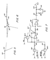
- the outlet check valve opening may be determined. In fact it may be easier to detect the check valve opening using system pressure if the change in the slope of the pump chamber pressure curve is slight or is obscured by "ringing" which normally accompanies the opening of the outlet check valve (see Fig. 6 and the accompanying text).
- detector 70 may comprise a "paddle wheel” or turbine which is driven by motion of the solvent, rotation of the wheel (or lack thereof) being suitably detected and transmitted to the computing part of the control circuit 66.
- a thin strain gauge or vane may be inserted into the fluid stream which is bent by the flow of solvent thereby changing its resistance, which change in resistance may be detected to determine the opening of outlet check valve 34.
- the output signal therefrom may be transmitted over line 72 to the computing part of the motor control circuit 66.
- the computing part 66 of the motor control circuit is a microprocessor, the motor speed control output thereof being applied to a step generator 65 which also has a 2 megahertz clock signal applied thereto, the output of the step generator being connected to a stepper motor drive circuit 69 which provides micro step pulses to the stepper motor at a rate determined by the microprocessor.
- the slope of the chamber pressure pump-up waveform 54-56 is determined and the point in time when this line would reach system pressure is taken as the point in time when the outlet check valve opens.
- Such procedure results in slight overcompensation of the flow deficit which is intended for reasons which will be hereinafter explained.
- either overcompensation or undercompensation is possible by judicious selection of an appropriate percentage of the system pressure and using this to indicate check valve opening as will be more fully explained hereafter.
- system pressure is sensed and stored by the microprocessor sampling pump chamber pressure through transducer 36 or transducer 70.
- the pump piston reaches the end of the pumping stroke and starts its refill cycle flag 20 interrupts the light to (or allowed light to fall on) photo detector 22 and provides a reset or reference pulse on line 27 to microprocessor 66.
- This reset or reference pulse is utilized to start a timer or counter 76 which may be internal to the microprocessor 66. This action starts the beginning of the time period T DF .
- the precise position of cam 8 may be determined.
- the microprocessor 66 commences to sample pump piston chamber pressure and continues to sample chamber pressure once every 1 millisecond thereafter.
- the slope of line 54-56 may be determined and the time when pump piston chamber pressure would reach any other pressure if the outlet check valve remained closed can be calculated.
- the time T DF may be determined. That time can then be substituted into equation (6) and the time period that the excess flow should continue may be calculated.
- the pressure to which the piston chamber pressure is extrapolated may be selected in several ways. Most simply, it may be a percentage of the pressure measured and stored prior to the closing of the outlet check valve. It could also be determined by calculating the pressure at which the straight line approximation of the system pressure and the piston chamber pressure would intersect. In single pump systems the system pressure can be assumed to decay exponentially to zero pressure when the outlet check valve is closed. A system time constant can be determined from the system resistance and compliance and used in the formula for exponential decay to approximate the system pressure at a time approximating the opening of the outlet check valve.
- the preferred embodiment actually utilizes a time when an extension of line 54-56 would be equal to the sampled delivery system pressure, i.e., point 74 in Fig. 2, as the end of the time period T DF or the opening of the outlet check valve 34.
- T DF is actually slightly longer by the time period T ER which represents the time period between the time when the outlet check valve actually opens and the time when T DF is assumed to terminate.
- This time period is very small and provides an overcalculation or indication of the flow deficiency Q DF and therefore a slight overcompensation for the reasons set forth hereinafter.
- Figs. 2 and 3 are in somewhat idealized form.
- the area of the pressure curve in the vicinity of point 50 or the point at which piston ends its delivery stroke is shown in greater detail.
- the system pressure actually follows piston chamber pressure for a very short period of time and then starts to slowly decrease, the slope thereof being primarily dependent upon column resistance and the compliance of the pulse dampener. The reason for this is that as the piston commences its refill stroke a small amount of fluid from the system flows back into the piston chamber prior to actual closing of the check valve.
- Q DF is slightly greater than the quantity calculated utilizing the idealized form of Fig.
- the preferred embodiment utilizes the point in time where the line 54-56 would intersect the original system pressure so that T DF is slightly longer than actual. It should be recognized that by judicious selection of the parameters which are used to determine the end of the time period T DF , which approximate the opening of the outlet check valve, over or undercompensation may be obtained. For example if the system pressure drop-out during refill is small and, one utilizes the point at which chamber pressure reaches 90% of stored system pressure as the time of outlet check valve opening undercompensation will occur while by selection of the 110% point, overcompensation will occur.
- FIG. 7-9 An alternate embodiment utilizing an analog circuit rather than a microprocessor to calculate T EX from T DF in real time is illustrated in Figs. 7-9. It is a fundamental theory of this invention to drive the pump at a high rate for a time period after the outlet check valve opens to create an excess flow in the system equal to the deficiency in the flow while the pump was in the refill and piston chamber pump-up portion of the cycle and thus satisfy equation 4.
- T EX can be readily determined in this general case by integrating a voltage V D proportional to F D for a time T DF and then integrating a voltage -V EX proportional to -F EX until the integrator reaches its starting value, typically zero volts. These voltages are typically available in analog circuits in which a servo motor is used to drive the pump. During normal delivery a voltage V D is applied to the servo and at other times the voltage V D +V EX is applied. T EX would be equal to the time required for the integrator to reach its starting value after the integrated voltage was switched from V D to -V EX .
- Fig. 8 illustrates this integration for the special case where F EX is constant, i.e., that the motor is being driven at a constant rate during the excess flow time period.
- the voltage V D is connected through switch SW1 and resistor 82 to the inverting terminal of an integrator which comprises an operational amplifier 84 and capacitor 86 connected between the output and the inverting terminal, switch SW3 being connected across capacitor 86.
- the other terminal of the integrator is connected to circuit ground.
- the voltage -V EX Also connected to the inverting terminal of the integrator through switch SW2 and resistor 83 is the voltage -V EX .
- Resistor 83 will have the same valve as resistor 82.
- the output of the integrator is connected through resistor 88 to the positive input of a comparator 90 having a fixed voltage V connected to its negative input terminal.
- a feedback resistor 92 is connected between the output and the positive input terminal of comparator 90.
- a series connected capacitor 94 and parallel connected resistor 96 and diode 98 for pulse shaping Connected to the output of comparator 90 is a series connected capacitor 94 and parallel connected resistor 96 and diode 98 for pulse shaping.
- the output terminal 100 of the circuit is connected to the reset terminal of the bistable flip-flop 102 of Fig. 9.
- Resistor 82 or resistor 83 and capacitor 86 determine the integrator time constant and resistors 88 and 92 provide hysteresis for the comparator.
- Fig. 7 subscripts are used which have been used heretofore to specify time intervals. High true logic levels are shown without a bar above the symbol and low true logic levels are designated with a bar above the symbol.
- the switches shown in Fig. 7 are high true, where true corresponds to closure.
- the "+" symbol designates the logic "OR” function.
- the voltage V is either ground or a voltage source that can be varied on either side of ground.
- DF is a logic level corresponding to the deficit flow time period T DF
- ND is a logic level corresponding to the time interval when the motor is at its normal delivery speed
- REX is a logic pulse corresponding to the end of the excess flow time period
- RFS is a logic pulse corresponding to the start of the refill time interval or the flag signal in Fig. 1. This symbol is not used in Fig. 7 but is utilized in Fig. 9
- switch SW1 is closed during the interval of deficit flow (DF is high) or during the normal delivery portion of the cycle (ND is high).
- SW1 is open only during system pump-up i.e. only during the excess flow period.
- Switch SW3 however is also closed during the normal delivery portion of the cycle and renders the integrator inoperative during this period.
- a voltage V D proportional to the deficit flow is being applied to the integrator and a negative going ramp (shown positive in Fig. 8) is generated at the integrator output as indicated by waveform 107.
- the integrator is ramped down at a rate proportional to the voltage V D during the time of deficit flow or when the outlet check valve is closed.
- the logic level DF + ND is applied to switch SW2.
- SW2 is closed when SW1 is open and vice versa and SW2 is closed only when the system is in the excess flow period.
- ND is low
- SW3 is open and the integrator is operative.
- voltage -V EX proportional to the excess flow rate is applied through switch SW2 to the integrator and the integrator ramps up as shown by waveform 107 (down in Fig. 8).
- the comparator provides an output pulse REX which indicates the end of the rapid system pump-up cycle.
- a bistable flip-flop 102 has applied to its set terminal the start of refill or flag signal RFS and to its reset terminal the output REX of the circuit of Fig. 7 i.e., a pulse indicating the end of the system pump-up period.
- RFS start of refill or flag signal
- REX output of the circuit of Fig. 7
- Q is high and Q is low.
- ND normal delivery speed
- the logic level ND can also be utilized by the external circuitry to switch the pump between its normal delivery speed corresponding to V D and its rapid speed corresponding to V D + V EX .
- the signal DF indicating that the outlet check valve is closed and that deficit flow is occurring is applied to the other terminal.
- the logic level DF may be generated through the use of another bistable flip-flop applying RSF to the set terminal and a pulse coinciding with the opening of the outlet check valve to the reset terminal.
- the pulse coinciding with the opening of the outlet check valve can be generated through the use of any of the methods previously described.
- the output of gate 104, DF + ND is applied to switch SW2 and to both inputs of a second NOR gate 106.
- the output of NOR gate 106, DF + ND is applied to switch SW1.
- the term "refill period” or the “refill portion of the stroke” as used herein includes the decompression period and not just the period when the inlet check valve is open and the pump chamber is being refilled.
- the portion of the compression stroke prior to outlet check valve opening has been termed “piston chamber pump-up” or “chamber pump-up” although certain of the prior art include this period within the term “refill”.
- the outlet check valve is closed the pump is “isolated” from the remainder of the fluid system and this period of no flow has been termed the deficit flow period.
- the time during which the pump is delivering an excess quantity of fluid to the system has been termed the compensation period or portion of the stroke in certain of the claims. This term is synonymous with the term system pump-up.
- predetermined when used in conjunction with flow, speed or velocity is not intended to mean constant and includes a known variable or programmed change. Moreover, unless expressly stated otherwise in the appended claims it is obvious that the speed of the drive motor during the refill, chamber pump-up and compensation periods, need not be either constant or the same and the term "predetermined” is intended to incompass such operation. For example, because of stepper motor torque considerations, it may be desirable to reduce motor speed below the refill speed but above the normal delivery speed and that speed change may come either prior to or during chamber pump-up, at the opening of the outlet check valve, or at some point in the compensation period, i.e. either before, at or after outlet check valve opening.
- valve in the appended claims is not intended to be so limited. From a commercial standpoint, while check valves may be the valve of choice because of cost, simplicity, ease of repair or replacement, one could utilize other types of valves, such as slider valves, and construct circuitry and sensing systems to open and close the valves at the proper points in the pump cycle.
Landscapes
- Physics & Mathematics (AREA)
- Health & Medical Sciences (AREA)
- Life Sciences & Earth Sciences (AREA)
- Chemical & Material Sciences (AREA)
- Analytical Chemistry (AREA)
- Biochemistry (AREA)
- General Health & Medical Sciences (AREA)
- General Physics & Mathematics (AREA)
- Immunology (AREA)
- Pathology (AREA)
- Engineering & Computer Science (AREA)
- Mechanical Engineering (AREA)
- General Engineering & Computer Science (AREA)
- Control Of Positive-Displacement Pumps (AREA)
- Reciprocating Pumps (AREA)
Claims (18)
- Strömungsmittelförder- bzw. -zufuhrsystem umfassend(a) wenigstens eine Pumpe (2) mit einem Kolben (4) für hin- und hergehende Bewegung innerhalb einer Pumpenkammer (6), sowie mit einem Strömungsmitteleinlaß und einem Strömungsmittelauslaß;(b) ein Einlaßventil (32), welches beim Saug- oder Füllhub des Kolbens öffnet und beim Pump- oder Förderhub schließt;(c) ein Auslaßventil (34), das beim Pump- oder Förderhub zur Förderung von Lösungsmittel an das System öffnet und beim Saug- oder Füllhub schließt;(d) einen Motor (12) zum Antrieb der genannten Pumpe und eine Motorsteuerschaltung (66), (76) zur Regelung der Motorgeschwindigkeit bzw. -drehzahl,dadurch gekennzeichnet,
daß das Strömungsmittelfördersystem des weiteren umfaßt:- Mittel zur Bestimmung der Länge der Zeit einer Defizitströmungsperiode (TDF), während welcher das Auslaßventil geschlossen ist;- wobei die Motorsteuerschaltung bewirkt, daß der genannte Motor den Kolben mit einer ersten vorgegebenen Geschwindigkeit bzw. Drehzahl antreibt zur Förderung von Strömungsmittel mit einem Förderdurchsatz (FD); sowie- Kompensationsmittel zum Antrieb des genannten Motors mit einer zweiten vorgegebenen Geschwindigkeit bzw. Drehzahl während einer Kompensationsperiode (TEX), die ausreicht um das Strömungsdefizit während der genannten Zeitdauer (TDF), in welcher das Auslaßventil geschlossen ist, zu kompensieren. - System nach Anspruch 1, bei welchem die genannten Kompensationsmittel so ausgebildet sind, daß die Kompensationsperiode (TEX) unmittelbar nach der Strömungsdefizitperiode (TDF) und vor der genannten normalen Förderperiode auftritt.
- System nach Anspruch 2, bei welchem die genannten Steuermittel (66),(76) des weiteren Mittel umfassen, welche den Motor (12) während wenigstens einem Teil der genannten Defizitperiode (TDF) mit einer dritten vorgegebenen Geschwindigkeit bzw. Drehzahl antreiben, die größer als die erste vorgegebene Geschwindigkeit bzw. Drehzahl ist.
- System nach Anspruch 3, bei welchem die genannten Steuermittel den genannten Motor während der gesamten genannten Defizit-Strömungsperiode auf der genannten dritten vorgegebenen Geschwindigkeit bzw. Drehzahl halten.
- System nach Anspruch 2, bei welchem die genannte erste und die genannte zweite vorgegebene Geschwindigkeit bzw. Drehzahl des genannten Motors (12) konstant sind.
- System nach Anspruch 3, bei welchem die genannte erste, zweite und dritte vorgegebene Geschwindigkeit bzw. Drehzahl des genannten Motors (12) konstant sind.
- System nach Anspruch 6, bei welchem die genannte zweite und dritte vorgegebene Geschwindigkeit bzw. Drehzahl des Motors (12) gleich groß sind.
- System nach Anspruch 1, bei welchem das Auslaßventil (34) ein Rückschlagventil ist und die genannten Mittel zur Bestimmung von TDF umfasssen:- Mittel (20),(22),(27) zur Erzeugung eines ersten Signals, sobald der genannte Kolben (14) seinen Füllhub beginnt und das genannte Auslaßrückschlagventil (34) schließt;- Mittel (60),(62) zur Erzeugung eines zweiten Signals etwa im Zeitpunkt, wenn das genannte Auslaßrückschlagventil (34) öffnet; sowie- Mittel (76) zur Bestimmung der Zeit zwischen dem genannten ersten und zweiten Signal.
- System nach Anspruch 8, bei welchem die genannten Mittel zur Erzeugung des zweiten Signals Mittel zum direkten Nachweis des Öffnens des genannten Auslaßrückschlagventils (34) umfassen.
- System nach Anspruch 9, bei welchem die genannten Mittel zur Erzeugung des zweiten Signals Mittel zur indirekten Bestimmung des Öffnungszeitpunkts des genannten Auslaßrückschlagventils (34) umfassen.
- System nach Anspruch 10, bei welchem die genannten Mittel zur indirekten Bestimmung des Zeitpunkts des Öffnens des genannten Auslaßrückschlagventils (34) umfassen:- Mittel (36),(66),(70) zur Bestimmung und Speicherung des Systemdrucks während der genannten normalen Förderungsperiode;- während der genannten Strömungsdefizitperiode (TDF) wirksame Mittel (66) zur Abfühlung und Festhaltung des Zeitpunkts und des Drucks, sobald der Druck in der Kolbenkammer (6) zwei vorgegebene Druckwerte, die kleiner als der gespeicherte Systemdruck sind, erreicht;- Mittel zur Bestimmung der Steigung der den Kolbendruckaufpumpvorgang wiedergebenden Kurve (54-56);- Mittel, welche die genannte ermittelte Steigung der Kurve des Kolbendruckaufpumpvorgangs zur Bestimmung des Zeitpunkts verwenden, in welchem der genannte Kolbenkammerdruck einen dem genannten gespeicherten Systemdruck proportionalen Wert erreichen würde, wenn das Auslaßrückschlagventil geschlossen bliebe; sowie- Rechenmittel, welche unter Verwendung der genannten ermittelten Zeitperiode die Länge der genannten Kompensationszeitperiode bestimmen.
- System nach Anspruch 11, bei welchem der proportionale Wert kleiner als der genannte abgefühlte Systemdruck ist.
- System nach Anspruch 11, bei welchem der genannte Proportionalwert größer als der genannte abgefühlte Systemdruck ist.
- System nach Anspruch 11, bei welchem der genannte Proportionalwert annähernd gleich dem genannten abgefühlten Systemdruck ist.
- Strömungsmittelförder- bzw. -zufuhrsystem gemäß einem der Ansprüche 1 bis 14, bei welchem die genannten Mittel zur Bestimmung von TDF einschließen:(a) Mittel zur Lösung der Gleichung
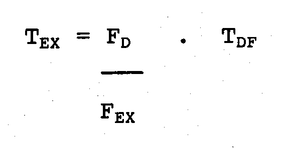 (b) und bei welchem die genannten Steuermittel des weiteren Mittel zum Antrieb des genannten Motors mit der genannten zweiten vorgegebenen Geschwindigkeit bzw. Drehzahl während annähernd der genannten Zeitperiode TEX umfassen, derart daß die Überschußmenge der Strömungsmittelförderung während der genannten Zeitperiode TEX annähernd gleich der Strömungsmittelmenge ist, welche während der Zeitperiode TDF gefördert worden wäre, wenn die genannte Vorrichtung während dieser Periode Strömungsmittel mit dem genannten normalen Förderdurchsatz gefördert hätte.
 - System nach Anspruch 15, bei welchem TDF die tatsächliche Zeitperiode übersteigt, derart daß die genannte Vorrichtung eine Überkompensation bezüglich des Strömungsdefizits bewirkt.
- System nach Anspruch 15, bei welchem TDF kleiner als die tatsächliche Zeitperiode ist, derart daß die genannte Vorrichtung eine Unterkompensation bezüglich des Strömungsdefizits bewirkt.
- System nach Anspruch 1, bei welchem die genannten Mittel zur Bestimmung von TDF umfassen:(a) Mittel zur Auflösung der Gleichung:

und(b) daß die genannten Steuermittel des weiteren Mittel zum Antrieb des genannten Motors mit der genannten zweiten vorgegebenen Geschwindigkeit bzw. Drehzahl während etwa der genannten Zeitperiode TEX einschließen, derart daß die während der genannten Zeitperiode TEX geförderte Überschuß-Strömungsmittelmenge annähernd gleich der Strömungsmittelmenge ist, die während der Zeitperiode TDF gefördert worden wäre, falls die Apparatur während dieser Zeitperiode mit dem genannten normalen Förderdurchsatz gefördert hätte.
Applications Claiming Priority (2)
| Application Number | Priority Date | Filing Date | Title |
|---|---|---|---|
| US21389 | 1987-03-03 | ||
| US07/021,389 US4919595A (en) | 1987-03-03 | 1987-03-03 | Fluid delivery system with deficit flow compensation |
Publications (3)
| Publication Number | Publication Date |
|---|---|
| EP0281294A2 EP0281294A2 (de) | 1988-09-07 |
| EP0281294A3 EP0281294A3 (en) | 1990-09-05 |
| EP0281294B1 true EP0281294B1 (de) | 1994-07-20 |
Family
ID=21803919
Family Applications (1)
| Application Number | Title | Priority Date | Filing Date |
|---|---|---|---|
| EP88301465A Expired - Lifetime EP0281294B1 (de) | 1987-03-03 | 1988-02-22 | Flüssigkeitsversorgungssystem mit Kompensation des Flussdefizits |
Country Status (4)
| Country | Link |
|---|---|
| US (1) | US4919595A (de) |
| EP (1) | EP0281294B1 (de) |
| JP (1) | JP2586925B2 (de) |
| DE (1) | DE3850688T2 (de) |
Families Citing this family (63)
| Publication number | Priority date | Publication date | Assignee | Title |
|---|---|---|---|---|
| GB2220369B (en) * | 1988-06-10 | 1993-01-27 | Inst Of Child Health | Method for testing body fluids by low pressure liquid chromatography |
| US5089124A (en) * | 1990-07-18 | 1992-02-18 | Biotage Inc. | Gradient generation control for large scale liquid chromatography |
| US5460091A (en) * | 1990-10-30 | 1995-10-24 | Como Technologies, Inc. | Printing press ink supply system |
| US5120199A (en) * | 1991-06-28 | 1992-06-09 | Abbott Laboratories | Control system for valveless metering pump |
| US5415489A (en) * | 1993-01-11 | 1995-05-16 | Zymark Corporation | Reciprocating driver apparatus |
| US5450743A (en) * | 1994-01-10 | 1995-09-19 | Zymark Corporation | Method for providing constant flow in liquid chromatography system |
| EP0753102A4 (de) * | 1994-03-29 | 1998-12-23 | Orbital Eng Pty | Pumpenkontrollsystem |
| US5630943A (en) * | 1995-11-30 | 1997-05-20 | Merck Patent Gesellschaft Mit Beschrankter Haftung | Discontinuous countercurrent chromatographic process and apparatus |
| US6364623B1 (en) * | 1996-05-29 | 2002-04-02 | Waters Investments Limited | Bubble detection and recovery in a liquid pumping system |
| US6106238A (en) * | 1998-10-02 | 2000-08-22 | Water Investments Limited | Bubble detection and recovery in a liquid pumping system |
| US6063284A (en) * | 1997-05-15 | 2000-05-16 | Em Industries, Inc. | Single column closed-loop recycling with periodic intra-profile injection |
| FR2763688A1 (fr) * | 1997-05-22 | 1998-11-27 | Gilson Sa | Dispositif pour detecter la circulation d'un fluide pour un ensemble d'analyse chromatographique |
| FR2763689B1 (fr) * | 1997-05-22 | 1999-08-13 | Gilson Sa | Procede pour fournir un fluide a un ensemble d'analyse chromatographique |
| DE19947443A1 (de) * | 1999-10-02 | 2001-04-05 | Messer Griesheim Gmbh | Kompressor für feuchte Gase |
| DE19961852A1 (de) * | 1999-12-22 | 2001-06-28 | Continental Teves Ag & Co Ohg | Pumpe mit geregeltem Ventil |
| US6635173B2 (en) * | 2000-12-28 | 2003-10-21 | Cohesive Technologies, Inc. | Multi column chromatography system |
| JP3823060B2 (ja) * | 2002-03-04 | 2006-09-20 | 株式会社日立製作所 | 高圧燃料供給ポンプ |
| US6997683B2 (en) * | 2003-01-10 | 2006-02-14 | Teledyne Isco, Inc. | High pressure reciprocating pump and control of the same |
| US20040204864A1 (en) * | 2003-04-09 | 2004-10-14 | Allington Robert W. | Signal to noise ratio in chromatography |
| US20040204866A1 (en) * | 2003-04-09 | 2004-10-14 | Allington Robert W. | Method and apparatus to enhance the signal to noise ratio in chromatography |
| US20040202575A1 (en) * | 2003-04-09 | 2004-10-14 | Allington Robert W. | Signal to noise ratio in chromatography |
| US20040205422A1 (en) * | 2003-04-09 | 2004-10-14 | Allington Robert W. | Signal to noise ratio in chromatography |
| US8313308B2 (en) * | 2004-03-26 | 2012-11-20 | Hospira, Inc. | Medical infusion pump with closed loop stroke feedback system and method |
| US8535016B2 (en) * | 2004-07-13 | 2013-09-17 | Waters Technologies Corporation | High pressure pump control |
| EP1846966A4 (de) * | 2005-02-03 | 2012-11-07 | Fleck Controls Inc | Steueranordnung für enthärter |
| FR2882528B1 (fr) * | 2005-02-25 | 2007-05-25 | Pic Solution Soc Par Actions S | Procede mixte de chromatographie en phase supercritique et installation pour sa mise en oeuvre |
| JP4709629B2 (ja) * | 2005-10-19 | 2011-06-22 | 株式会社日立ハイテクノロジーズ | ポンプ装置 |
| US20090053072A1 (en) * | 2007-08-21 | 2009-02-26 | Justin Borgstadt | Integrated "One Pump" Control of Pumping Equipment |
| US8517990B2 (en) | 2007-12-18 | 2013-08-27 | Hospira, Inc. | User interface improvements for medical devices |
| DE102009020414A1 (de) * | 2009-05-08 | 2010-11-11 | Lewa Gmbh | Vergleichmäßigung des Förderstroms bei oszillierenden Verdrängerpumpen |
| WO2011071528A2 (en) * | 2009-12-08 | 2011-06-16 | Graco Minnesota Inc. | System and method for controlling linear pump system |
| US8444314B2 (en) * | 2010-07-16 | 2013-05-21 | Petroleum Analyzer Company, Lp | Dampening apparatus and method for single piston pump used in determining the thermal stability of fluids |
| DE102010034585B4 (de) * | 2010-08-17 | 2016-04-07 | Lewa Gmbh | Vorrichtung zur Durchführung von Chromatografie |
| ES2605804T3 (es) | 2010-08-20 | 2017-03-16 | Graco Minnesota Inc. | Procedimiento para sincronizar un sistema de bombas lineales |
| US9222618B2 (en) | 2010-11-29 | 2015-12-29 | Lincoln Industrial Corporation | Stepper motor driving a lubrication pump providing uninterrupted lubricant flow |
| US9388940B2 (en) | 2010-11-29 | 2016-07-12 | Lincoln Industrial Corporation | Variable speed stepper motor driving a lubrication pump system |
| US9022177B2 (en) | 2010-11-29 | 2015-05-05 | Lincoln Industrial Corporation | Pump having stepper motor and overdrive control |
| CA2844807C (en) | 2011-08-19 | 2022-07-26 | Hospira, Inc. | Systems and methods for a graphical interface including a graphical representation of medical data |
| WO2013090709A1 (en) | 2011-12-16 | 2013-06-20 | Hospira, Inc. | System for monitoring and delivering medication to a patient and method of using the same to minimize the risks associated with automated therapy |
| JP6306566B2 (ja) | 2012-03-30 | 2018-04-04 | アイシーユー・メディカル・インコーポレーテッド | 注入システムのポンプ内の空気を検出するための空気検出システムおよび方法 |
| EP3586891B1 (de) | 2012-07-31 | 2025-04-09 | ICU Medical, Inc. | Patientenbehandlungssystem für kritische medikamente |
| CN104101669B (zh) * | 2013-04-10 | 2017-11-28 | 北京普源精仪科技有限责任公司 | 一种用于控制系统压力脉动的高效液相色谱仪 |
| AU2014268355B2 (en) | 2013-05-24 | 2018-06-14 | Icu Medical, Inc. | Multi-sensor infusion system for detecting air or an occlusion in the infusion system |
| ES2845748T3 (es) | 2013-05-29 | 2021-07-27 | Icu Medical Inc | Sistema de infusión y método de uso que impiden la sobresaturación de un convertidor analógico-digital |
| CA2913915C (en) | 2013-05-29 | 2022-03-29 | Hospira, Inc. | Infusion system which utilizes one or more sensors and additional information to make an air determination regarding the infusion system |
| US9284822B2 (en) * | 2013-07-05 | 2016-03-15 | Robert N. Ayres | Method for chemical treatment of a subsurface wellbore |
| CN105492041B (zh) * | 2013-08-30 | 2018-12-18 | Kpr美国有限责任公司 | 具有泵组冲洗和流量补偿的肠内输送泵 |
| US9671065B2 (en) | 2013-10-17 | 2017-06-06 | Lincoln Industrial Corporation | Pump having wear and wear rate detection |
| WO2015131108A2 (en) | 2014-02-28 | 2015-09-03 | Hospira, Inc. | Infusion system and method which utilizes dual wavelength optical air-in-line detection |
| US11344673B2 (en) | 2014-05-29 | 2022-05-31 | Icu Medical, Inc. | Infusion system and pump with configurable closed loop delivery rate catch-up |
| US11344668B2 (en) | 2014-12-19 | 2022-05-31 | Icu Medical, Inc. | Infusion system with concurrent TPN/insulin infusion |
| US10850024B2 (en) | 2015-03-02 | 2020-12-01 | Icu Medical, Inc. | Infusion system, device, and method having advanced infusion features |
| CA3023658C (en) | 2016-05-13 | 2023-03-07 | Icu Medical, Inc. | Infusion pump system and method with common line auto flush |
| AU2017277804B2 (en) | 2016-06-10 | 2022-05-26 | Icu Medical, Inc. | Acoustic flow sensor for continuous medication flow measurements and feedback control of infusion |
| US10089055B1 (en) | 2017-12-27 | 2018-10-02 | Icu Medical, Inc. | Synchronized display of screen content on networked devices |
| US11278671B2 (en) | 2019-12-04 | 2022-03-22 | Icu Medical, Inc. | Infusion pump with safety sequence keypad |
| AU2021311443A1 (en) | 2020-07-21 | 2023-03-09 | Icu Medical, Inc. | Fluid transfer devices and methods of use |
| US11135360B1 (en) | 2020-12-07 | 2021-10-05 | Icu Medical, Inc. | Concurrent infusion with common line auto flush |
| US12599716B2 (en) | 2021-10-12 | 2026-04-14 | Icu Medical, Inc. | Intravenous infusion pump with cassette insertion and pump control user interface |
| USD1091564S1 (en) | 2021-10-13 | 2025-09-02 | Icu Medical, Inc. | Display screen or portion thereof with graphical user interface for a medical device |
| CA3241894A1 (en) | 2021-12-10 | 2023-06-15 | Icu Medical, Inc. | Medical fluid compounding systems with coordinated flow control |
| CN114726471B (zh) * | 2022-03-21 | 2024-08-06 | 国网湖南省电力有限公司 | 基于hplc的配电场域网时钟精准同步方法及装置 |
| CN115684408B (zh) * | 2022-10-28 | 2025-02-18 | 浙江福立分析仪器股份有限公司 | 超高效液相色谱分析的控制方法、系统 |
Family Cites Families (21)
| Publication number | Priority date | Publication date | Assignee | Title |
|---|---|---|---|---|
| US31608A (en) * | 1861-03-05 | Improved swimming propeller | ||
| JPS4912401A (de) * | 1972-05-17 | 1974-02-02 | ||
| US3985021A (en) * | 1975-11-10 | 1976-10-12 | Varian Associates | High performance liquid chromatography system |
| US4045343A (en) * | 1975-11-10 | 1977-08-30 | Varian Associates, Inc. | High pressure liquid chromatography system |
| US4127360A (en) * | 1976-12-16 | 1978-11-28 | Carpenter Clarence W | Bumpless pump apparatus adjustable to meet slave system needs |
| USRE31608E (en) | 1977-01-21 | 1984-06-19 | Altex Scientific, Inc. | Fluid pump mechanism |
| US4137011A (en) * | 1977-06-14 | 1979-01-30 | Spectra-Physics, Inc. | Flow control system for liquid chromatographs |
| US4359312A (en) * | 1978-08-15 | 1982-11-16 | Zumtobel Kg | Reciprocating pump for the pulsation-free delivery of a liquid |
| FR2461126A1 (fr) * | 1978-12-15 | 1981-01-30 | Gilson Medical Electronic Fran | Pompe a piston a debit reglable precisement |
| US4255088A (en) * | 1979-06-14 | 1981-03-10 | Valleylab, Inc. | Liquid pumping system having means for detecting gas in the pump |
| US4321014A (en) * | 1979-12-31 | 1982-03-23 | Polaroid Corporation | Constant flow pumping apparatus |
| US4352636A (en) * | 1980-04-14 | 1982-10-05 | Spectra-Physics, Inc. | Dual piston pump |
| US4311586A (en) * | 1980-04-22 | 1982-01-19 | Tracor, Inc. | Solvent mixing in HPLC using low pressure solvent metering pumps |
| DE3035770C2 (de) * | 1980-09-23 | 1984-08-16 | Bruker Analytische Meßtechnik GmbH, 7512 Rheinstetten | Mehrfach-Kolbenpumpe mit konstanter Förderleistung |
| CA1186166A (en) * | 1982-02-27 | 1985-04-30 | Katsuhiko Saito | Liquid chromatograph |
| US4427298A (en) * | 1982-09-30 | 1984-01-24 | E. I. Du Pont De Nemours And Company | Method and system for accurately providing fluid blends |
| US4552513A (en) * | 1983-03-07 | 1985-11-12 | Spectra-Physics, Inc. | Multiple piston pump control |
| US4595496A (en) * | 1984-06-29 | 1986-06-17 | Millipore Corporation | Liquid composition control |
| FR2573136B1 (fr) * | 1984-11-15 | 1989-03-31 | Schlumberger Cie Dowell | Procede d'observation des caracteristiques de pompage sur une pompe a deplacement positif et pompe permettant de mettre en oeuvre ce procede. |
| US4808092A (en) * | 1986-01-08 | 1989-02-28 | Saphirwerk Industrieprodukte | Precision reciprocating metering pump |
| US4714545A (en) * | 1986-03-20 | 1987-12-22 | Hewlett-Packard Company | Fluid proportioning pump system |
-
1987
- 1987-03-03 US US07/021,389 patent/US4919595A/en not_active Expired - Lifetime
-
1988
- 1988-02-22 EP EP88301465A patent/EP0281294B1/de not_active Expired - Lifetime
- 1988-02-22 DE DE3850688T patent/DE3850688T2/de not_active Expired - Fee Related
- 1988-03-02 JP JP63049461A patent/JP2586925B2/ja not_active Expired - Lifetime
Also Published As
| Publication number | Publication date |
|---|---|
| EP0281294A2 (de) | 1988-09-07 |
| DE3850688D1 (de) | 1994-08-25 |
| DE3850688T2 (de) | 1994-10-27 |
| US4919595A (en) | 1990-04-24 |
| JP2586925B2 (ja) | 1997-03-05 |
| JPS63259183A (ja) | 1988-10-26 |
| EP0281294A3 (en) | 1990-09-05 |
Similar Documents
| Publication | Publication Date | Title |
|---|---|---|
| EP0281294B1 (de) | Flüssigkeitsversorgungssystem mit Kompensation des Flussdefizits | |
| US4137011A (en) | Flow control system for liquid chromatographs | |
| US4797834A (en) | Process for controlling a pump to account for compressibility of liquids in obtaining steady flow | |
| US4352636A (en) | Dual piston pump | |
| US4828464A (en) | Diaphragm pump device | |
| EP0303220B1 (de) | Verdrängerpumpe mit geringer Druckschwankung | |
| EP0217318B1 (de) | Verfahren und Vorrichtung für die Flüssigkeitschromatographie | |
| US3985019A (en) | Liquid chromatography system with solvent proportioning | |
| US3985021A (en) | High performance liquid chromatography system | |
| JP3221672B2 (ja) | ポンプ装置 | |
| US6997683B2 (en) | High pressure reciprocating pump and control of the same | |
| US4681513A (en) | Two-stage pump assembly | |
| US3981620A (en) | Pumping apparatus | |
| US4595496A (en) | Liquid composition control | |
| CN100386605C (zh) | 用于测量时间分辨的容积流动过程的装置 | |
| US4797207A (en) | Apparatus for controlling a pump to account for compressibility of liquids in obtaining steady flow | |
| US5040126A (en) | Method for predicting steady-state conditions | |
| JPS645254B2 (de) | ||
| CA2743053A1 (en) | Method and apparatus for a peristaltic pump | |
| US4420393A (en) | Pump for liquid chromatography and a chromatograph including the pump | |
| US3932067A (en) | Liquid chromatography apparatus and method | |
| US4772388A (en) | Apparatus for liquid chromatography | |
| US4882781A (en) | Method for predicting steady-state conditions | |
| US3958898A (en) | Pump control systems | |
| NL9101556A (nl) | Besturingssysteem voor zuigermembraanpomp. |
Legal Events
| Date | Code | Title | Description |
|---|---|---|---|
| PUAI | Public reference made under article 153(3) epc to a published international application that has entered the european phase |
Free format text: ORIGINAL CODE: 0009012 |
|
| AK | Designated contracting states |
Kind code of ref document: A2 Designated state(s): CH DE FR GB IT LI |
|
| PUAL | Search report despatched |
Free format text: ORIGINAL CODE: 0009013 |
|
| AK | Designated contracting states |
Kind code of ref document: A3 Designated state(s): CH DE FR GB IT LI |
|
| 17P | Request for examination filed |
Effective date: 19901106 |
|
| 17Q | First examination report despatched |
Effective date: 19920811 |
|
| GRAA | (expected) grant |
Free format text: ORIGINAL CODE: 0009210 |
|
| ITF | It: translation for a ep patent filed | ||
| AK | Designated contracting states |
Kind code of ref document: B1 Designated state(s): CH DE FR GB IT LI |
|
| REF | Corresponds to: |
Ref document number: 3850688 Country of ref document: DE Date of ref document: 19940825 |
|
| ET | Fr: translation filed | ||
| PGFP | Annual fee paid to national office [announced via postgrant information from national office to epo] |
Ref country code: CH Payment date: 19950420 Year of fee payment: 8 |
|
| PLBE | No opposition filed within time limit |
Free format text: ORIGINAL CODE: 0009261 |
|
| STAA | Information on the status of an ep patent application or granted ep patent |
Free format text: STATUS: NO OPPOSITION FILED WITHIN TIME LIMIT |
|
| 26N | No opposition filed | ||
| PG25 | Lapsed in a contracting state [announced via postgrant information from national office to epo] |
Ref country code: LI Effective date: 19960229 Ref country code: CH Effective date: 19960229 |
|
| REG | Reference to a national code |
Ref country code: CH Ref legal event code: PL |
|
| PGFP | Annual fee paid to national office [announced via postgrant information from national office to epo] |
Ref country code: GB Payment date: 19990108 Year of fee payment: 12 |
|
| PGFP | Annual fee paid to national office [announced via postgrant information from national office to epo] |
Ref country code: FR Payment date: 19990204 Year of fee payment: 12 |
|
| PGFP | Annual fee paid to national office [announced via postgrant information from national office to epo] |
Ref country code: DE Payment date: 19990226 Year of fee payment: 12 |
|
| PG25 | Lapsed in a contracting state [announced via postgrant information from national office to epo] |
Ref country code: GB Free format text: LAPSE BECAUSE OF NON-PAYMENT OF DUE FEES Effective date: 20000222 |
|
| GBPC | Gb: european patent ceased through non-payment of renewal fee |
Effective date: 20000222 |
|
| PG25 | Lapsed in a contracting state [announced via postgrant information from national office to epo] |
Ref country code: FR Free format text: LAPSE BECAUSE OF NON-PAYMENT OF DUE FEES Effective date: 20001031 |
|
| PG25 | Lapsed in a contracting state [announced via postgrant information from national office to epo] |
Ref country code: DE Free format text: LAPSE BECAUSE OF NON-PAYMENT OF DUE FEES Effective date: 20001201 |
|
| REG | Reference to a national code |
Ref country code: FR Ref legal event code: ST |
|
| PG25 | Lapsed in a contracting state [announced via postgrant information from national office to epo] |
Ref country code: IT Free format text: LAPSE BECAUSE OF NON-PAYMENT OF DUE FEES;WARNING: LAPSES OF ITALIAN PATENTS WITH EFFECTIVE DATE BEFORE 2007 MAY HAVE OCCURRED AT ANY TIME BEFORE 2007. THE CORRECT EFFECTIVE DATE MAY BE DIFFERENT FROM THE ONE RECORDED. Effective date: 20050222 |