EP0281321A2 - Verfahren und Apparat zum Behandeln von biologischen Flüssigkeiten - Google Patents
Verfahren und Apparat zum Behandeln von biologischen Flüssigkeiten Download PDFInfo
- Publication number
- EP0281321A2 EP0281321A2 EP88301630A EP88301630A EP0281321A2 EP 0281321 A2 EP0281321 A2 EP 0281321A2 EP 88301630 A EP88301630 A EP 88301630A EP 88301630 A EP88301630 A EP 88301630A EP 0281321 A2 EP0281321 A2 EP 0281321A2
- Authority
- EP
- European Patent Office
- Prior art keywords
- container
- driven
- enclosure
- coupling
- axis
- Prior art date
- Legal status (The legal status is an assumption and is not a legal conclusion. Google has not performed a legal analysis and makes no representation as to the accuracy of the status listed.)
- Withdrawn
Links
Images

Classifications
-
- B—PERFORMING OPERATIONS; TRANSPORTING
- B04—CENTRIFUGAL APPARATUS OR MACHINES FOR CARRYING-OUT PHYSICAL OR CHEMICAL PROCESSES
- B04B—CENTRIFUGES
- B04B9/00—Drives specially designed for centrifuges; Arrangement or disposition of transmission gearing; Suspending or balancing rotary bowls
- B04B9/12—Suspending rotary bowls ; Bearings; Packings for bearings
-
- B—PERFORMING OPERATIONS; TRANSPORTING
- B04—CENTRIFUGAL APPARATUS OR MACHINES FOR CARRYING-OUT PHYSICAL OR CHEMICAL PROCESSES
- B04B—CENTRIFUGES
- B04B5/00—Other centrifuges
- B04B5/04—Radial chamber apparatus for separating predominantly liquid mixtures, e.g. butyrometers
- B04B5/0442—Radial chamber apparatus for separating predominantly liquid mixtures, e.g. butyrometers with means for adding or withdrawing liquid substances during the centrifugation, e.g. continuous centrifugation
-
- B—PERFORMING OPERATIONS; TRANSPORTING
- B04—CENTRIFUGAL APPARATUS OR MACHINES FOR CARRYING-OUT PHYSICAL OR CHEMICAL PROCESSES
- B04B—CENTRIFUGES
- B04B5/00—Other centrifuges
- B04B5/04—Radial chamber apparatus for separating predominantly liquid mixtures, e.g. butyrometers
- B04B5/0442—Radial chamber apparatus for separating predominantly liquid mixtures, e.g. butyrometers with means for adding or withdrawing liquid substances during the centrifugation, e.g. continuous centrifugation
- B04B2005/0464—Radial chamber apparatus for separating predominantly liquid mixtures, e.g. butyrometers with means for adding or withdrawing liquid substances during the centrifugation, e.g. continuous centrifugation with hollow or massive core in centrifuge bowl
Definitions
- This invention relates to a method and apparatus for processing biological fluids, such as blood or suspended cells, and, more specifically, to a disposable centrifuge apparatus in which biological fluids may be separated by being centrifuged.
- the centrifugal force separates the lighter density biological components from the heavier density biological components.
- red blood cells which are heavier, may be separated from plasma or platelet components which are lighter in density.
- Latham Bowl comprises a rotor in the form of a bowl body which is mounted on a chuck and which is adapted to rotate about a longitudinal axis extending through the bowl.
- a core member may be provided within the bowl body to provide a zone between the bowl body and the core, within which the blood is separated into constituent components by the centrifugal forces acting on the blood.
- Whole blood is introduced into the bowl via a fixed, or stationary, feed tube mounted on a header.
- the feed tube extends into the bowl and is coaxial with the longitudinal axis of the bowl body.
- An outlet, or effluent port is formed coaxially about the inlet port to allow separated blood components to flow out of the centrifuge bowl.
- the inlet and outlet ports are connected to fixed members.
- the inlet port may be connected through sterile tubing to a phlebotomy needle, which may be inserted into a donor for collection of blood.
- the outlet port may be connected, through sterile tubing, to a sterilized plasma collection container. Because of these connections, both of these ports must remain stationary and cannot be rotated along with the centrifuge bowl.
- Latham Bowl-type blood centrifuge processors have required some form of rotating seal between the stationary inlet and outlet ports and the rotating centrifuge bowl.
- an improved rotary seal which has a rotatable ring member and a non-rotatable ring member with sealing surfaces in sealing engagement with each other and wherein means are provided to entrap solid particulate matter on the side of the seal toward the blood pathway which may be generated at areas of contact between the two ring members during operation of the centrifuge. Further, means are provided for directing entrapped particles back to the area of contact between the ring members, so that the particles are ingested and expelled to the outside.
- the "skip-rope" seal-less centrifuge is shown in Fig. 2 of U. S. Patent 4,146,172 to Cullis et al.
- this apparatus comprises a rotor drive assembly to which a rotor assembly is journaled by means of a hollow support shaft.
- the rotor drive assembly is itself journaled to a stationary hub assembly by means of a vertical drive shaft.
- a red blood cell separation chamber and a platelet collection chamber are seated on the rotor assembly. Fluid communication is established between the two chambers, which rotate with the rotor assembly, and the non-rotating portions of the processing system, by means of an umbilical cable which extends from a central location along the axis of rotation of the rotor downwardly through the center of the drive shaft, radially outwardly through a guide sleeve, and upwardly to a fixed axially aligned position established by a support arm.
- the routing of the umbilical cable, together with the rotor assembly and rotor drive assembly are driven in the same direction with a speed ratio of 2:1, to establish fluid communication between the two chambers without the cable becoming twisted. Variations of this "skip-rope" technique are shown in U. S. Patents 4,425,112, 4,419,089 and 3,775,309.
- the "skip-rope” technique carries its own associated drawbacks.
- the system is hard to load, requires a large diameter machine for orbiting an arm at half the rotation speed.
- Such large diameter machines are bulky and awkward, considering the intended use environment, i.e., hospitals.
- Such machines use a complicated medium gear mechanism and results in wear of the "skip-rope” tubing.
- a method and apparatus for processing blood, or other biological fluids in which an enclosed, disposable, rotatable, fluid processing centrifuge bowl or container, is provided.
- This container has a driven member affixed thereto which is adapted to rotate about an axis in response to rotary motion coupled from a drive member.
- a non-rotational enclosure is provided about the rotatable container and the driven member to form a fluid-tight seal completely around the rotatable container, thereby preventing outside contaminants from reaching the inside of the container, or vice versa.
- the non-rotational enclosure is comprised of three basic items.
- the first is a fixed member through which one or more non-rotatable inlet and outlet fluid ports extend into the container.
- the inlet port(s) provide a sterilizable pathway for fluids to be passed into the container for centrifugal separation into constituent components.
- the outlet port(s) provide a sterilizable pathway for the separated components to flow out of the container.
- An opening is formed on said fixed member, through which a mechanical force, in the form of rotational motion, is imparted to the driven member.
- An orbiting coupling member forms the second basic item of the enclosure.
- the coupling member couples, or transfers, rotational motion to the driven member from an external drive member.
- the coupling member is itself non-rotationally translatable about the bowl axis; that is, it orbits about the bowl axis, but does not rotate.
- the third item of the enclosure comprises a flexible tubular member, or boot, extending from the axial opening in the fixed member to the coupling member for forming a fluid-tight seal around the axial opening and the coupling member.
- Rotary motion of the drive member is applied to the coupling member, where it is converted, or translated, by the coupling member into a non-rotational orbiting motion and then back to rotary motion of the driven member affixed to the rotatable bowl.
- rotary motion from an external drive motor is coupled through a fixed, or stationary, outer enclosure to cause rotary motion of a centrifuge bowl, or container, within the fixed member; without requiring a rotary seal and the resultant problems associated therewith.
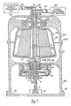
- a rotary drive motor 12 is coupled to a drive shaft 2, preferably aligned with the bowl axis A.
- Shaft 2 is rotationally coupled to cylindrical rotary drive member 4.
- Cylindrical rotary drive member 4 has an eccentric bore 7 extending to surface 7A.
- a driven shaft 18 is affixed to the rotatable bowl 40 and is also longitudinally aligned with the bowl axis A opposite drive shaft 2.
- Plate 3 is concentrically mounted on driven shaft 18.
- a pin 5 is formed in an eccentric bore on plate 3 and extends into a concentric bore 8B in coupling device 8.
- a bearing surface is provided at the interface of pin 5 and bore 8B.
- device 8 is a cylindrical graphite member having a concentric bore 8B on one side and a protruding cylindrical stud 8A on an opposite side. Stud 8A seats in the eccentric bore 7 of member 4. A bearing surface is formed at the interface between stud 8A and bore 7.
- Device 8 is thus removably and slideably mounted in rotary cylinder device member 4, making the entire assembly above member 4 part of a sterile disposable blood processing kit.
- the lower assembly comprising member 4, shaft 2, drive motor 12 and plate 60, may be retained and repeatedly used with new disposables.
- a flexible boot 16 (See Fig. 2) of resilient impermeable material, such as silicone or rubber, extends from the upper periphery of device 8 to the lower periphery of alignment base 6.
- Boot 16 thus forms a flexible fluid-tight enclosure about the periphery of device 8 and the shaft opening for the driven member through fixed enclosure 20.
- Boot 16 flexes as device 8 orbits about axis A.
- a fixed plastic envelope 20 completes the air-tight path about the entire centrifuge bowl 40. This air-tight path prevents airborne contaminants, such as bacteria, from entering the bowl 40, so that once the interior of the bowl, and associated processing set(s) and conduits, is sterilized, in a conventional manner, they will remain sterilized.
- An optional alignment base 6 retains lower bearings 42, and mates with a circular channel 44 formed on cross member 20C of enclosure 20.
- Enclosure 20 may be conveniently comprised of an upper and lower plastic, transparent, spherical shell 20U and 20L, respectively, joined together at flanges 20F, which may be bonded together in a well-known manner.
- a centrifuge bowl 40 Prior to bonding the upper half 20U of the enclosure to the lower half 20L, a centrifuge bowl 40 is mounted on driven member 18, such as by being pinned or otherwise affixed in a conventional manner.
- the centrifuge rotor or bowl 40 may comprise a bowl-shape member 50 having top upper vertical portion 50U to which is attached upper bearings 44. Bearings 44 and 42 hold the centrifuge bowl 40 in a rotatable fashion about the central longitudinal axis A of the drive axle 2.
- An optional core member 14 is affixed to the inner centrifuge bowl 40, in the conventional manner, and input and output ports 32 and 30 in header 90 are attached or formed to, or on, the fixed enclosure 20.
- the ports are provided with central passageways 31 and 28 concentric with the longitudinal axis of the bowl 40.
- the enclosure 20 may optionally be provided with lower skirts 20L and removably mounted on base plate 60 by bolts 62. In this manner, a completely self-contained transportable centrifuge is provided with no exposed rotating parts, and in which no separate external containment device is required to contain biological fluids, in the event the bowl 40 should rupture in operation.
- the outer enclosure 20 is preferably made of plastic material, such as polycarbonate. As previously stated, the enclosure 20, with the bowl 40, coupling member 8, boot 16, and associated hardware, forms a disposable assembly. After use, this assembly may be removed and discarded by sliding the assembly out of the bore 7 in drive cylinder 4 after unbolting the enclosure from base plate 60.
- anticoagulated whole blood such as blood from a donor
- the whole blood is coupled via tubing 82 to input port 32.
- the whole blood passes through input port 32 down longitudinal passageway 28 into the bottom of the centrifuge bowl 40.
- Driven member 18 is rotated by engaging drive motor 12 coupled by coupling member 8 to shaft 18.
- the bowl rotates and the whole blood is caused, by centrifugal force to move outwardly through pathway 27 against the inner walls of the centrifuge bowl 40 between the core 14 and the inner walls 50I of the bowl body 50.
- a sterile processing receiver set 86 such as a plasmapheresis bag or a plateletpheresis bag for storage; or may be returned to the donor.
- the enclosed bowl with coupling means 8 may be connected by tubing to blood processing sets 80 and 86 and the entire disposable system sterilized in a conventional manner prior to being seated in the drive cylinder 4; thus assuring complete sterility of the system in advance of usage.
- boot 16 is a low profile, one-piece flexible member, having a central opening 16A, which forms a snap-on fluid tight fit 16A around the periphery of graphite coupling device 8.
- U-shaped cross-sections 16U provide necessary lateral flexibility to permit device 8 to orbit about the central bowl axis A, yet retain a fluid tight seal.
- the inner peripheral surface 16I of boot 16 forms a fluid tight fit which is bonded to the outer periphery 6B of extension ring 6R of base 6.
- Base 6 has a central opening 6A within which bearings 42 are mounted for rotatably supporting driven member 18.
- a circular channel 6C is formed in base 6. This channel mates with a circular projection 44 in cross-piece 20C to align the boot and coupling member with the fixed enclosure 20.
- Additional inlet and outlet ports may be readily provided by insertion through enclosure 20 for introducing or extracting processing fluids, since no rotary seals are required. Conversely, a single port may be used for introduction and expulsion of fluids.
- the drive motor 12, and associated coupling members, need not be aligned with the bowl axis, but may be offset using conventional gearing mechanisms.
Landscapes
- Centrifugal Separators (AREA)
- External Artificial Organs (AREA)
Applications Claiming Priority (2)
| Application Number | Priority Date | Filing Date | Title |
|---|---|---|---|
| US21338 | 1987-03-03 | ||
| US07/021,338 US4767396A (en) | 1987-03-03 | 1987-03-03 | Method and apparatus for processing biological fluids |
Publications (2)
| Publication Number | Publication Date |
|---|---|
| EP0281321A2 true EP0281321A2 (de) | 1988-09-07 |
| EP0281321A3 EP0281321A3 (de) | 1989-09-27 |
Family
ID=21803642
Family Applications (1)
| Application Number | Title | Priority Date | Filing Date |
|---|---|---|---|
| EP88301630A Withdrawn EP0281321A3 (de) | 1987-03-03 | 1988-02-25 | Verfahren und Apparat zum Behandeln von biologischen Flüssigkeiten |
Country Status (3)
| Country | Link |
|---|---|
| US (1) | US4767396A (de) |
| EP (1) | EP0281321A3 (de) |
| JP (1) | JPS63267458A (de) |
Cited By (2)
| Publication number | Priority date | Publication date | Assignee | Title |
|---|---|---|---|---|
| AU615571B2 (en) * | 1988-09-02 | 1991-10-03 | Ciba-Geigy Ag | Synergistic Mixture |
| WO2008049212A1 (en) * | 2006-10-23 | 2008-05-02 | Mcalister Steven A | Centrifugal concentrator |
Families Citing this family (47)
| Publication number | Priority date | Publication date | Assignee | Title |
|---|---|---|---|---|
| US5045048A (en) * | 1990-03-29 | 1991-09-03 | Haemonetics Corporation | Rotary centrifuge bowl and seal for blood processing |
| DK119490D0 (da) * | 1990-05-14 | 1990-05-14 | Unes As | Apparat til fremstilling af et koncentrat af koagulationsfaktorer, saasom fibrinogen, fra en blodportion |
| DK167517B1 (da) * | 1991-11-11 | 1993-11-15 | Squibb & Sons Inc | Beholder til optagelse og adskillelse af en vaeske, fortrinsvis blodplasma, i dennes bestanddele |
| CH687505A5 (fr) * | 1993-01-29 | 1996-12-31 | Elp Rochat | Séparateur centrifuge pour fluides. |
| ZA948564B (en) * | 1993-11-19 | 1995-07-26 | Bristol Myers Squibb Co | Liquid separation apparatus and method |
| US5514070A (en) * | 1994-01-21 | 1996-05-07 | Haemonetics Corporation | Plural collector centrifuge bowl for blood processing |
| US5733253A (en) * | 1994-10-13 | 1998-03-31 | Transfusion Technologies Corporation | Fluid separation system |
| PL320511A1 (en) * | 1994-12-02 | 1997-10-13 | Bristol Myers Squibb Co | Method of and apparatus for isolating fibrin i from blood plasma |
| WO1996016713A1 (en) * | 1994-12-02 | 1996-06-06 | E.R. Squibb And Sons, Inc. | Centrifuge reagent delivery system |
| US5733446A (en) * | 1994-12-02 | 1998-03-31 | Bristol-Myers Squibb Company | Centrifuge with annular filter |
| US5658231A (en) * | 1995-09-21 | 1997-08-19 | Haemonetics Corporation | Mechanism for securing a separation bowl to a mechanical chuck |
| US6140040A (en) * | 1995-10-06 | 2000-10-31 | Advanced Minerals Corporation | Method of mechanically separating microparticles suspended in fluids using particulate media |
| DE19543088C1 (de) * | 1995-11-18 | 1997-03-06 | Heraeus Instr Gmbh | Laborzentrifuge |
| US5964690A (en) * | 1997-03-19 | 1999-10-12 | Medtronic, Inc. | Mechanism for fixing a blood centrifuge bowl to a rotating spindle |
| WO1998052629A2 (en) * | 1997-05-20 | 1998-11-26 | Zymequest, Inc. | Cell processing systems |
| US6852074B1 (en) * | 1997-05-20 | 2005-02-08 | Zymequest, Inc. | Biological processing apparatus for expressing fluid material |
| US6629919B2 (en) * | 1999-06-03 | 2003-10-07 | Haemonetics Corporation | Core for blood processing apparatus |
| EP1057534A1 (de) * | 1999-06-03 | 2000-12-06 | Haemonetics Corporation | Zentrifugentrommel mit Filterkern |
| US6602413B2 (en) | 2000-04-11 | 2003-08-05 | Medicept, Inc. | Sealed centrifugal clarifier |
| US20030040835A1 (en) * | 2001-04-28 | 2003-02-27 | Baxter International Inc. | A system and method for managing inventory of blood component collection soft goods in a blood component collection facility |
| US7211037B2 (en) | 2002-03-04 | 2007-05-01 | Therakos, Inc. | Apparatus for the continuous separation of biological fluids into components and method of using same |
| US7479123B2 (en) | 2002-03-04 | 2009-01-20 | Therakos, Inc. | Method for collecting a desired blood component and performing a photopheresis treatment |
| US7074172B2 (en) * | 2002-08-02 | 2006-07-11 | Zymequest, Inc. | Processing bag for component separator system and method of removing separated components |
| US7476209B2 (en) | 2004-12-21 | 2009-01-13 | Therakos, Inc. | Method and apparatus for collecting a blood component and performing a photopheresis treatment |
| TWM269966U (en) * | 2005-01-21 | 2005-07-11 | Tian-Ju Ruan | Plasmapheresis centrifuge bowl |
| EP1683579A1 (de) * | 2005-01-25 | 2006-07-26 | Jean-Denis Rochat | Einweggerät zur kontinuierlichen Trennung einer physiologischen Flüssigkeit mittels Zentrifugieren |
| US7998052B2 (en) * | 2006-03-07 | 2011-08-16 | Jacques Chammas | Rotor defining a fluid separation chamber of varying volume |
| US8702637B2 (en) | 2008-04-14 | 2014-04-22 | Haemonetics Corporation | System and method for optimized apheresis draw and return |
| US8454548B2 (en) | 2008-04-14 | 2013-06-04 | Haemonetics Corporation | System and method for plasma reduced platelet collection |
| US8628489B2 (en) | 2008-04-14 | 2014-01-14 | Haemonetics Corporation | Three-line apheresis system and method |
| US8834402B2 (en) | 2009-03-12 | 2014-09-16 | Haemonetics Corporation | System and method for the re-anticoagulation of platelet rich plasma |
| EP2635320B1 (de) | 2010-11-05 | 2015-03-18 | Haemonetics Corporation | System und verfahren zur automatisierten thrombozytenwäsche |
| US9302042B2 (en) | 2010-12-30 | 2016-04-05 | Haemonetics Corporation | System and method for collecting platelets and anticipating plasma return |
| US11386993B2 (en) | 2011-05-18 | 2022-07-12 | Fenwal, Inc. | Plasma collection with remote programming |
| US11878312B2 (en) * | 2011-11-21 | 2024-01-23 | Pneumatic Scale Corporation | Centrifuge system for separating cells in suspension |
| US12350686B2 (en) * | 2011-11-21 | 2025-07-08 | Pneumatic Scale Corporation | Centrifuge system for separating cells in suspension |
| US20140047986A1 (en) | 2012-08-15 | 2014-02-20 | Cyclone Medtech, Inc. | Systems and methods for blood recovery from absorbent surgical materials |
| EP3180074B1 (de) | 2014-08-11 | 2018-07-04 | Medtronic, Inc. | Mechanische durchführungen für implantierbare medizinische vorrichtung |
| US10792416B2 (en) | 2017-05-30 | 2020-10-06 | Haemonetics Corporation | System and method for collecting plasma |
| US10758652B2 (en) | 2017-05-30 | 2020-09-01 | Haemonetics Corporation | System and method for collecting plasma |
| US11065376B2 (en) | 2018-03-26 | 2021-07-20 | Haemonetics Corporation | Plasmapheresis centrifuge bowl |
| US11412967B2 (en) | 2018-05-21 | 2022-08-16 | Fenwal, Inc. | Systems and methods for plasma collection |
| US12033750B2 (en) | 2018-05-21 | 2024-07-09 | Fenwal, Inc. | Plasma collection |
| KR102345761B1 (ko) | 2018-05-21 | 2022-01-03 | 펜월, 인크. | 혈장 수집 체적의 최적화를 위한 시스템 |
| US10683478B1 (en) * | 2019-05-16 | 2020-06-16 | Shenzhen Eureka biotechnology Co. Ltd | Device and system for processing a liquid sample containing cells |
| US11957998B2 (en) * | 2019-06-06 | 2024-04-16 | Pneumatic Scale Corporation | Centrifuge system for separating cells in suspension |
| CN110448751B (zh) * | 2019-07-26 | 2023-08-29 | 北京中科盛康科技有限公司 | 一种自体血液回收器 |
Family Cites Families (22)
| Publication number | Priority date | Publication date | Assignee | Title |
|---|---|---|---|---|
| GB337659A (en) * | 1929-12-12 | 1930-11-06 | Kodak Ltd | Improved means for imparting variable velocity to a shaft |
| US2536793A (en) * | 1945-03-02 | 1951-01-02 | Separator Ab | Sealing device for centrifugal separators |
| US3317127A (en) * | 1945-03-02 | 1967-05-02 | Little Inc A | Centrifuge |
| US2497867A (en) * | 1945-07-09 | 1950-02-21 | Cymmer Thomas | Moistureproof construction for shafts |
| GB873137A (en) * | 1958-06-18 | 1961-07-19 | Dewrance & Co | Improvements in motion transmitting means |
| FR1248634A (fr) * | 1959-10-20 | 1960-12-23 | Joint tournant à soufflet étanche ou organe analogue d'étanchéité | |
| US3208289A (en) * | 1962-08-08 | 1965-09-28 | Hutter Ernest | Rotary shaft construction with diaphragm type of seal |
| US3371059A (en) * | 1963-02-21 | 1968-02-27 | Teknika Inc | Monomer stripping |
| US3145713A (en) * | 1963-09-12 | 1964-08-25 | Protein Foundation Inc | Method and apparatus for processing blood |
| US3409213A (en) * | 1967-01-23 | 1968-11-05 | 500 Inc | Rotary seal and centrifuge incorporation |
| US3565330A (en) * | 1968-07-11 | 1971-02-23 | Cryogenic Technology Inc | Rotary seal and centrifuge incorporating same |
| US3706412A (en) * | 1971-07-28 | 1972-12-19 | Haemonetics Corp | Pressure-actuated centrifuge chuck and centrifuge incorporating the same |
| US3801142A (en) * | 1972-06-30 | 1974-04-02 | Ibm | Fluid coupling |
| US3775309A (en) * | 1972-07-27 | 1973-11-27 | Department Of Health Education | Countercurrent chromatography with flow-through coil planet centrifuge |
| US3785549A (en) * | 1972-07-31 | 1974-01-15 | Haemonetics Corp | Centrifuge chuck for disposable, snap-in centrifuge rotor |
| US4425112A (en) * | 1976-02-25 | 1984-01-10 | The United States Of America As Represented By The Department Of Health And Human Services | Flow-through centrifuge |
| US4120448A (en) * | 1977-06-08 | 1978-10-17 | Baxter Travenol Laboratories, Inc. | Centrifugal liquid processing apparatus with automatically positioned collection port |
| US4419089A (en) * | 1977-07-19 | 1983-12-06 | The United States Of America As Represented By The Department Of Health And Human Services | Blood cell separator |
| US4146172A (en) * | 1977-10-18 | 1979-03-27 | Baxter Travenol Laboratories, Inc. | Centrifugal liquid processing system |
| DE2966488D1 (en) * | 1978-07-17 | 1984-01-19 | Haemonetics Corp | Centrifuge having a rotary seal |
| US4300717A (en) * | 1979-04-02 | 1981-11-17 | Haemonetics Corporation | Rotary centrifuge seal |
| US4353499A (en) * | 1981-04-27 | 1982-10-12 | Edward Simonds | Centrifugal separator |
-
1987
- 1987-03-03 US US07/021,338 patent/US4767396A/en not_active Expired - Fee Related
-
1988
- 1988-02-25 EP EP88301630A patent/EP0281321A3/de not_active Withdrawn
- 1988-03-02 JP JP63047647A patent/JPS63267458A/ja active Pending
Cited By (3)
| Publication number | Priority date | Publication date | Assignee | Title |
|---|---|---|---|---|
| AU615571B2 (en) * | 1988-09-02 | 1991-10-03 | Ciba-Geigy Ag | Synergistic Mixture |
| WO2008049212A1 (en) * | 2006-10-23 | 2008-05-02 | Mcalister Steven A | Centrifugal concentrator |
| US8343025B2 (en) | 2006-10-23 | 2013-01-01 | Steven A. McAlister | Centrifugal concentrator with suspended rotor bowl |
Also Published As
| Publication number | Publication date |
|---|---|
| US4767396A (en) | 1988-08-30 |
| JPS63267458A (ja) | 1988-11-04 |
| EP0281321A3 (de) | 1989-09-27 |
Similar Documents
| Publication | Publication Date | Title |
|---|---|---|
| US4767396A (en) | Method and apparatus for processing biological fluids | |
| EP0019038B1 (de) | Verfahren und Vorrichtung zur zentrifugalen Behandlung von Flüssigkeiten | |
| US4303193A (en) | Apparatus for separating blood into components thereof | |
| US4285464A (en) | Apparatus for separation of blood into components thereof | |
| US5100372A (en) | Core for blood processing apparatus | |
| US3885735A (en) | Centrifuge apparatus | |
| EP0062038B1 (de) | Zentrifugen-behandlungsgerät sowie rotierender behandlungsbehälter | |
| AU720556B2 (en) | Separation set for blood component preparation | |
| US4530691A (en) | Centrifuge with movable mandrel | |
| US5776336A (en) | Annular filter assembly | |
| CA1316513C (en) | Blood centrifugation cell | |
| EP0194271B1 (de) | Geschlossenes hemapherese-system | |
| US4511349A (en) | Ultracentrifuge tube with multiple chambers | |
| JP2796821B2 (ja) | 血液成分採取セットおよび装置 | |
| US4091989A (en) | Continuous flow fractionation and separation device and method | |
| EP0587257B1 (de) | Verfahren und Vorrichtung zur Unwuchtverhinderung während der Trennung und Isolierung von Blut-oder Knochenmarkbestandteilen | |
| US8617042B2 (en) | Methods for separating constituents of biologic liquid mixtures | |
| AU2009225367B2 (en) | Multiple processing chamber set and use thereof | |
| US6709377B1 (en) | System and method for quick disconnect centrifuge unit | |
| JPH0683802B2 (ja) | 遠心分離セル | |
| WO1987006857A1 (en) | Annular centrifuge | |
| US6007472A (en) | Variable volume cell saver bowl | |
| WO1994000169A1 (en) | Device and system for blood separation | |
| JPS6229070Y2 (de) | ||
| IL121003A (en) | Method for separating liquids |
Legal Events
| Date | Code | Title | Description |
|---|---|---|---|
| PUAI | Public reference made under article 153(3) epc to a published international application that has entered the european phase |
Free format text: ORIGINAL CODE: 0009012 |
|
| AK | Designated contracting states |
Kind code of ref document: A2 Designated state(s): DE FR GB IT |
|
| PUAL | Search report despatched |
Free format text: ORIGINAL CODE: 0009013 |
|
| RHK1 | Main classification (correction) |
Ipc: B04B 9/08 |
|
| AK | Designated contracting states |
Kind code of ref document: A3 Designated state(s): DE FR GB IT |
|
| STAA | Information on the status of an ep patent application or granted ep patent |
Free format text: STATUS: THE APPLICATION IS DEEMED TO BE WITHDRAWN |
|
| 18D | Application deemed to be withdrawn |
Effective date: 19900328 |