EP0281361A2 - Support de charges creuses et procédé pour son assemblage - Google Patents
Support de charges creuses et procédé pour son assemblage Download PDFInfo
- Publication number
- EP0281361A2 EP0281361A2 EP88301771A EP88301771A EP0281361A2 EP 0281361 A2 EP0281361 A2 EP 0281361A2 EP 88301771 A EP88301771 A EP 88301771A EP 88301771 A EP88301771 A EP 88301771A EP 0281361 A2 EP0281361 A2 EP 0281361A2
- Authority
- EP
- European Patent Office
- Prior art keywords
- charge
- carrier
- retaining means
- opening
- deformable retaining
- Prior art date
- Legal status (The legal status is an assumption and is not a legal conclusion. Google has not performed a legal analysis and makes no representation as to the accuracy of the status listed.)
- Granted
Links
Images





Classifications
-
- E—FIXED CONSTRUCTIONS
- E21—EARTH OR ROCK DRILLING; MINING
- E21B—EARTH OR ROCK DRILLING; OBTAINING OIL, GAS, WATER, SOLUBLE OR MELTABLE MATERIALS OR A SLURRY OF MINERALS FROM WELLS
- E21B43/00—Methods or apparatus for obtaining oil, gas, water, soluble or meltable materials or a slurry of minerals from wells
- E21B43/11—Perforators; Permeators
- E21B43/116—Gun or shaped-charge perforators
- E21B43/117—Shaped-charge perforators
Definitions
- the invention relates to a carrier for carrying shaped charges for use in an elongated perforating gun of the type generally use to perforate oil and gas wells.
- Perforating guns commonly used in wire line and tubing conveyed service operations for perforating an oil or gas well typically include an elongated cylindrical outer housing within which is received an elongated carrier which has a number of shaped charges in place in the carrier.
- the carrier is located relative to the housing so as to position each of the shaped charges adjacent reduced thickness portions of the housing.
- Lug and slot type connection means have been utilized as shown in U.S. Patent No. 3,078,797 to Blair wherein the lugs of a shaped charge are inserted through an opening adjacent a carrier, and then the shaped charge is rotated to lock it in place relative to the carrier.
- wire-type carriers have been utilized wherein the shaped charge has spaced shoulders which receive the carrier wires therebetween, as shown in U.S. Patent No. 3,636,875 to Dodson.
- the carrier includes resilient tab means extending into openings for receiving the shaped charges.
- the resilient tab means frictionally engage the shaped charge as it is pushed into the opening and thereby hold the shaped charge in place within the opening.
- Such structures are shown for example in our European patent specification no. 175439, and in our U.S. Patents Nos. 4,609,057 and 4,621,396.
- the present invention provides a much improved, very economical, reliable, and easily assembled construction for the assembly of a shaped charge with a carrier.
- the present invention provides a shaped charge carrier apparatus, comprising: a thin wall carrier having a charge opening disposed therethrough for freely receiving a shaped charge therein; and deformable retaining means, integrally formed in said thin wall carrier adjacent a periphery of said charge opening, for initially allowing said shaped charge to be freely received in said charge opening and for subsequently retaining said shaped charge in said charge opening upon deformation of said deformable retaining means.
- the invention provides a shaped charge carrier assembly apparatus for use in a perforating gun comprising at least one shaped charge including an outer case, said case having a generally cylindrical outer surface having first and second oppositely facing annular shoulders defined thereon; a carrier having a substantially circular charge opening disposed therethrough large enough to receive said generally cylindrical outer surface of said case with said first annular shoulder abutting said carrier; and deformable retaining means, permanently attached to said carrier adjacent a periphery of said charge opening, for engaging said second annular shoulder upon deformation of said deformable retaining means to thereby retain said shaped charge in said charge opening.
- the invention provides a method of assembling a shaped charge carrier apparatus for use in a perforating gun, said method comprising the steps of:
- the shaped charge carrier design of the invention is particularly adaptable for use on a cylindrical tubular carrier and provides a means for mounting the shaped charges which reliably holds the shaped charges in a radial orientation relative to the carrier. This permits openings to be formed in substantially any desired pattern on the tubular carrier for mounting of the shaped charges.
- the perforating gun 10 includes an elongated cylindrical outer housing 12, the upper end of which is closed by a top plug 14 and the lower end of which is closed by a bottom plug 16.
- Top plug 14 is threadedly connected to housing 12 at threaded connection 18 and a seal is provided therebetween by the O-rings 20 and 22.
- the bottom plug 16 is threadedly connected to housing 12 at the threaded connection 24 and a resilient seal is provided therebetween by O-rings 26 and 28.
- the carrier 34 illustrated in FIG. 1 is a cylindrical charge carrier having a pattern of openings like that further illustrated in FIGS. 7-10, but it will be understood that any of the various charge carriers disclosed herein might be utilized with a perforating gun like the perforating gun 10.
- the present invention is applicable to charge carriers used without an enclosed housing.
- Such unenclosed charge carriers are used with shaped charges which are themselves constructed so as to withstand the downhole environment.
- the carrier 34 has disposed through the walls thereof a plurality of charge openings 36 for receiving shaped charges 38 therein.
- the carrier 34 is attached to the end plates 30 and 32 in such a manner as to specifically define its orientation about its longitudinal axis relative to the housing 12, so that each of the shaped charges 38 is located immediately adjacent a reduced thickness portion 40 of the housing 12 in a manner well known to those skilled in the art.
- a firing means 44 Disposed through a central opening 42 of top plug 14 is a firing means 44 which generally comprises a length of detonating cord and associated apparatus for firing the shaped charges 38 in response to an electrical signal directed down a wire line (not shown) from a surface location at the top of the oil well which is being perforated.
- the firing means 44 extends downward through the carrier 34 and is operatively connected to each of the shaped charges 38.
- the present invention can be used with any shape carrier, e.g., round tubular carriers, polygonal cross section tubular carriers, flat strip type carriers, or the like.
- shape carrier e.g., round tubular carriers, polygonal cross section tubular carriers, flat strip type carriers, or the like.
- charge openings and shaped charges can be arranged in any desired pattern, e.g., spiraled, multiple spirals, staggered layers, etc.
- the carrier is designated as 34A
- the charge openings are designated as 36A
- the shaped charges themselves are designated as 38A, corresponding to the general designations 34, 36 and 38 shown in FIG. 1.
- the original shape of the charge opening 36A is shown as it is formed in a flat thin wall sheet 46.
- a number of such openings will be formed in a flat sheet 46, and then the sheet 46 is rolled to a cylindrical configuration as seen in cross section in FIG. 4 thus forming the cylindrical thin wall carrier 34A.
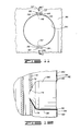
- FIG. 3 shows an enlarged elevation partial view of the cylindrical carrier 34A showing one of the charge openings 36A in elevation.
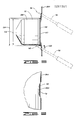
- FIG. 5 is a sectioned elevation partial view taken along 5-5 of FIG. 4 which further illustrates the manner in which the shaped charge 38A is held within the charge opening 36A of charge carrier 34A.
- the shaped charged 38A includes an outer case 50 having a generally cylindrical outer surface 52.
- the shaped charge 38A further includes first and second tapered frustoconical reduced diameter portions 62 and 64, and a radially inner end 66.
- the charge opening 36A of carrier 34A is a substantially circular charge opening (as best seen in FIG. 3) which is large enough to receive the generally cylindrical outer surface 52 of the case 50 with the first annular shoulder 54 abutting the carrier 34A.
- the substantially circular charge opening 36A has a reduced diameter portion at diameter 68.
- the reduced diameter portion 68 is located approximately in and adjacent a plane normal to a longitudinal central axis 70 (see FIG. 1) of the tubular carrier 34A. This results in the first annular shoulder 54 of shaped charge 38A abutting the carrier 34A at two pairs of diametrically opposed points 72 and 74 on an inner periphery of the reduced diameter portion 68 of the charge opening 36A.
- the first annular shoulder 54 rests on four points of support along the periphery of the charge opening 36A.
- the reduced diameter portion 68 of charge opening 36A is formed by two diametrically opposed arcuate edge portions 76 and 78 along the periphery of charge opening 36A, and the points 72, 74 are defined as the circumferential ends 72, 74 of each of the arcuate edge portions 76 and 78.
- first and second diametrically opposed deformable retaining means 80 and 82 Integrally formed with and permanently attached to the carrier 34A adjacent the periphery of the charge opening 36A are first and second diametrically opposed deformable retaining means 80 and 82.
- the charge opening 36A initially has a diametrical clearance 84 between the first and second deformable retaining means 80 and 82, sufficiently large that the generally cylindrical outer surface 52 of shaped charge 38A may be freely received therebetween.
- the deformable retaining means 80 and 82 Upon subsequent deformation of the first and second deformable retaining means 80 and 82, as further described below, the deformable retaining means 80 and 82 will move further into the charge opening 36A to retain the shaped charge 38A in place within the charge opening 36A as best illustrated in FIG. 5.
- the carrier 34A has a plurality of tool receiving apertures such as 86 disposed therethrough adjacent each of the deformable retaining means such as 80 and 82, so that the deformable retaining means 80 and 82 are at least partially defined between the tool receiving apertures 86 and the charge opening 36A.
- the tool receiving apertures 86 are completely separate from the charge opening 36A in this embodiment, although they need not be so completely separate in the broader concepts of the invention.
- the deformable retaining means such as 80 and 82 each include a relatively flexible beam portion 88 having two ends 90 and 92, both of which are integrally formed with and fixed to the thin wall carrier 34A.
- the beam portion 88 is defined between the tool receiving aperture 86 and the charge opening 36A.
- the deformable retaining means 80 and 82 each further include a tab portion 94 attached to the beam portion 88 between the two ends 90 and 92 thereof.
- the tab portion 94 extends from the beam portion 88 toward the charge opening 36A.
- the tool receiving apertures 86 are further defined as elongated slots oriented substantially parallel to a length of the beam portion 88 of the deformable retaining means 80, and substantially tangential to a closest point on the periphery of charge opening 36A.
- the beam portion 88 of the lower deformable retaining means 94 is torsionally flexible so that upon insertion of a thin bladed tool, such as the screwdriver 96 shown in phantom lines, into the tool receiving aperture 86 and rotation of said tool about an axis of rotation parallel to the length of the beam portion 88 of deformable retaining means 82, with an inserted end 98 of the tool 96 moving toward the charge opening 36A, the beam portion 88 of flexible retaining means 82 is bowed toward the charge opening 36A, and the beam portion 88 of deformable retaining means 82 is also torsionally rotated in a direction 100 opposite to that in which the tool 96 was rotated, thus moving the tab portion 94 away from the plane of the thin wall carrier 34A in the same direction as which the tool 96 was inserted into the tool receiving aperture 86, i.e., radially inward relative to the cylindrical carrier 34A.
- a thin bladed tool such as the screwdriver 96 shown
- a second manner of deforming the deformable retaining means such as 80 and 82 is illustrated at the upper part of FIG. 5 with regard to the upper deformable retaining means 80.
- the deformable retaining means 80 is deformed in a very different manner.
- the beam portion 88 When the tool 96 is rotated about an axis parallel to the length of the beam portion 88 of upper deformable retaining means 80 with the inserted end 98 moving away from the charge opening 36A, the beam portion 88 is bowed toward the charge opening 36A so that the tab portion 94 extends into the charge opening 36A, and the beam portion 88 is further bowed away from the plane of the thin wall carrier 34 radially inward to engage and hold the shoulder 56 of the radially outer end 60 of the shaped charge 38A.
- a distance between the first and second shoulders 54 and 56 is such that, and the carrier 34A and charge opening 36A are so dimensioned that, when the first annular shoulder 54 abuts the four support points 72, 74 on the periphery of the reduced diameter portion 68 of the charge opening 36A, the second annular shoulder 56 is located radially inward of the deformable retaining means 80 and 82.
- deformable retaining means 80 and 82 are shown in this embodiment as initially extending toward the opening 36A in a direction substantially parallel to the axis 70, they need not be so oriented.
- similar deformable retaining means could be located at approximately the location of arcuate edge portions 76 and 78, and could be engaged with an under- cut groove (not shown) in the outer surface of a shaped charge in a manner analogous to that shown in Fig. 14.
- the dimensions of the charge opening 36A of Fig. 3 are as follows.
- the charge opening 36A has a nominal inside diameter 106 of 1.820 inch (46.2mm).
- the reduced diameter portion 68 of charge opening 36A has a reduced diameter of 1.715 inch (43.6mm).
- the diameter 84 between the tabs 94 is 1.820 inch (46.2mm) prior to deformation of the deformable retaining means 80 and 82.
- the tool receiving slot shaped apertures 86 have a length of 3/4 inch (19.1mm) and a width of 1/8 inch (3.2mm). A distance 108 between the aperture 86 and the root 110 of the indentations defining the tabs 94 is 0.090 inch (2.29mm). Further, the thin wall carrier 34A is formed from a 16 Ga A366 cold rolled steel.
- FIGS. 7-10 illustrate an embodiment of the present invention similar to that shown in Figs. 2-6, but constructed for use with a modified shaped charge 38B best seen in FIG. 9.
- the shaped charge 38B has a generally cylindrical outer surface 122 defined along the length thereof.
- First and second oppositely facing annular shoulder 124 and 126 define a radially outwardly extending flange means 128 located intermediately along the length of the shaped charge 38B.
- the first annular shoulder 124 of flange means 128 rests on the four circumferential end points 130, 132, 134 and 136 of reduced diameter arcuate edge portions 138 and 140 of the generally circular charge opening 36B as seen in FIG. 8.
- the end points 130, 132, 134 and 136 can generally be referred to four points of support for the first annular shoulder 124 of shaped charge 38B.
- Upper and lower deformable retaining means 142 and 144 are constructed generally similar to the deformable retaining means 80 and 82 previously described with regard to FIG. 3. Similar tool receiving apertures 146 are also provided.
- the arcuate reduced diameter edge portions 138 and 140 are considerably longer in their circumferential span, to accommodate the modified shaped charge 38B.
- FIGS. 11 and 12 Another embodiment of the present invention is shown in FIGS. 11 and 12, which provides another form of cylindrical tubular charge carrier 34C for receiving a modified shaped charge 38C in a charge opening 36C.
- the charge opening 36C seen in elevation in FIG. 11 is a substantially uninterrupted circle of uniform diameter.
- Tool receiving apertures 152 and 154 are also provided.
- Upper and lower deformable retaining means 148 and 150 are defined between the tool receiving apertures 152 and 154, respectively, and the circular charge receiving opening 36C.
- Each of the upper and lower deformable retaining means 148 and 150 includes a relatively flexible beam portion having two ends such as 156 and 158 which are integrally formed with and fixed to the thin wall carrier 34C.
- each of the upper and lower deformable retaining means 148 and 150 are deformable into the charge opening 36C upon application of a force to a mid portion such as at points 160 and 162, thereof, said force being directed from the tool receiving apertures 152 and 154 toward the charge opening 36C.
- a suitable tool for deforming the deformable retaining means 148 and 150 of FIG. 11 is a flat bladed screwdriver having a 90° bend in the shank of the tool.
- the flat blade of the screwdriver can be inserted into the tool receiving aperture 152 or 154 and then rotated about an axis extending radially relative to the cylindrical carrier 34C to bow the deformable retaining means 148 and 150 outward into the shapes indicated in phantom lines in FIG. 11.
- the carrier 34C further includes second tool receiving openings 164 and 166 associated with the upper and lower deformable retaining means 148 and 150, respectively.
- the second tool receiving openings are spaced from the elongated slots 152 and 154 on a side thereof opposite the charge opening 36C so that a pair of pliers or the like can be engaged with the second tool receiving openings such as 164 and the beam portion of the deformable retaining means to deform the beam portion away from the charge opening and back toward its initial position.
- These second tool receiving openings 164 and 166 are utilized in the manner described above to allow the shaped charge 36C to be removed from the carrier 34C.
- FIG. 12 is an elevation sectioned partial view taken along line 12-12 of FIG. 11 showing the shaped charge 38C in place within the carrier 34C and illustrating how deformable retaining means 148 and 150 function.
- the upper retaining means 148 has not yet been deformed.
- the lower retaining means 150 has been deformed in FIG. 12 to a position like that shown in phantom lines in FIG. 11.
- the upper retaining means 148 is also deformed inward, the shaped charge 38C will be securely held within the carrier 34C.
- the shaped charge 38C has a generally cylindrical outer surface 168 the entirety of which can be received through the initially circular opening 36C.
- the cylindrical carrier 34C has associated therewith an inner charge holder tube 170 shown in cross section which is located concentrically within the cylindrical carrier 34C.
- the tube 170 has a longitudinal axial bore 172 disposed therethrough for receiving a prima cord or the like.
- the charge holder tube 170 further includes a plurality of frustoconical radially oriented openings such as 174 for receiving a complementary angled frustoconical nose portion 176 of the shaped charge 38C.
- the upper and lower deformable retaining means 148 and 150 are deformed to the position shown in phantom lines in FIG. 11 and the shaped charge 38C is thus held in place within the carrier 34C.
- FIGS. 13 and 14 show a charge receiving opening 36D somewhat similar to the charge receiving opening 36C of FIG. 11, in that the charge receiving opening 36D is a substantially uniform circle of constant diameter.
- the carrier 34D is a flat strip type carrier.
- Upper and lower deformable retaining means 178 and 180 are defined between the charge opening 36D and upper and lower tool receiving apertures 182 and 184 in a manner similar to that previously described.
- a shaped charge 38D has a generally cylindrical outer surface 186 with an enlarged diameter flange 188 defined at a radially outer end 190 thereof, with an undercut groove 192 of reduced diameter adjacent the flange 166.
- the circular flange 188 has a diameter greater than the diameter of the circular charge opening 36D so that a first annular shoulder or surface 194 thereof abuts the surface 196 of charge carrier 34D upon insertion of the shaped charge 38D into the opening 36D. Subsequently, the deformable retaining means 178 and 180 are bowed into the circular opening 36D and received within the groove 192.
- the lower deformable retaining means 180 is shown in a deformed position wherein it is received within the groove 192.
- One side of the groove 192 is defined by a second annular shoulder 198 of shaped charge 38D, and this second annular shoulder 198 will engage the upper and lower deformable retaining means 178 and 180 to retain the shaped charge 38D in place in the charge opening 36D.
Landscapes
- Life Sciences & Earth Sciences (AREA)
- Engineering & Computer Science (AREA)
- Geology (AREA)
- Mining & Mineral Resources (AREA)
- Physics & Mathematics (AREA)
- Environmental & Geological Engineering (AREA)
- Fluid Mechanics (AREA)
- General Life Sciences & Earth Sciences (AREA)
- Geochemistry & Mineralogy (AREA)
- Toys (AREA)
- Slide Fasteners, Snap Fasteners, And Hook Fasteners (AREA)
- Chair Legs, Seat Parts, And Backrests (AREA)
Applications Claiming Priority (2)
| Application Number | Priority Date | Filing Date | Title |
|---|---|---|---|
| US07/022,158 US4800815A (en) | 1987-03-05 | 1987-03-05 | Shaped charge carrier |
| US22158 | 1987-03-05 |
Publications (3)
| Publication Number | Publication Date |
|---|---|
| EP0281361A2 true EP0281361A2 (fr) | 1988-09-07 |
| EP0281361A3 EP0281361A3 (en) | 1989-03-22 |
| EP0281361B1 EP0281361B1 (fr) | 1993-02-10 |
Family
ID=21808115
Family Applications (1)
| Application Number | Title | Priority Date | Filing Date |
|---|---|---|---|
| EP88301771A Expired - Lifetime EP0281361B1 (fr) | 1987-03-05 | 1988-03-01 | Support de charges creuses et procédé pour son assemblage |
Country Status (7)
| Country | Link |
|---|---|
| US (1) | US4800815A (fr) |
| EP (1) | EP0281361B1 (fr) |
| AU (1) | AU607468B2 (fr) |
| CA (1) | CA1314765C (fr) |
| DE (1) | DE3878269D1 (fr) |
| MY (1) | MY102199A (fr) |
| NO (1) | NO880976L (fr) |
Families Citing this family (61)
| Publication number | Priority date | Publication date | Assignee | Title |
|---|---|---|---|---|
| US4915029A (en) * | 1987-03-05 | 1990-04-10 | Halliburton Company | Shaped charge carrier assembly method |
| US4875413A (en) * | 1988-11-30 | 1989-10-24 | Jet Research Center, Inc. | Apparatus for perforating wells |
| US5271943A (en) * | 1989-10-27 | 1993-12-21 | Scott Health Care | Wound gel compositions containing sodium chloride and method of using them |
| US5862758A (en) * | 1993-01-15 | 1999-01-26 | Schlumberger Technology Corporation | Insert and twist method and apparatus for securing a shaped charge to a loading tube of a perforating gun |
| US5648635A (en) * | 1995-08-22 | 1997-07-15 | Lussier; Norman Gerald | Expendalble charge case holder |
| US6012525A (en) | 1997-11-26 | 2000-01-11 | Halliburton Energy Services, Inc. | Single-trip perforating gun assembly and method |
| US6460463B1 (en) * | 2000-02-03 | 2002-10-08 | Schlumberger Technology Corporation | Shaped recesses in explosive carrier housings that provide for improved explosive performance in a well |
| US6487973B1 (en) * | 2000-04-25 | 2002-12-03 | Halliburton Energy Services, Inc. | Method and apparatus for locking charges into a charge holder |
| US7942098B2 (en) * | 2006-08-29 | 2011-05-17 | Schlumberger Technology Corporation | Loading tube for shaped charges |
| US12203350B2 (en) | 2013-07-18 | 2025-01-21 | DynaEnergetics Europe GmbH | Detonator positioning device |
| US9702680B2 (en) | 2013-07-18 | 2017-07-11 | Dynaenergetics Gmbh & Co. Kg | Perforation gun components and system |
| CN105492721B (zh) | 2013-08-26 | 2018-10-02 | 德国德力能有限公司 | 射孔枪和雷管组件 |
| CA2941648C (fr) | 2014-03-07 | 2022-08-16 | Dynaenergetics Gmbh & Co. Kg | Dispositif et procede de positionnement d'un detonateur dans un ensemble perforateur |
| WO2017014740A1 (fr) * | 2015-07-20 | 2017-01-26 | Halliburton Energy Services Inc. | Perforateur de puits à faible interférence et débris réduits |
| US10443361B2 (en) | 2017-03-27 | 2019-10-15 | IdeasCo LLC | Multi-shot charge for perforating gun |
| US10000994B1 (en) * | 2017-03-27 | 2018-06-19 | IdeasCo LLC | Multi-shot charge for perforating gun |
| US10746003B2 (en) * | 2017-08-02 | 2020-08-18 | Geodynamics, Inc. | High density cluster based perforating system and method |
| US11905823B2 (en) | 2018-05-31 | 2024-02-20 | DynaEnergetics Europe GmbH | Systems and methods for marker inclusion in a wellbore |
| US10458213B1 (en) * | 2018-07-17 | 2019-10-29 | Dynaenergetics Gmbh & Co. Kg | Positioning device for shaped charges in a perforating gun module |
| US12031417B2 (en) | 2018-05-31 | 2024-07-09 | DynaEnergetics Europe GmbH | Untethered drone string for downhole oil and gas wellbore operations |
| US11408279B2 (en) | 2018-08-21 | 2022-08-09 | DynaEnergetics Europe GmbH | System and method for navigating a wellbore and determining location in a wellbore |
| US11591885B2 (en) | 2018-05-31 | 2023-02-28 | DynaEnergetics Europe GmbH | Selective untethered drone string for downhole oil and gas wellbore operations |
| US10794159B2 (en) | 2018-05-31 | 2020-10-06 | DynaEnergetics Europe GmbH | Bottom-fire perforating drone |
| US11661824B2 (en) | 2018-05-31 | 2023-05-30 | DynaEnergetics Europe GmbH | Autonomous perforating drone |
| US10386168B1 (en) | 2018-06-11 | 2019-08-20 | Dynaenergetics Gmbh & Co. Kg | Conductive detonating cord for perforating gun |
| USD903064S1 (en) | 2020-03-31 | 2020-11-24 | DynaEnergetics Europe GmbH | Alignment sub |
| US11808093B2 (en) | 2018-07-17 | 2023-11-07 | DynaEnergetics Europe GmbH | Oriented perforating system |
| US11339614B2 (en) | 2020-03-31 | 2022-05-24 | DynaEnergetics Europe GmbH | Alignment sub and orienting sub adapter |
| WO2020038848A1 (fr) | 2018-08-20 | 2020-02-27 | DynaEnergetics Europe GmbH | Système et procédé de déploiement et de commande de dispositifs autonomes |
| USD1034879S1 (en) | 2019-02-11 | 2024-07-09 | DynaEnergetics Europe GmbH | Gun body |
| USD1010758S1 (en) | 2019-02-11 | 2024-01-09 | DynaEnergetics Europe GmbH | Gun body |
| USD1019709S1 (en) | 2019-02-11 | 2024-03-26 | DynaEnergetics Europe GmbH | Charge holder |
| US11400885B2 (en) * | 2019-03-29 | 2022-08-02 | GM Global Technology Operations LLC | Compact, lightweight and reusable local energy absorbers |
| US12116871B2 (en) | 2019-04-01 | 2024-10-15 | DynaEnergetics Europe GmbH | Retrievable perforating gun assembly and components |
| US12241326B2 (en) | 2019-05-14 | 2025-03-04 | DynaEnergetics Europe GmbH | Single use setting tool for actuating a tool in a wellbore |
| US10927627B2 (en) | 2019-05-14 | 2021-02-23 | DynaEnergetics Europe GmbH | Single use setting tool for actuating a tool in a wellbore |
| US11255147B2 (en) | 2019-05-14 | 2022-02-22 | DynaEnergetics Europe GmbH | Single use setting tool for actuating a tool in a wellbore |
| US11578549B2 (en) | 2019-05-14 | 2023-02-14 | DynaEnergetics Europe GmbH | Single use setting tool for actuating a tool in a wellbore |
| WO2020249744A2 (fr) | 2019-06-14 | 2020-12-17 | DynaEnergetics Europe GmbH | Ensemble perforateur doté d'un support de charge creuse rotatif |
| EP3999712A1 (fr) | 2019-07-19 | 2022-05-25 | DynaEnergetics Europe GmbH | Outil de puits de forage à actionnement balistique |
| US11946728B2 (en) | 2019-12-10 | 2024-04-02 | DynaEnergetics Europe GmbH | Initiator head with circuit board |
| WO2021122797A1 (fr) | 2019-12-17 | 2021-06-24 | DynaEnergetics Europe GmbH | Système de perforateur modulaire |
| WO2021185749A1 (fr) | 2020-03-16 | 2021-09-23 | DynaEnergetics Europe GmbH | Adaptateur d'étanchéité en tandem avec matériau traceur intégré |
| USD1041608S1 (en) | 2020-03-20 | 2024-09-10 | DynaEnergetics Europe GmbH | Outer connector |
| USD981345S1 (en) | 2020-11-12 | 2023-03-21 | DynaEnergetics Europe GmbH | Shaped charge casing |
| US11988049B2 (en) | 2020-03-31 | 2024-05-21 | DynaEnergetics Europe GmbH | Alignment sub and perforating gun assembly with alignment sub |
| USD904475S1 (en) | 2020-04-29 | 2020-12-08 | DynaEnergetics Europe GmbH | Tandem sub |
| USD908754S1 (en) | 2020-04-30 | 2021-01-26 | DynaEnergetics Europe GmbH | Tandem sub |
| US20220018224A1 (en) * | 2020-07-20 | 2022-01-20 | Geodynamics, Inc. | Multi-layer loading tube for perforating gun |
| US11732556B2 (en) | 2021-03-03 | 2023-08-22 | DynaEnergetics Europe GmbH | Orienting perforation gun assembly |
| US11713625B2 (en) | 2021-03-03 | 2023-08-01 | DynaEnergetics Europe GmbH | Bulkhead |
| US12366142B2 (en) | 2021-03-03 | 2025-07-22 | DynaEnergetics Europe GmbH | Modular perforating gun system |
| WO2022184732A1 (fr) | 2021-03-03 | 2022-09-09 | DynaEnergetics Europe GmbH | Cloison et adaptateur d'étanchéité double |
| US12000267B2 (en) | 2021-09-24 | 2024-06-04 | DynaEnergetics Europe GmbH | Communication and location system for an autonomous frack system |
| US12253339B2 (en) | 2021-10-25 | 2025-03-18 | DynaEnergetics Europe GmbH | Adapter and shaped charge apparatus for optimized perforation jet |
| US12312925B2 (en) | 2021-12-22 | 2025-05-27 | DynaEnergetics Europe GmbH | Manually oriented internal shaped charge alignment system and method of use |
| WO2023200984A1 (fr) | 2022-04-15 | 2023-10-19 | Dbk Industries, Llc | Outil de réglage à volume fixe |
| WO2024013338A1 (fr) | 2022-07-13 | 2024-01-18 | DynaEnergetics Europe GmbH | Outil de libération de câble entraîné par gaz |
| US11753889B1 (en) | 2022-07-13 | 2023-09-12 | DynaEnergetics Europe GmbH | Gas driven wireline release tool |
| US12546194B2 (en) | 2023-08-04 | 2026-02-10 | DynaEnergetics Europe GmbH | Method and apparatus for automatic arming of perforating gun |
| US20250327385A1 (en) * | 2024-04-19 | 2025-10-23 | Greenwell Engineering, Inc. | Addressable switch and orienting device adaptor for a perforating gun |
Family Cites Families (12)
| Publication number | Priority date | Publication date | Assignee | Title |
|---|---|---|---|---|
| US3078797A (en) * | 1960-11-08 | 1963-02-26 | Schlumberger Well Surv Corp | Strip gun improvements |
| US3636875A (en) * | 1970-06-29 | 1972-01-25 | Schlumberger Technology Corp | Shaped charge devices for wire carriers |
| US4326462A (en) * | 1979-09-21 | 1982-04-27 | Schlumberger Technology Corporation | Shaped charge retention and barrier clip |
| US4312273A (en) * | 1980-04-07 | 1982-01-26 | Shaped Charge Specialist, Inc. | Shaped charge mounting system |
| US4598775A (en) * | 1982-06-07 | 1986-07-08 | Geo. Vann, Inc. | Perforating gun charge carrier improvements |
| US4479556A (en) * | 1982-10-04 | 1984-10-30 | Baker Oil Tools, Inc. | Subterranean well casing perforating gun |
| US4583602A (en) * | 1983-06-03 | 1986-04-22 | Dresser Industries, Inc. | Shaped charge perforating device |
| US4655138A (en) * | 1984-09-17 | 1987-04-07 | Jet Research Center, Inc. | Shaped charge carrier assembly |
| US4739707A (en) * | 1984-09-17 | 1988-04-26 | Jet Research Center, Inc. | Shaped charge carrier assembly |
| US4621396A (en) * | 1985-06-26 | 1986-11-11 | Jet Research Center, Inc. | Manufacturing of shaped charge carriers |
| US4609057A (en) * | 1985-06-26 | 1986-09-02 | Jet Research Center, Inc. | Shaped charge carrier |
| US4716833A (en) * | 1986-01-03 | 1988-01-05 | Jet Research Center, Inc. | Method of assembling a tanged charge holder |
-
1987
- 1987-03-05 US US07/022,158 patent/US4800815A/en not_active Expired - Lifetime
-
1988
- 1988-03-01 DE DE8888301771T patent/DE3878269D1/de not_active Expired - Lifetime
- 1988-03-01 EP EP88301771A patent/EP0281361B1/fr not_active Expired - Lifetime
- 1988-03-04 AU AU12633/88A patent/AU607468B2/en not_active Ceased
- 1988-03-04 CA CA000560600A patent/CA1314765C/fr not_active Expired - Fee Related
- 1988-03-04 NO NO880976A patent/NO880976L/no unknown
- 1988-05-04 MY MYPI88000220A patent/MY102199A/en unknown
Also Published As
| Publication number | Publication date |
|---|---|
| EP0281361A3 (en) | 1989-03-22 |
| AU607468B2 (en) | 1991-03-07 |
| AU1263388A (en) | 1988-09-08 |
| DE3878269D1 (de) | 1993-03-25 |
| EP0281361B1 (fr) | 1993-02-10 |
| MY102199A (en) | 1992-04-30 |
| NO880976D0 (no) | 1988-03-04 |
| NO880976L (no) | 1988-09-06 |
| US4800815A (en) | 1989-01-31 |
| CA1314765C (fr) | 1993-03-23 |
Similar Documents
| Publication | Publication Date | Title |
|---|---|---|
| EP0281361B1 (fr) | Support de charges creuses et procédé pour son assemblage | |
| US4655138A (en) | Shaped charge carrier assembly | |
| US5648635A (en) | Expendalble charge case holder | |
| EP0352947A2 (fr) | Dispositif et procédé pour maintenir une charge dans un perforateur de puits | |
| EP1149981B1 (fr) | Méthgode et dispositif de blocage de charges dans un support de charges | |
| US4621396A (en) | Manufacturing of shaped charge carriers | |
| US4609057A (en) | Shaped charge carrier | |
| US6439121B1 (en) | Perforating charge carrier and method of assembly for same | |
| US11480038B2 (en) | Modular perforating gun system | |
| US4326462A (en) | Shaped charge retention and barrier clip | |
| US11047195B2 (en) | Perforating gun | |
| US5241891A (en) | Phaseable link carrier for explosive charge | |
| CA2730130C (fr) | Adaptateur pour boitier de charge mise en forme | |
| US10401137B2 (en) | Retention member for perforating guns | |
| US4915029A (en) | Shaped charge carrier assembly method | |
| US4832134A (en) | Shaped charge assembly with retaining clip | |
| CN111133170A (zh) | 基于高密度集束的射孔系统和方法 | |
| CA3070118A1 (fr) | Mecanisme et composantes de fusil a perforation | |
| US5862758A (en) | Insert and twist method and apparatus for securing a shaped charge to a loading tube of a perforating gun | |
| EP4039991B1 (fr) | Dispositif de fixation par pression | |
| US12546194B2 (en) | Method and apparatus for automatic arming of perforating gun | |
| US12158061B1 (en) | Electrical contact design for a perforating gun |
Legal Events
| Date | Code | Title | Description |
|---|---|---|---|
| PUAI | Public reference made under article 153(3) epc to a published international application that has entered the european phase |
Free format text: ORIGINAL CODE: 0009012 |
|
| AK | Designated contracting states |
Kind code of ref document: A2 Designated state(s): DE ES FR GB IT NL |
|
| PUAL | Search report despatched |
Free format text: ORIGINAL CODE: 0009013 |
|
| AK | Designated contracting states |
Kind code of ref document: A3 Designated state(s): DE ES FR GB IT NL |
|
| 17P | Request for examination filed |
Effective date: 19890612 |
|
| 17Q | First examination report despatched |
Effective date: 19900827 |
|
| GRAA | (expected) grant |
Free format text: ORIGINAL CODE: 0009210 |
|
| AK | Designated contracting states |
Kind code of ref document: B1 Designated state(s): DE ES FR GB IT NL |
|
| PG25 | Lapsed in a contracting state [announced via postgrant information from national office to epo] |
Ref country code: IT Free format text: LAPSE BECAUSE OF FAILURE TO SUBMIT A TRANSLATION OF THE DESCRIPTION OR TO PAY THE FEE WITHIN THE PRE;WARNING: LAPSES OF ITALIAN PATENTS WITH EFFECTIVE DATE BEFORE 2007 MAY HAVE OCCURRED AT ANY TIME BEFORE 2007. THE CORRECT EFFECTIVE DATE MAY BE DIFFERENT FROM THE ONE RECORDED.SCRIBED TIME-LIMIT Effective date: 19930210 Ref country code: DE Effective date: 19930210 Ref country code: NL Effective date: 19930210 Ref country code: FR Effective date: 19930210 |
|
| PGFP | Annual fee paid to national office [announced via postgrant information from national office to epo] |
Ref country code: FR Payment date: 19930309 Year of fee payment: 6 |
|
| PGFP | Annual fee paid to national office [announced via postgrant information from national office to epo] |
Ref country code: DE Payment date: 19930319 Year of fee payment: 6 |
|
| REF | Corresponds to: |
Ref document number: 3878269 Country of ref document: DE Date of ref document: 19930325 |
|
| PGFP | Annual fee paid to national office [announced via postgrant information from national office to epo] |
Ref country code: NL Payment date: 19930331 Year of fee payment: 6 |
|
| PG25 | Lapsed in a contracting state [announced via postgrant information from national office to epo] |
Ref country code: ES Free format text: LAPSE BECAUSE OF FAILURE TO SUBMIT A TRANSLATION OF THE DESCRIPTION OR TO PAY THE FEE WITHIN THE PRESCRIBED TIME-LIMIT Effective date: 19930521 |
|
| EN | Fr: translation not filed | ||
| NLV1 | Nl: lapsed or annulled due to failure to fulfill the requirements of art. 29p and 29m of the patents act | ||
| PLBE | No opposition filed within time limit |
Free format text: ORIGINAL CODE: 0009261 |
|
| STAA | Information on the status of an ep patent application or granted ep patent |
Free format text: STATUS: NO OPPOSITION FILED WITHIN TIME LIMIT |
|
| 26N | No opposition filed | ||
| PGFP | Annual fee paid to national office [announced via postgrant information from national office to epo] |
Ref country code: GB Payment date: 19950220 Year of fee payment: 8 |
|
| PGFP | Annual fee paid to national office [announced via postgrant information from national office to epo] |
Ref country code: ES Payment date: 19950331 Year of fee payment: 8 |
|
| PG25 | Lapsed in a contracting state [announced via postgrant information from national office to epo] |
Ref country code: GB Effective date: 19960301 |
|
| GBPC | Gb: european patent ceased through non-payment of renewal fee |
Effective date: 19960301 |