EP0281414A1 - Aschenbecher - Google Patents
Aschenbecher Download PDFInfo
- Publication number
- EP0281414A1 EP0281414A1 EP88301915A EP88301915A EP0281414A1 EP 0281414 A1 EP0281414 A1 EP 0281414A1 EP 88301915 A EP88301915 A EP 88301915A EP 88301915 A EP88301915 A EP 88301915A EP 0281414 A1 EP0281414 A1 EP 0281414A1
- Authority
- EP
- European Patent Office
- Prior art keywords
- electrode
- plate
- ashtray
- reception plate
- small
- Prior art date
- Legal status (The legal status is an assumption and is not a legal conclusion. Google has not performed a legal analysis and makes no representation as to the accuracy of the status listed.)
- Withdrawn
Links
- 239000000779 smoke Substances 0.000 abstract description 18
- 239000002245 particle Substances 0.000 abstract description 6
- 241000208125 Nicotiana Species 0.000 description 11
- 235000002637 Nicotiana tabacum Nutrition 0.000 description 11
- 150000002500 ions Chemical class 0.000 description 4
- 239000000463 material Substances 0.000 description 2
- 230000010355 oscillation Effects 0.000 description 2
- 238000010586 diagram Methods 0.000 description 1
- 230000004438 eyesight Effects 0.000 description 1
- 239000002184 metal Substances 0.000 description 1
- QHGVXILFMXYDRS-UHFFFAOYSA-N pyraclofos Chemical compound C1=C(OP(=O)(OCC)SCCC)C=NN1C1=CC=C(Cl)C=C1 QHGVXILFMXYDRS-UHFFFAOYSA-N 0.000 description 1
Images

Classifications
-
- B—PERFORMING OPERATIONS; TRANSPORTING
- B03—SEPARATION OF SOLID MATERIALS USING LIQUIDS OR USING PNEUMATIC TABLES OR JIGS; MAGNETIC OR ELECTROSTATIC SEPARATION OF SOLID MATERIALS FROM SOLID MATERIALS OR FLUIDS; SEPARATION BY HIGH-VOLTAGE ELECTRIC FIELDS
- B03C—MAGNETIC OR ELECTROSTATIC SEPARATION OF SOLID MATERIALS FROM SOLID MATERIALS OR FLUIDS; SEPARATION BY HIGH-VOLTAGE ELECTRIC FIELDS
- B03C3/00—Separating dispersed particles from gases or vapour, e.g. air, by electrostatic effect
- B03C3/32—Transportable units, e.g. for cleaning room air
-
- A—HUMAN NECESSITIES
- A24—TOBACCO; CIGARS; CIGARETTES; SIMULATED SMOKING DEVICES; SMOKERS' REQUISITES
- A24F—SMOKERS' REQUISITES; MATCH BOXES; SIMULATED SMOKING DEVICES
- A24F19/00—Ash-trays
- A24F19/0042—Ash-trays with smoke filtering devices
Definitions
- the present invention relates to an ashtray, particularly to an ashtray which catches smoke by attraction.
- a filter and a fan are provided.
- most of the particles of the smoke of tobacco are not caught but scatter around because the diameter of each of the particles is as small as 0.3 ⁇ m or less.
- the present invention was made in order to provide an ashtray which efficiently catches the smoke of tobacco put thereon, to keep the smoke from scattering around.
- an object of the present invention to provide an ashtray comprising a small electrode; a large electrode; and a mechanism for applying a high voltage between both the electrodes.
- It is another object of the present invention to provide an ashtray comprising an ash reception plate; a small electrode provided over the ash reception plate at a distance therefrom; an auxiliary electrode opposed to the small electrode; a large electrode electrically coupled to the auxiliary electrode; and a mechanism for applying a high voltage between the small electrode and the auxiliary electrode and between the small electrode and the large electrode.
- an ashtray comprising an ash reception plate; a cylindrical member extending upward through the ash reception plate; a cover provided over the cylindrical member at a prescribed distance therefrom and covering the upper portion of the ash reception plate; a small electrode facing or communicating with the interior of the cylindrical member; a large electrode; and a mechanism for applying a high voltage between the small electrode and the large electrode.
- an ashtray comprising a base having an upper opening; an ash reception plate mounted detachably on the bottom surface of said base; a cover pivoted rotatably on said base for closing the upper opening of said base; a guide member engaged detachably with said cover; a small electrode provided on said guide member so as to face the upper surface of said ash reception plate; a frame electrode provided on said guide member adjacent said small electrode; a plate electrode provided on said guide plate so as to face a side surface of said ash reception plate; and a mechanism for applying a high voltage between said electrodes.
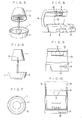
- FIGS. 1, 2 and 3 show an ashtray which is a first embodiment of the present invention and has an ash reception plate 1 and a base 2 therefor.
- the ash reception plate 1 constituting a large electrode is made of an electroconductive material such as a metal plate (large electrode) .
- Needle-like electrodes 3 constituting small electrodes are provided over the ash reception plate 1 at a distance therefrom and held by an arm 4 on the base 2.
- a high voltage from a high-voltage power supply 5 provided in the base 2 is applied between the ash reception plate 1 and the needle-like electrodes 3 through an insulated electric wire not shown in the drawings.
- FIG. 4 shows the high-voltage power supply 5 in which a DC voltage of 12 V is converted into a high-frequency signal by an oscillation circuit 6; the high-frequency signal is applied to the primary coil of a boosting transformer 8 through a feedback circuit 7; and an AC voltage of 5.0 kV from the secondary coil of the transformer 8 is rectified by a voltage doubler rectifier 9 to produce a DC output voltage of 6.5 kV, for example.
- a commercial AC voltage may be used instead of the DC voltage of 12 V.
- the AC voltage from the secondary coil of the boosting transformer 8 may be directly applied between the electrodes 1 and 3 instead of the DC output voltage of 6.5 kV.
- FIGS. 1, 2 and 3 Shown at 10 in FIGS. 1, 2 and 3 is a push-button power switch provided in a circuit through which the DC voltage of 12 V is applied to the oscillation circuit 6.
- a lamp inside the push button is lit so that it is possible to confirm by eyesight whether the switch 10 is turned on or off.
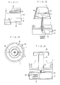
- FIGS. 5, 6 and 7 show an ashtray which is a second embodiment.
- a cover 11 constituting a large electrode made of an electroconductive material is provided so that the cover surrounds needle-like electrodes (small electrodes) 3.
- a high voltage is applied between the cover 11 and the needle-like electrodes 3 as in the first preferred embodiment.
- FIGS. 8, 9 and 10 show an ashtray which is a third preferred embodiment.
- a frame-like electrode 12 constituting an auxiliary electrode, whose cross section is oblong or circular, is provided beside needle-like electrodes 3 at a distance therefrom.
- a plate electrode 13 constituting a large electrode bent as U-shape or as arc is integrally coupled to the frame-like electrode 12 so that the flat or curved surface of the plate electrode 13 faces the side surface of an ash reception plate 1.
- a high voltage from a high-voltage power supply 5 provided in a base 2 is applied between the needle-like electrodes 3 and the frame-like electrode 12 or the plate electrode 13 through an insulated electric wire not shown in the drawings.
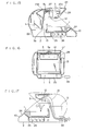
- FIG. 11 shows an ashtray which is a fourth embodiment.
- parallel plate electrodes 14 are provided as auxiliary electrodes at vertical distances from one another instead of the frame-like electrode 12 provided in the third preferred embodiment.
- the parallel plate electrodes 14 are hung by nonelectroconductive members (not shown in the drawings) from an arm 4 and connected to a plate electrode 13 through electroconductive members (not shown in the drawing). It is preferable to place needle-like electrodes 3 at the average height of the parallel plate electrodes 14. The same effect is produced by the fourth preferred embodiment as the above-described embodiments.
- FIGS. 12 and 13 show an ashtray which is a fifth preferred embodiment.
- an annular electrode 15 is provided as an auxiliary electrode to face needle-like electrodes 3 and located in the middle of a space surrounded by a cover 11 as in the second preferred embodiment.
- the annular electrode 15 is supported by electroconductive members 16 on the cover 11. The same effect is produced by the fifth embodiment as the above-described preferred embodiments.
- FIG. 14 shows an ashtray which is a sixth embodiment.
- a cylindrical member 17 extending upward through an ash reception plate 1 is provided.
- a cover 18 is provided over the cylindrical member 17 at a prescribed distance therefrom and covers the ash reception plate 1.
- Needle-like electrodes 3 are located under the cylindrical member 17 to face the interior thereof.
- a plate electrode 13 is located under the ash reception plate 1. The smoke of tobacco goes up from the ash reception plate 1 and is then transferred below the ash reception plate 1 through the cylindrical member 17 and caught on the plate electrode 13 by attraction.
- the needle-like electrodes 3 may be made up of either a single electrode or a plurality of electrodes spaced apart one another.
- the electrodes 3 may also be shaped as a ball, a rod, a spicule or saw teeth.
- the frame-like electrode 12 may be reticulate.
- the plate electrode 13 may have projections and recesses or be reticulate.
- an insulating ash reception plate 1 is mounted detachably on the bottom surface of a box-shaped base 2 having an upper opening, and a cover 23 comprising a horizontal plate 23a for closing the upper opening of said base 2 and a vertical plate 23b is pivoted rotatably on the rear portion of said box-shaped base 2 at the substantial central portion of said vertical plate 23b.
- a DC power supply 5 of several KV is fixed on the back of said vertical plate 23b, a cathode terminal 5a of the power supply 5 is provided on the lower surface of the horizontal plate 23a of said cover 23 and an anode terminal 5b is provided on the front surface of the vertical plate 23b.
- Guide plates 27 extending in the lower direction are formed at both sides of the horizontal plate 23a of said cover 23.
- An insulating guide plate 28 is engaged slidably with the cover 23 along the guide plates 27.
- a small electrode, such a needle-like electrode 3 is provided detachably on said insulating guide plate 28 so as to face the upper surface of said ash reception plate 1. So that a needle-like electrode 3 is brought into contact with said cathode electrode 5a of said power supply 5.
- An annular or rectangular frame electrode 12 is provided at a portion backwards of the needle-like electrode 3 on the intermediate lower surface of said guide plate 28 and a plate electrode 13 extending in the lower direction is connected to said annular frame electrode, so that in the state that the guide plate 28 is mounted on the opening and closing cover 23 said plate electrode 13 is brought into contact with the anode terminal 5b of said power supply 5 and faced to a side surface of said ash tray 1.
- an opening 22 communicating with an upper portion of said ash reception plate 1 is provided on a lower back portion of the base 2.
- a timer (not shown) is provided for maintaining ON state of a power switch 10 through a predetermined time, such as five minutes when the power switch 10 is turned on.
- the power switch 10 is automatically turned off after the predetermined time has passed.
- Reference numeral 24 denotes a lamp for indicating the ON state of the power switch 10, 25 a battery case and 26 batteries.
- such means may be provided that the power switch 10 is automatically turned on when said cover 23 is opened and turned off when said cover 23 is closed.
- a commercial AC voltage with AC adaptor 29 may be used instead of the DC voltage of 12V.
- Each of the above-described ashtrays provided in accordance with the present invention has a large advantage that the smoke of tobacco is efficiently attracted and caught without using a fan and expendables such as a filter.
Landscapes
- Disinfection, Sterilisation Or Deodorisation Of Air (AREA)
Applications Claiming Priority (4)
| Application Number | Priority Date | Filing Date | Title |
|---|---|---|---|
| JP4781987A JPS63102662A (ja) | 1986-06-20 | 1987-03-04 | 灰皿 |
| JP47819/87 | 1987-03-04 | ||
| JP62180917A JPS6431939A (en) | 1987-07-20 | 1987-07-20 | Production of metal composition having no dendride |
| JP180917/87 | 1987-11-30 |
Publications (1)
| Publication Number | Publication Date |
|---|---|
| EP0281414A1 true EP0281414A1 (de) | 1988-09-07 |
Family
ID=26388008
Family Applications (1)
| Application Number | Title | Priority Date | Filing Date |
|---|---|---|---|
| EP88301915A Withdrawn EP0281414A1 (de) | 1987-03-04 | 1988-03-04 | Aschenbecher |
Country Status (1)
| Country | Link |
|---|---|
| EP (1) | EP0281414A1 (de) |
Cited By (4)
| Publication number | Priority date | Publication date | Assignee | Title |
|---|---|---|---|---|
| WO1995017970A1 (en) * | 1993-12-29 | 1995-07-06 | Riccardo Briguglio | Electrostatic filter for tobacco ashes |
| WO2003009944A1 (en) * | 2001-07-16 | 2003-02-06 | Ragne Svadil | An air cleaner |
| CN103989253A (zh) * | 2014-05-29 | 2014-08-20 | 苏州乐聚一堂电子科技有限公司 | 无线感应烟灰缸 |
| CN105124760A (zh) * | 2015-08-08 | 2015-12-09 | 刘乐凝 | 一种带有烟雾消除器的烟灰缸 |
Citations (4)
| Publication number | Priority date | Publication date | Assignee | Title |
|---|---|---|---|---|
| DE2132410A1 (de) * | 1971-06-30 | 1973-01-18 | Bosch Gmbh Robert | Geraet zum reinigen von insbesondere tabakrauch enthaltender luft |
| US3807148A (en) * | 1972-03-13 | 1974-04-30 | N Fike | Air purifying device for use with an ash tray |
| US4177045A (en) * | 1978-07-10 | 1979-12-04 | Orel Jeannette V | Self-acting smoke sorbing device |
| FR2583657A1 (fr) * | 1985-06-20 | 1986-12-26 | Mingret Sa Ateliers R | Dispositif de nettoyage de l'air |
-
1988
- 1988-03-04 EP EP88301915A patent/EP0281414A1/de not_active Withdrawn
Patent Citations (4)
| Publication number | Priority date | Publication date | Assignee | Title |
|---|---|---|---|---|
| DE2132410A1 (de) * | 1971-06-30 | 1973-01-18 | Bosch Gmbh Robert | Geraet zum reinigen von insbesondere tabakrauch enthaltender luft |
| US3807148A (en) * | 1972-03-13 | 1974-04-30 | N Fike | Air purifying device for use with an ash tray |
| US4177045A (en) * | 1978-07-10 | 1979-12-04 | Orel Jeannette V | Self-acting smoke sorbing device |
| FR2583657A1 (fr) * | 1985-06-20 | 1986-12-26 | Mingret Sa Ateliers R | Dispositif de nettoyage de l'air |
Cited By (6)
| Publication number | Priority date | Publication date | Assignee | Title |
|---|---|---|---|---|
| WO1995017970A1 (en) * | 1993-12-29 | 1995-07-06 | Riccardo Briguglio | Electrostatic filter for tobacco ashes |
| WO2003009944A1 (en) * | 2001-07-16 | 2003-02-06 | Ragne Svadil | An air cleaner |
| US7048787B2 (en) | 2001-07-16 | 2006-05-23 | Ragne Svadil | Air cleaner |
| CN103989253A (zh) * | 2014-05-29 | 2014-08-20 | 苏州乐聚一堂电子科技有限公司 | 无线感应烟灰缸 |
| CN105124760A (zh) * | 2015-08-08 | 2015-12-09 | 刘乐凝 | 一种带有烟雾消除器的烟灰缸 |
| CN105124760B (zh) * | 2015-08-08 | 2019-01-18 | 刘乐凝 | 一种带有烟雾消除器的烟灰缸 |
Similar Documents
| Publication | Publication Date | Title |
|---|---|---|
| US4413364A (en) | Toilet light unit | |
| EP0341777A1 (de) | Anordnung zur Elektrokution von Insekten | |
| US5065272A (en) | Air ionizer | |
| US4549887A (en) | Electronic air filter | |
| US4790861A (en) | Ashtray | |
| US20060016333A1 (en) | Air conditioner device with removable driver electrodes | |
| US5446262A (en) | Soldering iron and soldering iron tip with spaced heatable shell member | |
| EP0084572A1 (de) | Elektrostatischer luftreiniger | |
| EP0731540B1 (de) | Ionengenerator für ein Gerät zum hermetischen Verbinden/Abschliessen von Kunststoffschläuchen | |
| CN100449892C (zh) | 离子发生单元 | |
| US2582330A (en) | Portable electric light with battery charging bracket | |
| US4828165A (en) | Ashtray | |
| EP0281414A1 (de) | Aschenbecher | |
| WO1988006397A3 (en) | Self contained gas discharge display device | |
| JPH0476622B2 (de) | ||
| US5926003A (en) | Battery charger | |
| US3912998A (en) | Battery charging, storing and dispensing device | |
| US20080028937A1 (en) | Air cleaner conductor system | |
| JPH0154034B2 (de) | ||
| US7821764B2 (en) | Voltage converter | |
| US1588464A (en) | Flash light | |
| JPH09289098A (ja) | 携帯型帯電除電器 | |
| SU993949A1 (ru) | Аэроионизатор | |
| RU4229U1 (ru) | Устройство для аэроионизации | |
| US2101902A (en) | Vibratory contact device |
Legal Events
| Date | Code | Title | Description |
|---|---|---|---|
| PUAI | Public reference made under article 153(3) epc to a published international application that has entered the european phase |
Free format text: ORIGINAL CODE: 0009012 |
|
| AK | Designated contracting states |
Kind code of ref document: A1 Designated state(s): DE FR GB IT |
|
| 17P | Request for examination filed |
Effective date: 19890209 |
|
| 17Q | First examination report despatched |
Effective date: 19901123 |
|
| STAA | Information on the status of an ep patent application or granted ep patent |
Free format text: STATUS: THE APPLICATION IS DEEMED TO BE WITHDRAWN |
|
| 18D | Application deemed to be withdrawn |
Effective date: 19910404 |