EP0281666A2 - Zentrifuge - Google Patents
Zentrifuge Download PDFInfo
- Publication number
- EP0281666A2 EP0281666A2 EP87113941A EP87113941A EP0281666A2 EP 0281666 A2 EP0281666 A2 EP 0281666A2 EP 87113941 A EP87113941 A EP 87113941A EP 87113941 A EP87113941 A EP 87113941A EP 0281666 A2 EP0281666 A2 EP 0281666A2
- Authority
- EP
- European Patent Office
- Prior art keywords
- intermediate sleeve
- shaft
- working head
- threaded element
- expansion part
- Prior art date
- Legal status (The legal status is an assumption and is not a legal conclusion. Google has not performed a legal analysis and makes no representation as to the accuracy of the status listed.)
- Granted
Links
Images

Classifications
-
- F—MECHANICAL ENGINEERING; LIGHTING; HEATING; WEAPONS; BLASTING
- F16—ENGINEERING ELEMENTS AND UNITS; GENERAL MEASURES FOR PRODUCING AND MAINTAINING EFFECTIVE FUNCTIONING OF MACHINES OR INSTALLATIONS; THERMAL INSULATION IN GENERAL
- F16D—COUPLINGS FOR TRANSMITTING ROTATION; CLUTCHES; BRAKES
- F16D1/00—Couplings for rigidly connecting two coaxial shafts or other movable machine elements
- F16D1/06—Couplings for rigidly connecting two coaxial shafts or other movable machine elements for attachment of a member on a shaft or on a shaft-end
- F16D1/08—Couplings for rigidly connecting two coaxial shafts or other movable machine elements for attachment of a member on a shaft or on a shaft-end with clamping hub; with hub and longitudinal key
- F16D1/09—Couplings for rigidly connecting two coaxial shafts or other movable machine elements for attachment of a member on a shaft or on a shaft-end with clamping hub; with hub and longitudinal key with radial clamping due to axial loading of at least one pair of conical surfaces
- F16D1/093—Couplings for rigidly connecting two coaxial shafts or other movable machine elements for attachment of a member on a shaft or on a shaft-end with clamping hub; with hub and longitudinal key with radial clamping due to axial loading of at least one pair of conical surfaces using one or more elastic segmented conical rings forming at least one of the conical surfaces, the rings being expanded or contracted to effect clamping
- F16D1/094—Couplings for rigidly connecting two coaxial shafts or other movable machine elements for attachment of a member on a shaft or on a shaft-end with clamping hub; with hub and longitudinal key with radial clamping due to axial loading of at least one pair of conical surfaces using one or more elastic segmented conical rings forming at least one of the conical surfaces, the rings being expanded or contracted to effect clamping using one or more pairs of elastic or segmented rings with mutually mating conical surfaces, one of the mating rings being contracted and the other being expanded
-
- B—PERFORMING OPERATIONS; TRANSPORTING
- B04—CENTRIFUGAL APPARATUS OR MACHINES FOR CARRYING-OUT PHYSICAL OR CHEMICAL PROCESSES
- B04B—CENTRIFUGES
- B04B9/00—Drives specially designed for centrifuges; Arrangement or disposition of transmission gearing; Suspending or balancing rotary bowls
- B04B9/08—Arrangement or disposition of transmission gearing ; Couplings; Brakes
- B04B2009/085—Locking means between drive shaft and rotor
Definitions
- the invention relates to a centrifuge with a working head placed on a shaft driven by a drive motor, in which a longitudinally slotted intermediate sleeve is arranged between the shaft and a central bore of the working head, which has a spreading part with an outer cone in the region of its upper end face facing away from the shaft threaded elements screwed to the end of the shaft are clamped against the bore.
- Such a centrifuge is known from DE-OS 25 01 513.
- a sleeve-shaped element that extends the drive shaft is placed on which the working head is placed.
- the upper part of this intermediate sleeve is slotted and is clamped against the central bore of the working head by an expansion cone via a screw axially screwed onto the shaft.
- a non-positive connection only occurs between the spreading intermediate sleeve and the working head in the lower area of the central bore, while the working head in the upper area of the bore is not specifically braced.
- the invention is based on the object of creating a secure, firm, play-free attachment between the working head and the shaft of a centrifuge even after prolonged use and frequent load changes, which on the other hand ensures easy detachability and is particularly suitable for small centrifuges.
- the shaft has a conical end
- the intermediate sleeve has a conical inner surface adapted to this end and that the threaded element has on its outer periphery projections against the inside of a stop surface of the intermediate sleeve on the one hand and against the tapered end of the expansion part on the other hand.
- a non-positive connection between the shaft or the intermediate sleeve and the working head is achieved both in the upper and in the lower area of the central hole.
- the non-positive connection in the lower area of the central bore takes place when the working head is placed on the shaft of the centrifuge, while the connection in the upper area of the working head is achieved by subsequently tightening the expansion part with the intermediate sleeve, which is pressed against the bore of the working head becomes. So that the intermediate sleeve can also expand radially, it has axial slots.
- the projections on the outer circumference of the threaded element are first pressed against the pointed end of the expansion part, so that this is released from engagement with the intermediate sleeve until the threaded element comes to rest with the stop surface of the intermediate sleeve and releases the intermediate sleeve from engagement with the conical end of the shaft.
- the non-positive clamping of the working head in the area of the upper and lower end of the central bore with the shaft ensures that the working head is held without play, even after a long number of load changes.
- This clamping system is also suitable for small centrifuges with a small shaft diameter, since only an intermediate sleeve is inserted between the shaft and the central bore of the working head, which can be kept very thin in its wall thickness.
- the projections of the threaded element are formed by an encircling flange which bears against an inwardly directed collar of the intermediate sleeve, this collar is preferably arranged at the end of the intermediate sleeve.
- a secure support of the working head on the shaft or the intermediate sleeve is ensured by a flange on the end of the intermediate sleeve facing the drive motor.
- the expansion part is preferably rotatably mounted on the threaded element, for which purpose a securing sleeve is arranged on the end of the threaded element and bears against an outer axial surface of the expanding part. A sliding ring can be inserted between this securing sleeve and the expansion part.
- the expansion part has at least one axial expansion slot, which is made in the region of the conical surfaces.
- the expansion part can consist of at least two shell-shaped parts, between which one or two slots remain when placed on the threaded element or the expansion part.
- expansion part With such a two-part or multi-part design of the expansion part, it is possible to place the expansion part on the threaded element without an appropriate securing sleeve, since then contact surfaces corresponding to the securing sleeve can already be formed on the threaded element. In order to reduce the friction between the projections of the threaded element and the stop surface of the intermediate sleeve, an inserted sliding ring is advantageous.
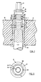
- an intermediate sleeve 3 is inserted in a central bore 1 of a working head 2, which in turn is placed on the end of the shaft 4 of a drive motor, not shown.
- the end 5 of the shaft 4, which extends into the central bore 1 or the intermediate sleeve 3, has a conical shape in the direction of the top side 6 of the working head 2.
- An extension 7 with an external thread 8 is attached to the end face of the shaft 4, on which a threaded element 9 is screwed.
- This threaded element 9 is a sleeve-shaped part 13, which in this exemplary embodiment extends with its free undulating end 14 through an intermediate sleeve 3.
- the upper end face of the intermediate sleeve 3 has an inwardly directed circumferential collar 10 with tapered surfaces 11 tapering towards the axis of the shaft 4.
- a securing sleeve 15 is placed on the wavy end 14 of the threaded element 9 and is fastened to the threaded element 9 with a pin 16.
- the free end of the threaded element 9 is provided with an external hexagon 17, via which the threaded element 9 can be rotated.
- projections 18 are formed, against which the collar 10 of the intermediate sleeve 3 bears.
- a slide ring 19 is inserted between the projections 18 and the collar 10;
- Another slide ring 20 is located between the axial upper side of the expansion part 12 and the lower axial surface of the securing sleeve 15.
- the working head 2 lies in the position shown in FIG. 1, in which it is firmly screwed to the shaft 4, on a circumferential flange 21 at the lower end of the intermediate sleeve 3.
- the threaded element 9 In order to release the working head 2 from the engagement with the shaft 4, as shown in FIG. 1, the threaded element 9 is rotated against the shaft 4 via the external hexagon 7, so that the projections 18 or the slide ring 19 resting thereon against the tapered end of the expansion part 12 and the underside of the collar 10 of the intermediate sleeve 3 comes to rest. With the rotation of the threaded element 9, the conical expansion part 12 is first released from engagement with the conical surface 11 of the collar 10 and when the Threaded element 9 moved in the axial direction, while at the same time the intermediate sleeve 3 is withdrawn from the conical end 5 of the shaft 4. This arrangement enables the working head 2 to be detached from the shaft 4 even if these parts are firmly wedged into one another.
- this arrangement has the advantage that, on the one hand, a contact between the shaft 4, the intermediate sleeve 3 and the working head 2 in the lower region of the working head 2 and, on the other hand, a contact between the end of the shaft 4, the sleeve-shaped part 13 of the threaded element 9 and the upper one Part of the intermediate sleeve 3 is ensured in the area of the top 6 of the working head 2.
- the intermediate sleeve 3 is first inserted from the bottom into the central bore 1 of the working head 2, so that the circumferential flange 21 comes to rest on the underside of the working head.
- the working head 2 thus prepared is then placed on the end 5 of the shaft 4 and the threaded element 9 is screwed with its sleeve-shaped part 13 to the shaft via the shaft-shaped end 14. With the screwing, the intermediate sleeve is first pulled over the shaft 4 until a non-positive connection is made in the lower region of the central bore 1 of the working head 2.
- the expansion part 12 is clamped against the conical surfaces of the collar 10 of the intermediate sleeve 3 via the lower radial surface of the securing sleeve 15, so that a positive connection is also achieved in the upper region of the central bore 1 of the working head 2.
- This connection provides a fixed mounting of the working head at least in the upper and lower area of the central bore 1.
- axial slots 23 are provided both from the lower end and from the upper end - three of these slots at each end in the embodiment shown.
Landscapes
- Engineering & Computer Science (AREA)
- General Engineering & Computer Science (AREA)
- Mechanical Engineering (AREA)
- Centrifugal Separators (AREA)
Abstract
Description
- Die Erfindung betrifft eine Zentrifuge mit einem auf eine von einem Antriebsmotor angetriebene Welle aufgesetzten Arbeitskopf, bei der zwischen der Welle und einer zentralen Bohrung des Arbeitskopfes eine längsgeschlitzte Zwischenhülse angeordnet ist, die über ein Spreizteil mit Außenkegel im Bereich ihrer der Welle abgewandten oberen Stirnseite über ein an dem Ende der Welle verschraubtes Gewindeelemente gegen die Bohrung verspannt ist.
- Eine derartige Zentrifuge ist aus der DE-OS 25 01 513 gekannt. Bei dieser Zentrifuge ist ein die Antriebswelle verlängerndes, hülsenförmiges Element aufgesetzt, auf das der Arbeitskopf aufgesetzt ist. Der obere Teil dieser Zwischenhülse ist geschlitzt ausgebildet und wird durch einen Spreizkegel über eine axial auf die Welle aufgeschraubte Schraube gegen die Zentralbohrung des Arbeitskopfes verspannt. Eine kraftschlüssige Verbindung kommt nur zwischen der gespreizten Zwischenhülse und dem Arbeitskopf im unteren Bereich der zentralen Bohrung zustande, während der Arbeitskopf im oberen Bereich der Bohrung nicht gezielt verspannt wird.
- Der Erfindunmg liegt die Aufgabe zugrunde, eine auch nach längerem Einsatz und häufigen Lastwechseln sichere, feste, spielfreie Befestigung zwischen dem Arbeitskopf und der Welle einer Zentrifuge zu schaffen, die andererseits eine leichte Lösbarkeit gewährleistet und insbesondere für kleine Zentrifugen geeignet ist.
- Diese Aufgabe wird dadurch gelöst, daß die Welle ein konisches Ende aufweist, die Zwischenhülse eine konische diesem Ende angepaßte Innenfläche besitzt und daß das Gewindeelement an seinem Außenumfang Vorsprünge aufweist, die gegen die Innenseite einer Anschlagfläche der Zwischenhülse einerseits und gegen das spitz zulaufende Ende des Spreizteiles andererseits anliegen.
- Durch die konische Ausbildung der Welle und die an den Konus der Welle angepaßte Innenfläche der Zwischenhülse einerseits und dem Spreizkegel am Ende der Welle bzw. der Zwischenhülse andererseits wird eine kraftschlüssige Verbindung zwischen der Welle bzw. der Zwischenhülse und dem Arbeitskopf sowohl im oberen als auch im unteren Bereich der zentralen Bohrung erzielt. Die kraftschlüssige Verbindung im unteren Bereich der zentralen Bohrung erfolgt bereits mit dem Aufsetzen des Arbeitskopfes auf die Welle der Zentrifuge, während die Verbindung im oberen Bereich des Arbeitskopfes durch das anschließende Verspannen des Spreizteiles mit der Zwischenhülse, die gegen die Bohrung des Arbeitskopfes gedrückt wird, erzielt wird. Damit sich auch die Zwischenhülse radial spreizen kann, weist sie axiale Schlitze auf. Um anschließend die miteinander verspannten Teile, beispielsweise beim wechseln eines Arbeitskopfes, wieder lösen zu können, werden die Vorsprünge am Außenumfang des Gewindeelementes zunächst gegen das spitzzulaufende Ende des Spreizteiles gedrückt, so daß dieses aus dem Eingriff mit der Zwischenhülse gelöst wird, bis dann das Gewindeelement zur Anlage mit der Anschlagfläche der Zwischenhülse gelangt und die Zwischenhülse aus dem Eingriff mit dem konischen Ende der Welle löst. Durch das kraftschlüssige Verspannen des Arbeitskopfes im Bereich des oberen und unteren Endes der zentralen Bohrung mit der Welle wird eine spielfreie Halterung des Arbeitskopfes, auch nach längeren Lastwechselzahlen, erzielt. Dieses Spannsystem eignet sich auch für kleine Zentrifugen mit kleinem Durchmesser der Welle, da zwischen der Welle und der zentralen Bohrung des Arbeitskopfes lediglich eine Zwischenhülse eingefügt wird, die in ihrer Wanddicke sehr gering gehalten werden kann.
- In einer vorteilhaften Ausgestaltung werden die Vorsprünge des Gewindeelementes durch einen umlaufenden Flansch gebildet der gegen einen nach innen gerichteten Kragen der Zwischenhülse anliegt, wobei dieser Kraggen bevorzugt am Ende der Zwischenhülse angeordnet ist. Durch diese Maßnahme ist in jeder Stellung des Gewindeelementes dessen umlaufender Flansch mit dem radialen umlaufenden Kragen der Zwischenhülse eingreift.
- Eine sichere Auflage des Arbeitskkopfes auf der Welle bzw. der Zwischenhülse wird durch einen Flansch an dem dem Antriebsmotor zugewandten Ende der Zwischenhülse gewährleistet.
- Das Spreizteil ist vorzugsweise an dem Gewindeelement drehbar gelagert, wozu auf das Ende des Gewindelementes eine Sicherungshülse angeordnet ist, die gegen eine äußere axiale Fkäche des Spreizteiles anliegt. Zwischen dieser Sicherungshülse und dem Spreizteil kann ein Gleitring eingesetzt sein. Um eine gute Anpassung des Spreizteiles an das Gewindeelement und die Zwischenhülse zu gewährleisten, weist das Spreizteil mindestens einen axialen Dehnungsschlitz, der im Bereich der konischen Flächen ausgeführt ist, auf. Aus dem gleichen Grund kann das Spreizteil aus mindestens zwei schalenförmigen Teilen bestehen, zwischen denen beim Anlegen an das Gewindeelement oder das Spreizteil ein oder zwei Schlitze verbleiben. Außerdem ist mit einer solchen zwei oder mehrteiligen Ausbildung des Spreizteiles ein Aufsetzen des Spreizteiles auf das Gewindeelement ohne eine entsprechende Sicherungshülse möglich, da dann der Sicherungshülse entsprechende Anlageflächen bereits an dem Gewindeelement ausgebildet sein können. Um die Reibung zwischen den Vorsprüngen des Gewindeelementes und der Anschlagfläche der Zwischenhülse zu verringern, ist ein eingefügter Gleitring von Vorteil.
- Ausführungsbeispiele der Erfindung sind in der Zeichnung dargestellt und werden nachstehend näher erläutert. Es zeigen
- Figur 1 eine Schnittdarstellung eines Arbeitskopfes im Bereich seiner zentralen Bohrung
- Figur 2 einen Schnitt entlang der Schnittlinie I-I in Figur 1 und
- Figur 3 eine Schnittdarstellung eines Arbeitskopfes mit gegenüber der Ausführungsform nach Figur 1 geänderter Verschraubung.
- Wie aus Figur 1 ersichtlich ist, ist in einer zentralen Bohrung 1 eines Arbeitskopfes 2 eine Zwischenhülse 3 eingesetzt, die ihrerseits auf das Ende der Welle 4 eines nicht dargestellten Antriebsmotors aufgesetzt ist. Das sich in die zentrale Bohrung 1 bzw. die Zwischenhülse 3 erstreckende Ende 5 der Welle 4 ist in Richtung der Oberseite 6 des Arbeitskopfes 2 konisch verlaufend ausgebildet. An der Stirnseite der Welle 4 ist ein Fortsatz 7 mit Außengewinde 8 angesetzt, auf dem ein Gewindeelement 9 aufgeschraubt ist. Bei diesem Gewindeelement 9 handelt es sich um ein hülsenförmiges Teil 13, das sich in diesem Ausführungsbeispiel mit seinem freien wellenförmigen Ende 14 durch eine Zwischenhülse 3 hindurch erstreckt. Die oberere Stirnseite der Zwischenhülse 3 besitzt einen nach innen gerichteten umlaufenden Kragen 10 mit zur Achse der Welle 4 hin abgeschrägt verlaufenden Kegelflächen 11. Gegen diese Kegelflächen 11 liegt ein konisches Spreizteil 12 an, das auf das wellenförmige Ende 14 des Gewindeelementes 9 aufgesteckt ist. Oberhalb des Spreizteiles 12 ist auf das wellenförmige Ende 14 des Gewindeelementes 9 eine Sicherungshülse 15 aufgesetzt, die mit einem Stift 16 an dem Gewindeelement 9 befestigt ist. Das freie Ende des Gewindeelementes 9 ist mit einem Außensechskant 17 versehen, über den das Gewindeelement 9 verdreht werden kann. Im Übergangsbereich zwischen dem hülsenförmigen Teil 13 und dem wellenförmigen Ende 14 des Gewindeelementes 9 sind in Folge der unterschiedlichen Außendurchmesser dieser Teile Vorsprünge 18 gebildet, gegen die der Kragen 10 der Zwischenhülse 3 anliegt. Zwischen den Vorsprüngen 18 und dem Kragen 10 ist ein Gleitring 19 eingefügt; ein weiterer Gleitring 20 befindet sich zwischen der axialen Oberseite des Spreizteiles 12 und der unteren axialen Fläche der Sicherungshülse 15. Der Arbeitskopf 2 liegt in der in Figur 1 gezeigten Stellung, in der er fest an der Welle 4 verschraubt ist, auf einem umlaufenden Flansch 21 am unteren Ende der Zwischenhülse 3 auf.
- Um den Arbeitskopf 2 aus dem Eingriff mit der Welle 4, wie dies in Figur 1 gezeigt ist, zu lösen, wird das Gewindeelement 9 über den Außensechskant 7 gegen die Welle 4 verdreht, so daß die Vorsprünge 18 bzw. der darauf aufliegende Gleitring 19 gegen das spitz zulaufende Ende des Spreizteiles 12 und die Unterseite des Kragens 10 der Zwischenhülse 3 zur Anlage kommt. Mit dem Verdrehen des Gewindeelementes 9 wird zunächst das konische Spreizteil 12 aus dem Eingriff mit der Kegelfläche 11 des Kragens 10 gelöst und beim weiteren Verdrehen des Gewindeelementes 9 in Achsrichtung verschoben, während gleichzeitig die Zwischenhülse 3 von dem konischen Ende 5 der Welle 4 abgezogen wird. Durch diese Anordnung ist ein Lösen des Arbeitskopfes 2 von der Welle 4 auch dann möglich, wenn diese Teile fest ineinander verkeilt sind. Weiterhin hat diese Anordnung den Vorteil, daß einerseits eine Anlage zwischen der Welle 4, der Zwischenhülse 3 und dem Arbeitskopf 2 im unteren Bereich des Arbeitskopfes 2 und andererseites eine Anlage zwischen dem Ende der Welle 4, dem hülsenförmigen Teil 13 des Gewindeelementes 9 und dem oberen Teil der Zwischenhülse 3 im Bereich der Oberseite 6 des Arbeitskopfes 2 gewährleistet ist.
- Zum Befestigen des Arbeitskopfes 2 wird zunächst die Zwischenhülse 3 von der Unterseite in die zentrale Bohrung 1 des Arbeitskopfes 2 eingesetzt, so daß der umlaufende Flansch 21 an der Unterseite des Arbeitskopfes zur Anlage gelangt. Anschließend wird der so vorbereitete Arbeitskopf 2 auf das Ende 5 der Welle 4 aufgesetzt und das Gewindeelement 9 mit seinem hülsenförmigen Teil 13 an der Welle über das wellenförmige Ende 14 verschraubt. Mit dem Verschrauben wird zunächst die Zwischenhülse über die Welle 4 gezogen, bis im unteren Bereich der zentralen Bohrung 1 des Arbeitskopfes 2 eine kraftschlüssige Verbindung hergestellt ist. Durch weiteres Verdrehen des Gewindeelementes 9 wird über die untere radiale Fläche der Sicherungshülse 15 das Spreitzteil 12 gegen die konischen Flächen des Kragens 10 der Zwischenhülse 3 vespannt, so daß auch im oberen Bereich der zentralen Bohrung 1 des Arbeitskopfes 2 eine kraftschlüssige Verbindung erzielt wird. Durch diese Verbindung ist eine feste Lagerung des Arbeitskopfes zumindest im oberen und unteren Bereich der zentralen Bohrung 1 gegeben.
- Trotz der Verkeilung der einzelnen Bauteile miteinander ist ein anschließendes Lösen des Arbeitskopfes über das Gewindeelement 9 ohne großen Kraftaufwand möglich.
- Während bei der Ausführungsform nach Figur 1 das Gewindeelement 9 auf das Außengewinde 8 der Welle 4 aufgeschraubt ist, ist bei der ansonsten baugleichen Ausführungsform nach Figur 3 das Gewindeelement 9 in ein Innengewinde 22 der Welle 4 eingeschraubt.
- Um ein Spreizen der Zwischenhülse 3 zu ermöglichen, sind sowohl vom unteren Ende ausgehend als auch vom oberen Ende aus axiale Schlitze 23 - in der gezeigten Ausführung drei dieser Schlitze an jedem Ende - vorhanden.
Claims (8)
Applications Claiming Priority (2)
| Application Number | Priority Date | Filing Date | Title |
|---|---|---|---|
| DE19873708136 DE3708136C1 (de) | 1987-03-13 | 1987-03-13 | Zentrifuge |
| DE3708136 | 1987-03-13 |
Publications (3)
| Publication Number | Publication Date |
|---|---|
| EP0281666A2 true EP0281666A2 (de) | 1988-09-14 |
| EP0281666A3 EP0281666A3 (en) | 1989-07-26 |
| EP0281666B1 EP0281666B1 (de) | 1991-11-13 |
Family
ID=6322963
Family Applications (1)
| Application Number | Title | Priority Date | Filing Date |
|---|---|---|---|
| EP19870113941 Expired - Lifetime EP0281666B1 (de) | 1987-03-13 | 1987-09-24 | Zentrifuge |
Country Status (2)
| Country | Link |
|---|---|
| EP (1) | EP0281666B1 (de) |
| DE (2) | DE3708136C1 (de) |
Cited By (3)
| Publication number | Priority date | Publication date | Assignee | Title |
|---|---|---|---|---|
| US5362293A (en) * | 1992-12-14 | 1994-11-08 | E. I. Du Pont De Nemours And Company | Drive clutch for a centrifuge rotor |
| DE102014112501A1 (de) * | 2014-08-29 | 2016-03-03 | Andreas Hettich Gmbh & Co. Kg | Zentrifuge |
| CN114650885A (zh) * | 2019-11-22 | 2022-06-21 | 阿法拉伐股份有限公司 | 用于使分离盘的堆叠安装在离心分离器筒中的方法和工具 |
Families Citing this family (1)
| Publication number | Priority date | Publication date | Assignee | Title |
|---|---|---|---|---|
| DE202004001679U1 (de) | 2004-02-04 | 2005-06-16 | Joh. Winklhofer & Söhne GmbH und Co. KG | Spann- oder Führungsschiene mit Installationskanal |
Family Cites Families (5)
| Publication number | Priority date | Publication date | Assignee | Title |
|---|---|---|---|---|
| US2613968A (en) * | 1949-07-13 | 1952-10-14 | Int Harvester Co | Drive coupling for centrifugal separators |
| GB1447465A (en) * | 1973-03-20 | 1976-08-25 | Int Equipment Co | Centrifuge equipment |
| DE2501513A1 (de) * | 1975-01-16 | 1976-07-22 | Christ Jun Martin | Vorrichtung zur loesbaren verbindung des arbeitskopfs einer laborzentrifuge mit der abtriebswelle des antriebsmotors |
| US4202644A (en) * | 1978-07-10 | 1980-05-13 | Trantorque Corporation | Mounting device |
| US4456396A (en) * | 1982-01-06 | 1984-06-26 | Elliott Turbomachinery Company, Inc. | Coupling and method of assembly and disassembly |
-
1987
- 1987-03-13 DE DE19873708136 patent/DE3708136C1/de not_active Expired
- 1987-09-24 EP EP19870113941 patent/EP0281666B1/de not_active Expired - Lifetime
- 1987-09-24 DE DE8787113941T patent/DE3774566D1/de not_active Expired - Lifetime
Cited By (6)
| Publication number | Priority date | Publication date | Assignee | Title |
|---|---|---|---|---|
| US5362293A (en) * | 1992-12-14 | 1994-11-08 | E. I. Du Pont De Nemours And Company | Drive clutch for a centrifuge rotor |
| DE102014112501A1 (de) * | 2014-08-29 | 2016-03-03 | Andreas Hettich Gmbh & Co. Kg | Zentrifuge |
| DE102014112501B4 (de) * | 2014-08-29 | 2017-07-27 | Andreas Hettich Gmbh & Co. Kg | Zentrifuge |
| CN114650885A (zh) * | 2019-11-22 | 2022-06-21 | 阿法拉伐股份有限公司 | 用于使分离盘的堆叠安装在离心分离器筒中的方法和工具 |
| CN114650885B (zh) * | 2019-11-22 | 2023-10-03 | 阿法拉伐股份有限公司 | 用于使分离盘的堆叠安装在离心分离器筒中的方法和工具 |
| US12320381B2 (en) | 2019-11-22 | 2025-06-03 | Alfa Laval Corporate Ab | Method for mounting a stack of separating discs in a centrifugal separator bowl and a tool |
Also Published As
| Publication number | Publication date |
|---|---|
| DE3774566D1 (de) | 1991-12-19 |
| EP0281666B1 (de) | 1991-11-13 |
| DE3708136C1 (de) | 1988-03-03 |
| EP0281666A3 (en) | 1989-07-26 |
Similar Documents
| Publication | Publication Date | Title |
|---|---|---|
| DE2932538C2 (de) | ||
| DE4332485C1 (de) | Vorrichtung zum Verbinden eines kerbverzahnten, der Übertragung von Drehmomenten dienenden Wellenzapfens | |
| DE69011330T2 (de) | Anordnung zur verriegelung einer welle zu einem maschinenteil. | |
| DE2734784B1 (de) | Spannsatz | |
| DE1295285B (de) | Anschlag- und Festhaltescheibe fuer ein Maschinenteil in einer Bohrung oder auf einer Welle | |
| EP0281666B1 (de) | Zentrifuge | |
| DE68926336T2 (de) | Bolzeneinrichtung | |
| AT2954U1 (de) | Schnellmontagetopf für möbelscharniere | |
| EP0236551B1 (de) | Zentrifuge | |
| DE1480574B1 (de) | Lenkzapfen fuer die lenkbaren Vorderraeder von Kraftfahrzeugen | |
| DE8308038U1 (de) | Lenksaeule mit einstellbar daran befestigtem lenkrad | |
| EP0208095B1 (de) | Vorrichtung zum Befestigen eines Gabelbaums an dem Mast eines Segelbretts | |
| DE3418993C2 (de) | Innenspannsatz | |
| DE29702673U1 (de) | Federspanner zum Spannen von Schraubenfedern mit zwei Druckplatten | |
| EP0145795A1 (de) | Lenkrolle mit einer Halterung zu ihrer lösbaren Befestigung | |
| DE1779009A1 (de) | Lenkrollenbefestigung an Moebelfuessen u.dgl. | |
| DE2621702A1 (de) | Spreizbarer dorn | |
| DE2461465C3 (de) | Einrichtung zum Aufspannen von Autorädern unterschiedlicher Felgenausführung auf einem Wellenende einer Auswuchtmaschine | |
| DE2200540B2 (de) | Einrichtung zur Tempierung eines Geschoßzeitzünders | |
| DE8602006U1 (de) | Montagevorrichtung für konzentrisch zusammen zu fügende Bauteile, insbesondere für Scheibenkupplungen von Kraftfahrzeuggetrieben | |
| DE4339978A1 (de) | Welle-/Nabe-Verbindung | |
| DE69711358T2 (de) | Vorrichtung zur Halterung einer Schraube auf einer Unterlage | |
| DE3517410A1 (de) | Vorrichtung zum festlegen loesbar verbindbarer teile | |
| DE2025283A1 (de) | Skistiefel | |
| DE3406685A1 (de) | Lenkrolle mit einer halterung zu ihrer loesbaren befestigung |
Legal Events
| Date | Code | Title | Description |
|---|---|---|---|
| PUAI | Public reference made under article 153(3) epc to a published international application that has entered the european phase |
Free format text: ORIGINAL CODE: 0009012 |
|
| 17P | Request for examination filed |
Effective date: 19871002 |
|
| AK | Designated contracting states |
Kind code of ref document: A2 Designated state(s): DE FR GB |
|
| PUAL | Search report despatched |
Free format text: ORIGINAL CODE: 0009013 |
|
| AK | Designated contracting states |
Kind code of ref document: A3 Designated state(s): DE FR GB |
|
| 17Q | First examination report despatched |
Effective date: 19900912 |
|
| GRAA | (expected) grant |
Free format text: ORIGINAL CODE: 0009210 |
|
| AK | Designated contracting states |
Kind code of ref document: B1 Designated state(s): DE FR GB |
|
| REF | Corresponds to: |
Ref document number: 3774566 Country of ref document: DE Date of ref document: 19911219 |
|
| GBT | Gb: translation of ep patent filed (gb section 77(6)(a)/1977) | ||
| ET | Fr: translation filed | ||
| PLBE | No opposition filed within time limit |
Free format text: ORIGINAL CODE: 0009261 |
|
| STAA | Information on the status of an ep patent application or granted ep patent |
Free format text: STATUS: NO OPPOSITION FILED WITHIN TIME LIMIT |
|
| 26N | No opposition filed | ||
| REG | Reference to a national code |
Ref country code: GB Ref legal event code: 732E |
|
| REG | Reference to a national code |
Ref country code: FR Ref legal event code: TP |
|
| REG | Reference to a national code |
Ref country code: GB Ref legal event code: 732E |
|
| REG | Reference to a national code |
Ref country code: FR Ref legal event code: TP |
|
| PGFP | Annual fee paid to national office [announced via postgrant information from national office to epo] |
Ref country code: GB Payment date: 19980827 Year of fee payment: 12 |
|
| PGFP | Annual fee paid to national office [announced via postgrant information from national office to epo] |
Ref country code: DE Payment date: 19980901 Year of fee payment: 12 |
|
| PGFP | Annual fee paid to national office [announced via postgrant information from national office to epo] |
Ref country code: FR Payment date: 19980930 Year of fee payment: 12 |
|
| REG | Reference to a national code |
Ref country code: GB Ref legal event code: 732E |
|
| PG25 | Lapsed in a contracting state [announced via postgrant information from national office to epo] |
Ref country code: GB Free format text: LAPSE BECAUSE OF NON-PAYMENT OF DUE FEES Effective date: 19990924 |
|
| GBPC | Gb: european patent ceased through non-payment of renewal fee |
Effective date: 19990924 |
|
| PG25 | Lapsed in a contracting state [announced via postgrant information from national office to epo] |
Ref country code: FR Free format text: LAPSE BECAUSE OF NON-PAYMENT OF DUE FEES Effective date: 20000531 |
|
| PG25 | Lapsed in a contracting state [announced via postgrant information from national office to epo] |
Ref country code: DE Free format text: LAPSE BECAUSE OF NON-PAYMENT OF DUE FEES Effective date: 20000701 |
|
| REG | Reference to a national code |
Ref country code: FR Ref legal event code: ST |