EP0281690A1 - Ecran de projection par l'arrière et système de projection pourvu d'un tel système - Google Patents
Ecran de projection par l'arrière et système de projection pourvu d'un tel système Download PDFInfo
- Publication number
- EP0281690A1 EP0281690A1 EP87202649A EP87202649A EP0281690A1 EP 0281690 A1 EP0281690 A1 EP 0281690A1 EP 87202649 A EP87202649 A EP 87202649A EP 87202649 A EP87202649 A EP 87202649A EP 0281690 A1 EP0281690 A1 EP 0281690A1
- Authority
- EP
- European Patent Office
- Prior art keywords
- light
- rear projection
- screen
- projection screen
- elements
- Prior art date
- Legal status (The legal status is an assumption and is not a legal conclusion. Google has not performed a legal analysis and makes no representation as to the accuracy of the status listed.)
- Withdrawn
Links
- 238000003892 spreading Methods 0.000 claims abstract description 42
- 230000003667 anti-reflective effect Effects 0.000 claims description 4
- 230000005540 biological transmission Effects 0.000 claims description 3
- 230000004304 visual acuity Effects 0.000 abstract description 8
- 238000009826 distribution Methods 0.000 description 7
- 239000000463 material Substances 0.000 description 5
- 230000001419 dependent effect Effects 0.000 description 3
- 230000000694 effects Effects 0.000 description 3
- 238000007689 inspection Methods 0.000 description 3
- 229920003229 poly(methyl methacrylate) Polymers 0.000 description 3
- 239000004926 polymethyl methacrylate Substances 0.000 description 3
- 238000007788 roughening Methods 0.000 description 2
- 239000011358 absorbing material Substances 0.000 description 1
- 239000006117 anti-reflective coating Substances 0.000 description 1
- 230000002238 attenuated effect Effects 0.000 description 1
- 239000011248 coating agent Substances 0.000 description 1
- 238000000576 coating method Methods 0.000 description 1
- 230000003247 decreasing effect Effects 0.000 description 1
- 239000006185 dispersion Substances 0.000 description 1
- 238000003384 imaging method Methods 0.000 description 1
- 239000012535 impurity Substances 0.000 description 1
- 238000007373 indentation Methods 0.000 description 1
- 238000004519 manufacturing process Methods 0.000 description 1
- 238000000034 method Methods 0.000 description 1
- 230000003287 optical effect Effects 0.000 description 1
- 210000001747 pupil Anatomy 0.000 description 1
Images


Classifications
-
- G—PHYSICS
- G03—PHOTOGRAPHY; CINEMATOGRAPHY; ANALOGOUS TECHNIQUES USING WAVES OTHER THAN OPTICAL WAVES; ELECTROGRAPHY; HOLOGRAPHY
- G03B—APPARATUS OR ARRANGEMENTS FOR TAKING PHOTOGRAPHS OR FOR PROJECTING OR VIEWING THEM; APPARATUS OR ARRANGEMENTS EMPLOYING ANALOGOUS TECHNIQUES USING WAVES OTHER THAN OPTICAL WAVES; ACCESSORIES THEREFOR
- G03B21/00—Projectors or projection-type viewers; Accessories therefor
- G03B21/54—Accessories
- G03B21/56—Projection screens
- G03B21/60—Projection screens characterised by the nature of the surface
- G03B21/62—Translucent screens
- G03B21/625—Lenticular translucent screens
Definitions
- the invention relates to a rear projection screen having a front and a rear side for displaying on the front side of the screen an image supplied by at least one primary image source placed on the rear side of the screen, said screen comprising a light-transparent plate having on its front side a multiple of parallel-arranged first light-spreading elements extending in a first direction across the plate for spreading light in a first plane perpendicular to the first direction, said elements having steep edges for obtaining total internal reflection and a tip having a curved flatter portion for transmission and refraction.
- the invention also relates to a rear projection system provided with such a rear projection screen.
- Rear projection screens are used in various types of display systems such as radar screens, flight and ship simulators, microfilm readers and rear projection systems for video and cinematographic pictures.
- display systems such as radar screens, flight and ship simulators, microfilm readers and rear projection systems for video and cinematographic pictures.
- an image is generated in a primary image source and is imaged on the rear projection screen by a system of projection lenses.
- the projection screen spreads the light incident from the rear into the audience space in front of the screen.
- Projection systems for the display of colour video programmes comprise three primary image sources for red, green and blue, respectively, which are projected onto the screen by separate systems of projection lenses.
- the light intensity of each image source is maximum on the optical axis of the relevant image source and the associated system of projection lenses. Since the three image sources are placed side by side or above one another, the said axes extend at angles at the area of the projection screen so that without any further steps, the viewer observes a colour shift dependent on his position in the audience space.
- This is achieved by providing light spreading elements with a height-to-width ratio of at least 1:1 extending in the vertical direction, whose tip has a width of at most half the width at the base and in which the tip has a specially shaped indentication.
- the height of the element is herein to be understood to mean the maximum relief perpendicular to the plane of the screen.
- Light-absorbing material can be provided in the deep grooves between the elements so that reflection of ambient light is inhibited by the screen and the contrast in the displayed image is increased.
- the light from the primary image source, and incident on the rear side of the screen, is guided to the tips of the profile due to total internal reflection on the steep edges so that there is a high transmission for this light. Due to the combination of steep edges and curved flatter tips a wide angular distribution in the horizontal direction is also achieved.
- the elements extending in the vertical direction spread the light entering via the rear side in a horizontal direction in a region extending over approximately 85° to the left and right.
- the light-spreading elements do not have any appreciable effect, so that other steps are to be taken for spreading light in that direction.
- the said steps to spread the light in the vertical direction have two drawbacks. In the first place they limit the resolving power of the screen because the imaging beams traverse, as it were, a "misty" screen and are therefore no longer imaged sharply on the front side of the screen viewed by the audience. In the second place this misty, approximately Gaussian light spread results in a considerable portion of the light-falling outside the audience space. This is of course at the expense of the light intensity within the audience room.
- the invention has for its object to obviate these drawbacks.
- a rear projection screen is characterized in that the rear side of the plate has parallel-arranged second light-spreading elements extending in a second direction substantially perpendicular to the first direction for spreading light in a second plane perpendicular to the second direction.
- the horizontal spread is substantially only determined by the elements on the front side. Since there is no longer any, or considerably less light dispersion required in the screen, the picture is projected sharply.
- the shape of the light-spreading elements on the rear side may be adapted to the intensity distribution in the vertical direction desired for a given field of application. It stands to reason that the invention can also be used for a tip which has a different shape than that described in the said European Patent Application No. 0,148,529.
- the rear projection screen according to the invention is preferably characterized in that light, which is substantially perpendicularly incident on the rear side of the screen, is refracted through an angle of between 5° and 20° at a maximum by the second light-spreading elements, in co-operation with the first light-spreading elements which are not curved in the vertical direction.
- the full vertical dimension of the audience room is then approximately 10° to approximately 40°.
- the desired value is dependent on the field of application.
- a total vertical viewing angle of approximately 22° is optimal.
- the rear projection screen according to the invention may also be characterized in that the maximum angle between the surface of the second light-spreading elements and the plane of the plate has a value of between approximately 10° and approximately 40°.
- the commonly used materials for a projection screen such as polymethylmethacrylate (PMMA), have a refractive index n of approximately 1.5.
- the said geometrical angles of approximately 10° and approximately 40° result in the above-mentioned approximately vertical viewing angles at this value of n.
- a first embodiment of the rear projection screen according to the invention is characterized in that the second light-spreading elements are convex elements.
- a further embodiment is, however, characterized in that the second light-spreading elements are concave elements.
- a third embodiment of the rear projection screen according to the invention is characterized in that a number of the second light-spreading elements is convex and a number is concave. This embodiment may be further characterized in that the convex and concave second light-spreading elements alternate with one another.
- a preferred embodiment of the rear projection screen according to the invention is characterized in that the cross-sections of the second light-spreading elements substantially have the shape of a segment of a circle. This shape results in a substantially rectangular intensity distribution and can be manufactured in a relatively simple manner.
- the rear projection screen according to the invention may be further characterized in that a segment of a circle constitutes an arc of approximately 44°. With this arc a full vertical viewing angle of 22° which is very suitable for projection television system is obtained.
- the rear projection screen according to the invention is further characterized in that a diffusor is provided in the plate.
- the rear projection screen according to the invention may be characterized in that the rear side of the plate is anti-reflective. This reduces both the loss of light from the primary picture source due to reflection on the rear side of the plate, and it reduces reflection of ambient light entering through the front side of the plate.
- a preferred embodiment of the rear projection screen according to the invention is further characterized in that the number of second light-spreading elements is at least 2000.
- the width of a light-spreading element is smaller than the detail size of the projected image so that there is no loss of resolving power in the screen.
- the invention also relates to a rear projection system comprising a primary image source and a system of lenses for projecting the image generated by the primary image source onto a screen, which system is provided with a rear projection screen in accordance with any one of the above-mentioned embodiments.
- the intensity distribution in the vertical direction and the resolving power of such a rear projection system are better than in a system having the known rear projection screen.
- Figure 1 is a diagrammatic horizontal cross-section of a rear projection screen for the display of a colour video programme which system has a known rear projection screen.
- the reference numerals 11, 12 and 13 denote three primary image sources, for example cathode ray tubes which generate the red, green or blue component of a colour video image on their respective windows 14, 15 and 16.
- the image components thus formed are projected onto the projection screen 30 by the systems of projection lenses 21, 22 and 23 diagrammatically shown as single lenses in the Figure.
- the screen shown comprises two plates.
- the rear plate 31 has a Fresnel structure so that the pupils of the projection lens systems are imaged in the audience room.
- the front plate 40 has elements 41 on its front side, which elements spread the light in the plane of the drawing, i.e. the horizontal plane. These elements extend throughout the height of the screen at right angles to the plane of the drawing. The elements whose tips have an indentation have very good properties relating to the horizontal light-spreading and the colour shift in that plane.
- Such a structure in which the height D is at least equal to half the width B is described in the European Patent Application No 0,148,529 laid open to public inspection.
- the light spread perpendicular to the plane of the drawing, i.e. in the vertical direction, in the screen shown is the result of a large number of transparent grains 42 incorporated for that purpose in the front plate, which grains have a refractive index which is different from the refractive index of the plate material.
- a roughened surface on the rear side of the plane may serve for the same purpose.
- a plate having a roughened surface or being provided with light-dispersing properties in another manner has the drawback of a decreasing resolving power of the screen. This drawback is considerably reduced in the projection screen according to the invention.
- Figure 2 part of a plate according to the invention for a rear projection screen is shown in a vertical cross-section.
- One of the light-spreading elements present on the front side of the plate in the horizontal direction is again denoted by the reference numeral 41.
- Second light-spreading elements 43 which reflect the light incident thereon in the vertical direction are provided on the rear side of the plate.
- the ratios shown on the radii of curvature and the width are associated with a plate which is eminently suitable for use in a projection television system or a video monitor.
- the angle ⁇ between the normal on the surface of an element and the normal on the plane of the plate is approximately 22° and consequently the angle ⁇ which is enclosed between the surfaces of two juxtaposed elements is approximately 136°.
- the screen is manufactured of a material having a refractive index of approximately 1.5, such as PMMA, this results in co-operation with the front side which is not curved in the vertical direction, in a vertical viewing angle of approximately 22°.
- the width p of an element is, for example 200 ⁇ m. This value is approximately equal to the resolving power of the human eye and at a screen height of approximately one meter it is considerably smaller than the detail size of a video image projected thereon, which comprises a number of lines of the order of 1000.
- Figure 3 shows a further embodiment of the plate, likewise in a vertical cross-section. Unlike Figure 2 in which the light-spreading elements on the outside were convex, the light-spreading elements 43 are concave on the outside.
- the values of the angles ⁇ and ⁇ and of the width p may be equal to those of the plate shown in Figure 2 when this plate is used in a projection television system.
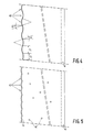
- Figure 4 shows a third embodiment of the plate in a vertical cross-section.
- the light-dispersing elements 43 are alternately convex and concave and pass into one another.
- the widths P1 and p2 of the convex and concave elements may be equal or unequal, respectively.
- Figure 5 shows some steps which can be taken in connection with the invention.
- a small quantity of light-dispersing grains may be provided, for example at most one third of the quantity in the known screen.
- This "bulk diffusor" results in too abrupt intensity variations, for example due to inaccuracies in the shape of the light-spreading elements 41 and 43, being attenuated so that an intensity distribution is obtained which is pleasant to the eye.
- the rear side may be made anti-reflective. This can be realized, for example by providing a conventional single or multilayer anti-reflective coating on the rear side, but also by providing the rear side with a fine roughening and providing a layer of consant thickness thereon as described in European Patent Application No. 0,131,341. It is alternatively possible to provide the rear side with a microrelief structure which is commonly referred to as "moth's eye structure" and is described, for example in the magazine “Optica Acta", Vol. 29, No. 7, pages 993-1009.
- the resolving power is improved considerably.
- the way in which this improvement results in an improvement of the resolving power in the horizontal and vertical directions depends on the position of the image of the primary image source formed by the projection lens system with respect to the front and rear sides of the plate.
- a factor 2 in the horizontal direction and simultaneously a factor 4/3 in the vertical direction has been found to be attainable in practice.
Landscapes
- Physics & Mathematics (AREA)
- General Physics & Mathematics (AREA)
- Overhead Projectors And Projection Screens (AREA)
- Transforming Electric Information Into Light Information (AREA)
- Video Image Reproduction Devices For Color Tv Systems (AREA)
- Projection Apparatus (AREA)
Applications Claiming Priority (2)
| Application Number | Priority Date | Filing Date | Title |
|---|---|---|---|
| NL8700135 | 1987-01-21 | ||
| NL8700135A NL8700135A (nl) | 1987-01-21 | 1987-01-21 | Doorzichtprojektiescherm en doorzichtprojektiesysteem voorzien van een dergelijk scherm. |
Publications (1)
| Publication Number | Publication Date |
|---|---|
| EP0281690A1 true EP0281690A1 (fr) | 1988-09-14 |
Family
ID=19849446
Family Applications (1)
| Application Number | Title | Priority Date | Filing Date |
|---|---|---|---|
| EP87202649A Withdrawn EP0281690A1 (fr) | 1987-01-21 | 1987-12-30 | Ecran de projection par l'arrière et système de projection pourvu d'un tel système |
Country Status (8)
| Country | Link |
|---|---|
| US (1) | US4762393A (fr) |
| EP (1) | EP0281690A1 (fr) |
| JP (1) | JPH01185539A (fr) |
| CN (1) | CN1008949B (fr) |
| AU (1) | AU603963B2 (fr) |
| CA (1) | CA1298501C (fr) |
| DK (1) | DK19888A (fr) |
| NL (1) | NL8700135A (fr) |
Cited By (3)
| Publication number | Priority date | Publication date | Assignee | Title |
|---|---|---|---|---|
| EP0414313A1 (fr) * | 1989-08-22 | 1991-02-27 | Koninklijke Philips Electronics N.V. | Ecran de projection par transparence et système de projection par transparence muni d'un tel écran |
| EP0542548A3 (en) * | 1991-11-15 | 1993-09-22 | Matsushita Electric Industrial Co., Ltd | Transmission type screen and method of manufacturing thereof |
| BE1015771A3 (nl) * | 2003-11-06 | 2005-08-02 | Kantoorinrichting Stulens N V | Doorzichtscherm. |
Families Citing this family (21)
| Publication number | Priority date | Publication date | Assignee | Title |
|---|---|---|---|---|
| US5400114A (en) * | 1991-09-05 | 1995-03-21 | Hitachi, Ltd. | Rear-projection screen and a rear projection image display employing the rear-projection screen |
| US5594561A (en) * | 1993-03-31 | 1997-01-14 | Palomar Technologies Corporation | Flat panel display with elliptical diffuser and fiber optic plate |
| US5706062A (en) * | 1993-06-20 | 1998-01-06 | Unic View Ltd. | Projector system including keystone correction |
| US5617152A (en) * | 1993-06-20 | 1997-04-01 | Unic View Ltd. | Projector system for video and computer generated information |
| US5481385A (en) * | 1993-07-01 | 1996-01-02 | Alliedsignal Inc. | Direct view display device with array of tapered waveguide on viewer side |
| US5521726A (en) * | 1994-08-26 | 1996-05-28 | Alliedsignal Inc. | Polarizer with an array of tapered waveguides |
| US5657408A (en) * | 1994-12-23 | 1997-08-12 | Alliedsignal Inc. | Optical device comprising a plurality of units having at least two geometrically-differentiated tapered optical waveguides therein |
| US6969635B2 (en) | 2000-12-07 | 2005-11-29 | Reflectivity, Inc. | Methods for depositing, releasing and packaging micro-electromechanical devices on wafer substrates |
| US5796499A (en) * | 1997-02-28 | 1998-08-18 | Polaroid Corporation | Transmission holographic diffuser made and used to effect lateral color constancy in rear screen projection display systems |
| US5999281A (en) * | 1997-02-28 | 1999-12-07 | Polaroid Corporation | Holographic projection screen combining an elliptical holographic diffuser and a cylindrical light-collimator |
| US6600599B2 (en) | 1998-06-09 | 2003-07-29 | Avery Dennison Corporation | Rear projection screens and light filters with conformable coatings and methods of making the same |
| US6962419B2 (en) | 1998-09-24 | 2005-11-08 | Reflectivity, Inc | Micromirror elements, package for the micromirror elements, and projection system therefor |
| DE10082052T1 (de) * | 1999-07-02 | 2001-09-27 | Thomson Licensing Sa | Fernseh-Projektionsschirm |
| US6466368B1 (en) | 2000-04-26 | 2002-10-15 | 3M Innovative Properties Company | Rear projection screen with reduced speckle |
| US7300162B2 (en) * | 2000-08-30 | 2007-11-27 | Texas Instruments Incorporated | Projection display |
| US7023606B2 (en) * | 2001-08-03 | 2006-04-04 | Reflectivity, Inc | Micromirror array for projection TV |
| KR100467614B1 (ko) * | 2002-10-15 | 2005-01-24 | 삼성전자주식회사 | 배면 투사 스크린 및 이를 채용한 프로젝터 |
| KR100753340B1 (ko) * | 2002-10-21 | 2007-08-30 | 최해용 | 전,후 양면 시청용 필름 스크린 |
| US7042622B2 (en) | 2003-10-30 | 2006-05-09 | Reflectivity, Inc | Micromirror and post arrangements on substrates |
| US20070253058A1 (en) * | 2006-05-01 | 2007-11-01 | Bright View Technologies, Inc. | Brightness enhancement structures including optical microstructures to provide elliptical diffusion patterns and methods of fabricating and operating the same |
| JP2012128137A (ja) * | 2010-12-15 | 2012-07-05 | Seiko Epson Corp | 反射型スクリーンおよび反射型スクリーンの製造方法 |
Citations (6)
| Publication number | Priority date | Publication date | Assignee | Title |
|---|---|---|---|---|
| US4053208A (en) * | 1975-02-03 | 1977-10-11 | Fuji Photo Film Co., Ltd. | Rear projection screens |
| US4147408A (en) * | 1976-12-23 | 1979-04-03 | Polaroid Corporation | Back projection viewing screen |
| GB2072376A (en) * | 1980-01-29 | 1981-09-30 | Matsushita Electric Industrial Co Ltd | Translucent projection screen |
| WO1982004518A1 (fr) * | 1981-06-18 | 1982-12-23 | Luis W Alvarez | Dispositif de vision pour television |
| EP0131341A1 (fr) | 1983-07-11 | 1985-01-16 | Koninklijke Philips Electronics N.V. | Méthode de réduction des réflexions dans un écran transparent de visualisation et écran à réflexions réduites |
| EP0148529A2 (fr) | 1983-12-30 | 1985-07-17 | North American Philips Corporation | Ecran de projection par transparence |
Family Cites Families (14)
| Publication number | Priority date | Publication date | Assignee | Title |
|---|---|---|---|---|
| US2480031A (en) * | 1944-12-23 | 1949-08-23 | Rca Corp | Rear-projection screen |
| BE792745A (fr) * | 1971-12-15 | 1973-03-30 | Freen Ltd | Ecran pour projection par transparence |
| US4374609A (en) * | 1981-05-21 | 1983-02-22 | Zenith Radio Corporation | Image projection screen with decreased color shift as a function of viewing angle, and method of manufacture |
| US4469402A (en) * | 1981-06-15 | 1984-09-04 | Mitsubishi Rayon Co., Ltd. | Rear projection screen |
| US4536056A (en) * | 1981-10-05 | 1985-08-20 | Hitachi, Ltd. | Rear projection apparatus |
| JPS603617A (ja) * | 1983-06-22 | 1985-01-10 | Mitsubishi Rayon Co Ltd | 背面投影スクリ−ン |
| DK151320C (da) * | 1983-10-12 | 1988-05-09 | Scan Screen | Transparent baglysprojektionsskaerm |
| US4548469A (en) * | 1984-06-07 | 1985-10-22 | Mitsubishi Rayon Co., Ltd. | Rear projection screen |
| JPS61208041A (ja) * | 1985-03-11 | 1986-09-16 | Mitsubishi Rayon Co Ltd | 背面投影スクリ−ン |
| DK156596C (da) * | 1985-08-30 | 1990-01-29 | Scan Screen Production A S | Transparent baglysprojektionsskaerm |
| NL8503526A (nl) * | 1985-12-20 | 1987-07-16 | Philips Nv | Doorzichtprojektiescherm. |
| NL8600184A (nl) * | 1986-01-28 | 1987-08-17 | Philips Nv | Doorzichtprojektiesysteem. |
| US4679900A (en) * | 1986-06-05 | 1987-07-14 | North American Philips Corporation | Bulk diffuser for a projection television screen |
| JPS63165838A (ja) * | 1986-12-27 | 1988-07-09 | Dainippon Printing Co Ltd | 透過型スクリ−ン |
-
1987
- 1987-01-21 NL NL8700135A patent/NL8700135A/nl not_active Application Discontinuation
- 1987-04-09 US US07/036,419 patent/US4762393A/en not_active Expired - Fee Related
- 1987-12-30 EP EP87202649A patent/EP0281690A1/fr not_active Withdrawn
-
1988
- 1988-01-18 CA CA000556756A patent/CA1298501C/fr not_active Expired - Lifetime
- 1988-01-18 DK DK019888A patent/DK19888A/da not_active Application Discontinuation
- 1988-01-18 AU AU10365/88A patent/AU603963B2/en not_active Ceased
- 1988-01-18 CN CN88100303.4A patent/CN1008949B/zh not_active Expired
- 1988-01-21 JP JP63009745A patent/JPH01185539A/ja active Pending
Patent Citations (6)
| Publication number | Priority date | Publication date | Assignee | Title |
|---|---|---|---|---|
| US4053208A (en) * | 1975-02-03 | 1977-10-11 | Fuji Photo Film Co., Ltd. | Rear projection screens |
| US4147408A (en) * | 1976-12-23 | 1979-04-03 | Polaroid Corporation | Back projection viewing screen |
| GB2072376A (en) * | 1980-01-29 | 1981-09-30 | Matsushita Electric Industrial Co Ltd | Translucent projection screen |
| WO1982004518A1 (fr) * | 1981-06-18 | 1982-12-23 | Luis W Alvarez | Dispositif de vision pour television |
| EP0131341A1 (fr) | 1983-07-11 | 1985-01-16 | Koninklijke Philips Electronics N.V. | Méthode de réduction des réflexions dans un écran transparent de visualisation et écran à réflexions réduites |
| EP0148529A2 (fr) | 1983-12-30 | 1985-07-17 | North American Philips Corporation | Ecran de projection par transparence |
Non-Patent Citations (4)
| Title |
|---|
| OPTICA ACTA, vol. 29, no. 7, 1982, pages 993 - 1009 |
| OPTICA ACTA, vol. 29, no. 7, pages 993 - 1009 |
| PATENT ABSTRACTS OF JAPAN, vol. 8, no. 151 (P-286)[1588], 13th July 1984; & JP-A-59 048 744 (MITSUBISHI RAYON K.K.) 21-03-1984 * |
| PATENT ABSTRACTS OF JAPAN, vol. 8, no. 265 (P-318)[1702], 5th December 1984; & JP-A-59 133 535 (DAINIPPON INSATSU K.K.) 31-07-1984 * |
Cited By (6)
| Publication number | Priority date | Publication date | Assignee | Title |
|---|---|---|---|---|
| EP0414313A1 (fr) * | 1989-08-22 | 1991-02-27 | Koninklijke Philips Electronics N.V. | Ecran de projection par transparence et système de projection par transparence muni d'un tel écran |
| EP0542548A3 (en) * | 1991-11-15 | 1993-09-22 | Matsushita Electric Industrial Co., Ltd | Transmission type screen and method of manufacturing thereof |
| US5434706A (en) * | 1991-11-15 | 1995-07-18 | Matsushita Electric Industrial Co., Ltd. | Transmission type screen and method of manufacturing thereof |
| US5661600A (en) * | 1991-11-15 | 1997-08-26 | Matsushita Electric Co., Ltd. | Transmission type screen and method of manufacturing thereof |
| BE1015771A3 (nl) * | 2003-11-06 | 2005-08-02 | Kantoorinrichting Stulens N V | Doorzichtscherm. |
| EP1530078A3 (fr) * | 2003-11-06 | 2011-06-22 | Kantoorinrichting Stulens, N.V. | Ecran de projection par transparence |
Also Published As
| Publication number | Publication date |
|---|---|
| AU1036588A (en) | 1988-07-28 |
| CA1298501C (fr) | 1992-04-07 |
| CN1008949B (zh) | 1990-07-25 |
| NL8700135A (nl) | 1988-08-16 |
| DK19888A (da) | 1988-07-22 |
| AU603963B2 (en) | 1990-11-29 |
| JPH01185539A (ja) | 1989-07-25 |
| CN88100303A (zh) | 1988-08-03 |
| DK19888D0 (da) | 1988-01-18 |
| US4762393A (en) | 1988-08-09 |
| CN88103034A (fr) |
Similar Documents
| Publication | Publication Date | Title |
|---|---|---|
| US4762393A (en) | Rear projection screen and rear projection system provided with such a screen | |
| US5400114A (en) | Rear-projection screen and a rear projection image display employing the rear-projection screen | |
| EP0305009B1 (fr) | Ecran unitaire de projection | |
| KR940006725B1 (ko) | 배면 투사 스크린 | |
| US4374609A (en) | Image projection screen with decreased color shift as a function of viewing angle, and method of manufacture | |
| US6785048B2 (en) | Rear-projection screen and rear-projection image display | |
| US4078854A (en) | Stereo imaging system | |
| EP0260758B1 (fr) | Ecran à uniformité avancée de luminance pour projection par transparence | |
| EP0414313B1 (fr) | Ecran de projection par transparence et système de projection par transparence muni d'un tel écran | |
| US6157491A (en) | Lenticular lens sheet | |
| EP0732615B1 (fr) | Dispositif d'affichage d'images à projection par l'arrière | |
| EP0240045A1 (fr) | Système de projection compacte avec un faisceau de lumière d'incidence oblique | |
| US4919515A (en) | Screen for a rear projection type television set | |
| EP0223310B1 (fr) | Lentille Fresnel pour écrans de projection | |
| US6900945B2 (en) | Lenticular lens sheet | |
| JP3002477B2 (ja) | 透過型スクリーン | |
| US4457594A (en) | Fresnel lens projection system with high gain screen | |
| JPH0345987A (ja) | 背面投射型表示装置 | |
| Kirkpatrick et al. | Projection screens for high-definition television | |
| RU2037169C1 (ru) | Экран для телевизора рирпроекционного типа | |
| JPH01292323A (ja) | 透過型スクリーン | |
| JPS6378139A (ja) | 透過型スクリ−ン | |
| GB2418263A (en) | Projection apparatus with a small concentrating angle | |
| JPH087378B2 (ja) | 透過型スクリーンおよびその透過型スクリーンを用いた投写型画像表示装置 | |
| JPH02115828A (ja) | 背面投写型プロジェクションテレビのレンチキュラーレンズ |
Legal Events
| Date | Code | Title | Description |
|---|---|---|---|
| PUAI | Public reference made under article 153(3) epc to a published international application that has entered the european phase |
Free format text: ORIGINAL CODE: 0009012 |
|
| AK | Designated contracting states |
Kind code of ref document: A1 Designated state(s): DE FR GB IT SE |
|
| 17P | Request for examination filed |
Effective date: 19890309 |
|
| 17Q | First examination report despatched |
Effective date: 19910924 |
|
| STAA | Information on the status of an ep patent application or granted ep patent |
Free format text: STATUS: THE APPLICATION IS DEEMED TO BE WITHDRAWN |
|
| 18D | Application deemed to be withdrawn |
Effective date: 19920205 |