EP0281709B1 - Méthode pour l'amélioration d'une image vidéo couleur et appareil correspondant - Google Patents
Méthode pour l'amélioration d'une image vidéo couleur et appareil correspondant Download PDFInfo
- Publication number
- EP0281709B1 EP0281709B1 EP87310445A EP87310445A EP0281709B1 EP 0281709 B1 EP0281709 B1 EP 0281709B1 EP 87310445 A EP87310445 A EP 87310445A EP 87310445 A EP87310445 A EP 87310445A EP 0281709 B1 EP0281709 B1 EP 0281709B1
- Authority
- EP
- European Patent Office
- Prior art keywords
- luminance
- information
- chromaticity
- region
- subsidiary
- Prior art date
- Legal status (The legal status is an assumption and is not a legal conclusion. Google has not performed a legal analysis and makes no representation as to the accuracy of the status listed.)
- Expired - Lifetime
Links
- 238000000034 method Methods 0.000 title claims description 25
- 230000002708 enhancing effect Effects 0.000 title claims description 8
- 238000000611 regression analysis Methods 0.000 claims description 5
- 230000007704 transition Effects 0.000 claims description 4
- 238000012935 Averaging Methods 0.000 claims description 3
- 230000008571 general function Effects 0.000 claims description 2
- 230000005540 biological transmission Effects 0.000 description 3
- 230000006870 function Effects 0.000 description 3
- 238000010586 diagram Methods 0.000 description 2
- 238000012886 linear function Methods 0.000 description 2
- 238000004458 analytical method Methods 0.000 description 1
- 238000003491 array Methods 0.000 description 1
- 230000002452 interceptive effect Effects 0.000 description 1
- 238000000059 patterning Methods 0.000 description 1
- 230000003068 static effect Effects 0.000 description 1
Images


Classifications
-
- H—ELECTRICITY
- H04—ELECTRIC COMMUNICATION TECHNIQUE
- H04N—PICTORIAL COMMUNICATION, e.g. TELEVISION
- H04N9/00—Details of colour television systems
- H04N9/77—Circuits for processing the brightness signal and the chrominance signal relative to each other, e.g. adjusting the phase of the brightness signal relative to the colour signal, correcting differential gain or differential phase
Definitions
- the invention relates to methods and apparatus for enhancing a video image.
- GB-A-2151110 describes apparatus for correcting errors in colour signal transistors.
- Modified chromaticity information is generated by applying a predetermined relationship between the luminance information and chromaticity information.
- a method of enhancing colour signal transitions in a video image defined by luminance information and chromaticity information comprises generating modified chromaticity information by applying a predetermined relationship between the luminance and chromaticity information; characterised in that the method further comprises
- a typical image may be said to consist of many features where each feature has a fairly uniform colour but may have fine luminosity detail. These features generally have sharp edges. It is the poor reproduction of the jump in colour at these edges that the eye finds unsatisfactory.
- the basis of the invention is as follows. These features are very likely to have a jump in luminosity at their edges; pure colour boundaries in real images are very rare. The jumps in luminosity at the edges will be well described by the high resolution luminance data. A process that sharpens the jumps in colour, and locates them on the jumps in luminosity will improve the appearance of such features in the image.
- the invention takes the "edgeness" from the luminance data and imposes it on the chrominance data.
- the invention determines how the redness may be considered to vary as a function (typically a linear function) of the brightness in the immediate vicinity of the edge. Using this function a new redness distribution can be calculated from the brightness information.
- This version of the red-green data will have the high resolution edges of the luminosity data and will have none of the spurious high frequency information of the raw chromatic data.
- the luminance and chromaticity information will define the image in digital form as discrete values.
- the method could be applied to analogue representations.
- chromaticity is a general term referring to the non-luminance information. Typically there will be two chrominance axes or coordinates although one or more than two are feasible in certain applications.
- the intention of this analysis is to determine values for the constants C0 C1 etc.
- a linear relationship is determined between luminance and chromaticity leading to the generation of just two regression coefficients for each chromatic signal.
- step b) comprises a preliminary step of applying a local averaging process over subsidiary regions within the selected region to reduce the luminance information to the same spatial resolution as the chromaticity information.
- the averaging processes used during step b) also reduce the noise in the chromaticity signal.
- apparatus for enhancing colour signal transitions in a video image defined by luminance information and chromaticity information comprises modified chromaticity information generating means for generating modified chromaticity information by applying a predetermined relationship between the luminance and chromaticity information; characterised in that the apparatus further comprises processing means
- the invention could be applied to a representation of an image having a luminance signal and a single chrominance signal, typically, the invention will be applied to a representation comprising a luminance signal and two chrominance signals, separate relationships being determined in step b) between the luminance signal and each chrominance signal.
- the chrominance coordinates may represent different colour properties of the image depending on the transmission standard (eg. NTSC or PAL).
- each region has the same size and is typically square or rectangular.
- a typical video image as transmitted in a conventional television system is defined by three signals: a luminance signal (L), and two chromaticity signals (I, Q).
- the luminance signal defines the luminance component of the image at the highest resolution and, as has previously been explained, due to the nature of the human eye, it has not been necessary in the past to generate the chromaticity signals at such a high resolution.
- the I signal is generated at 1/4 the resolution and the Q at 1/9 the resolution of the luminance signal resolution 1.
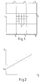
- Figure 1 illustrates by reference numeral 1 a subsidiary region of 4 X 4 image pixels 2. Each of these pixels has a value of L, I and Q associated with it.
- the TV signal ( Figure 4) from a device such as a TV receiver 19 is decoded to give red, green and blue signals.
- One frame of these RGB signals is continuously updated (Step 12, Figure 3) in a video memory 20.
- the operator views the stored image on a monitor 21. When he sees an image he wishes to capture, he indicates this in a conventional manner to the CPU 22 which in turn instructs the video memory 20 to start updating the image.
- the microcomputer first converts the RGB data to LIQ signals (Step 13) and divides each array into equal sized regions, each comprising a number of subsidiary regions having a size corresponding to 4 x 4 luminance pixels 2.
- One such region having nine subsidiary regions 1,3-10 is shown in Figure 1.
- a regression analysis is then carried out to calculate regression coefficients of the P and Q averages on L for the central subsidiary region 1 based on the average values determined for all the subsidiary regions 3-10.
- the regression analysis yields values for the two regression coefficients for the region 1 linking L and I.
- the microcomputer 22 determines (step 15) whether the linear function derived fits the L, I data well for the region. This may be achieved by obtaining the sum of the squares of the differences between each data point and the function and comparing with a predetermined threshold. If the sum is less than a threshold, the microcomputer then determines (step 16) a chromatic value (I) for each luminance pixel 1 using the regression coefficients just calculated. If the sum exceeds the threshold, the I values are left unchanged and step 17 is immediately processed.
- Steps 14, 15 are then repeated for the Q signal (step 17).
- each luminance pixel 2 (which may or may not be different from the original values) are then stored and the method repeated on the other major regions which will typically overlap so that each subsidiary region (eg. regions 3-10) of a major region will itself form a central subsidiary region of another major region.
- each subsidiary region eg. regions 3-10 of a major region will itself form a central subsidiary region of another major region.
- the LIQ information stored is transformed back to RGB (step 18) to enable the resultant image to be displayed on the monitor 21.
Landscapes
- Engineering & Computer Science (AREA)
- Multimedia (AREA)
- Signal Processing (AREA)
- Processing Of Color Television Signals (AREA)
Claims (6)
- Méthode de perfectionnement des transitions de signal de couleur en image vidéo définie par les données d'informatique de luminance et de chromaticité, la méthode comportant la génération de données modifiées de chromaticité par l'application d'un rapport prédéterminé entre les données de luminance et de chromaticité, caractérisée en ce que la méthode comporte en outre,a) la répartition de l'image en plusieurs régions, chacune comportant un nombre de régions secondaires;b) pour chaque région secondaire la définition d'un rapport statistique entre les données de luminance et les données de chromaticité; et,c) selon le niveau de corrélation entre les valeurs individuelles de chromaticité et de luminance avec le rapport statistique ainsi défini la génération de données modifiées de chromaticité pour un minimum d'une région secondaire de la région ainsi sélectionnée par l'application du rapport statistique ainsi défini aux données de luminance de ladite région secondaire.
- Méthode selon la revendication 1, dont la phase b) comporte l'analyse de régression pour générer un rapport entre la luminance (L) et une coordonnée de chrominance (I) selon la forme:

dont Fn est une série de fonction générale, telle qu'une série de puissance L. - Méthode selon la revendication 2, selon laquelle un rapport linéaire est défini entre luminance et chromaticité.
- Méthode selon l'une ou l'autre des revendications précédentes, selon laquelle la phase b) comporte la phase préliminaire d'application d'un procédé de calcul de la moyenne localisée à des régions secondaires (1,3-10) dans la région ainsi sélectionnée de manière à réduire les données de luminance à la même résolution spatiale que les données de chromaticité.
- Méthode selon l'une ou l'autre des revendications précédentes, de perfectionnement d'une image définie par un signal de luminance et deux signaux de chrominance, des rapports séparés étant déterminés en phase b) entre le signal de luminance et chaque signal de chrominance.
- Appareil de perfectionnement des transitions de signal de couleur en image vidéo définie par les données d'informatique de luminance et de chromaticité, l'appareil comportant des moyens de génération de données modifiées de chromaticité par l'application d'un rapport prédéterminé entre les données de luminance et de chromaticité; caractérisé en ce que l'appareil prévoit en outre des moyens de traitement (22)a) pour répartir l'image en plusieurs régions, chacune comportant un nombre de régions secondaires;b) pour définir un rapport statistique entre les données de luminance et les données de chromaticité de chaque région secondaire de l'image; et dont les moyens générateurs (22) de données modifiées de chromaticité assurent la génération de données modifiées de chromaticité pour un minimum d'une région secondaire de la région ainsi sélectionnée par l'application du rapport statistique ainsi défini aux données de luminance de ladite région secondaire selon le degré de corrélation entre les valeurs individuelles de chromaticité et de luminance avec le rapport statistique ainsi sélectionné.
Applications Claiming Priority (2)
| Application Number | Priority Date | Filing Date | Title |
|---|---|---|---|
| GB8700565 | 1987-01-12 | ||
| GB878700565A GB8700565D0 (en) | 1987-01-12 | 1987-01-12 | Video image enhancement |
Publications (2)
| Publication Number | Publication Date |
|---|---|
| EP0281709A1 EP0281709A1 (fr) | 1988-09-14 |
| EP0281709B1 true EP0281709B1 (fr) | 1993-05-26 |
Family
ID=10610551
Family Applications (1)
| Application Number | Title | Priority Date | Filing Date |
|---|---|---|---|
| EP87310445A Expired - Lifetime EP0281709B1 (fr) | 1987-01-12 | 1987-11-26 | Méthode pour l'amélioration d'une image vidéo couleur et appareil correspondant |
Country Status (5)
| Country | Link |
|---|---|
| US (1) | US4803548A (fr) |
| EP (1) | EP0281709B1 (fr) |
| JP (1) | JP2647666B2 (fr) |
| DE (1) | DE3786011T2 (fr) |
| GB (1) | GB8700565D0 (fr) |
Families Citing this family (15)
| Publication number | Priority date | Publication date | Assignee | Title |
|---|---|---|---|---|
| US5126726A (en) * | 1989-12-27 | 1992-06-30 | General Electric Company | Picture element encoding |
| FI86242C (fi) * | 1990-02-09 | 1992-07-27 | Salora Myynti Oy | Foerfarande foer behandling av en videosignal i komponentform. |
| US5608549A (en) * | 1991-06-11 | 1997-03-04 | Canon Kabushiki Kaisha | Apparatus and method for processing a color image |
| US5168375A (en) * | 1991-09-18 | 1992-12-01 | Polaroid Corporation | Image reconstruction by use of discrete cosine and related transforms |
| US5453787A (en) * | 1993-12-10 | 1995-09-26 | International Business Machines Corporation | Variable spatial frequency chrominance encoding in software motion video compression |
| US5465118A (en) * | 1993-12-17 | 1995-11-07 | International Business Machines Corporation | Luminance transition coding method for software motion video compression/decompression |
| US5509086A (en) * | 1993-12-23 | 1996-04-16 | International Business Machines Corporation | Automatic cross color elimination |
| GB2299477A (en) * | 1995-03-30 | 1996-10-02 | Sony Uk Ltd | Video filming scene correction |
| US6031581A (en) * | 1997-06-26 | 2000-02-29 | Xerox Corporation | System for removing color bleed in a television image adapted for digital printing |
| US6681042B1 (en) * | 2000-08-29 | 2004-01-20 | Eastman Kodak Company | Digital color image processing method |
| US6804392B1 (en) * | 2000-10-16 | 2004-10-12 | Eastman Kodak Company | Removing color aliasing artifacts from color digital images |
| US7072508B2 (en) * | 2001-01-10 | 2006-07-04 | Xerox Corporation | Document optimized reconstruction of color filter array images |
| EP1380177A1 (fr) * | 2001-04-11 | 2004-01-14 | Koninklijke Philips Electronics N.V. | Reglage du contraste de signaux image |
| US7079705B2 (en) * | 2002-10-30 | 2006-07-18 | Agilent Technologies, Inc. | Color interpolation for image sensors using a local linear regression method |
| US20060104537A1 (en) * | 2004-11-12 | 2006-05-18 | Sozotek, Inc. | System and method for image enhancement |
Family Cites Families (9)
| Publication number | Priority date | Publication date | Assignee | Title |
|---|---|---|---|---|
| US3778543A (en) * | 1972-09-05 | 1973-12-11 | Ellanin Investments | Predictive-retrospective method for bandwidth improvement |
| JPS5547792A (en) * | 1978-09-30 | 1980-04-04 | Hitachi Ltd | Chroma circuit |
| US4296433A (en) * | 1980-05-19 | 1981-10-20 | Matsushita Electric Corporation Of America | Color television receiving system with forced chroma transients |
| US4400721A (en) * | 1981-07-13 | 1983-08-23 | Albert Macovski | Transition system for color television receivers |
| JPS5871783A (ja) * | 1981-10-23 | 1983-04-28 | Sony Corp | 分離回路 |
| JPS59186493A (ja) * | 1983-04-07 | 1984-10-23 | Victor Co Of Japan Ltd | カラ−映像信号処理装置 |
| US4553157A (en) * | 1983-12-05 | 1985-11-12 | Rca Corporation | Apparatus for correcting errors in color signal transitions |
| US4630307A (en) * | 1984-09-10 | 1986-12-16 | Eastman Kodak Company | Signal processing method and apparatus for sampled image signals |
| DE3541103C1 (de) * | 1985-11-21 | 1986-12-18 | Philips Patentverwaltung Gmbh, 2000 Hamburg | Schaltungsanordnung zum Erhoehen der Schaerfe von Farbkanten |
-
1987
- 1987-01-12 GB GB878700565A patent/GB8700565D0/en active Pending
- 1987-11-26 DE DE8787310445T patent/DE3786011T2/de not_active Expired - Fee Related
- 1987-11-26 EP EP87310445A patent/EP0281709B1/fr not_active Expired - Lifetime
- 1987-12-01 US US07/127,144 patent/US4803548A/en not_active Expired - Fee Related
- 1987-12-28 JP JP62330336A patent/JP2647666B2/ja not_active Expired - Lifetime
Also Published As
| Publication number | Publication date |
|---|---|
| JP2647666B2 (ja) | 1997-08-27 |
| DE3786011D1 (de) | 1993-07-01 |
| GB8700565D0 (en) | 1987-02-18 |
| US4803548A (en) | 1989-02-07 |
| EP0281709A1 (fr) | 1988-09-14 |
| DE3786011T2 (de) | 1993-09-02 |
| JPS63182988A (ja) | 1988-07-28 |
Similar Documents
| Publication | Publication Date | Title |
|---|---|---|
| US4803548A (en) | Color video image enhancement | |
| CN100586159C (zh) | 处理视频信号的方法和系统 | |
| JP3293920B2 (ja) | 画像処理装置およびその方法 | |
| US5237402A (en) | Digital image processing circuitry | |
| KR100782818B1 (ko) | Yuv에서 rgb로 휘도 보존 컬러 변환 방법 및 시스템 | |
| US7280703B2 (en) | Method of spatially filtering a digital image using chrominance information | |
| US6614944B1 (en) | Image enhancement filter with adaptive threshold | |
| WO2019092463A1 (fr) | Traitement d'images vidéo | |
| CN111064942B (zh) | 图像处理方法和设备 | |
| DE69615878T2 (de) | Verarbeitung von halbtongerasterten Farbbildern | |
| US20020047933A1 (en) | Edge enhancement correction for improved image quality | |
| CN110298812A (zh) | 一种图像融合处理的方法及装置 | |
| US7263222B2 (en) | Automated color control in film-to-digital transfer | |
| EP1436980B1 (fr) | Reduction d'artefacts de diffusion chromatiques dans des images | |
| US4951129A (en) | Digital prefiltering of encoded video signals | |
| US7474337B1 (en) | Method and apparatus to provide edge enhancements as part of a demosaicing process | |
| US6163346A (en) | Dot crawl reduction in NTSC/PAL graphic encoder | |
| US5896465A (en) | Reverse prioritized image transmission | |
| EP0970578B1 (fr) | Minimisation des artefacts visuels provoques par l'affichage des pixels d'une image video | |
| EP1370091A1 (fr) | Traitement d'image | |
| US7724308B2 (en) | Cross color suppressing apparatus and method thereof | |
| MacDonald | Framework for an image sharpness management system | |
| KR100477657B1 (ko) | 디지털 화질 개선 방법 | |
| JP3244405B2 (ja) | 画像処理装置 | |
| JPS6354093A (ja) | カラー画像処理装置 |
Legal Events
| Date | Code | Title | Description |
|---|---|---|---|
| PUAI | Public reference made under article 153(3) epc to a published international application that has entered the european phase |
Free format text: ORIGINAL CODE: 0009012 |
|
| AK | Designated contracting states |
Kind code of ref document: A1 Designated state(s): DE GB |
|
| 17P | Request for examination filed |
Effective date: 19890302 |
|
| RAP1 | Party data changed (applicant data changed or rights of an application transferred) |
Owner name: CROSFIELD ELECTRONICS LIMITED |
|
| 17Q | First examination report despatched |
Effective date: 19920408 |
|
| RAP1 | Party data changed (applicant data changed or rights of an application transferred) |
Owner name: CROSFIELD ELECTRONICS LIMITED |
|
| GRAA | (expected) grant |
Free format text: ORIGINAL CODE: 0009210 |
|
| AK | Designated contracting states |
Kind code of ref document: B1 Designated state(s): DE GB |
|
| REF | Corresponds to: |
Ref document number: 3786011 Country of ref document: DE Date of ref document: 19930701 |
|
| PLBE | No opposition filed within time limit |
Free format text: ORIGINAL CODE: 0009261 |
|
| STAA | Information on the status of an ep patent application or granted ep patent |
Free format text: STATUS: NO OPPOSITION FILED WITHIN TIME LIMIT |
|
| 26N | No opposition filed | ||
| REG | Reference to a national code |
Ref country code: GB Ref legal event code: 732E |
|
| PGFP | Annual fee paid to national office [announced via postgrant information from national office to epo] |
Ref country code: GB Payment date: 19981127 Year of fee payment: 12 |
|
| PGFP | Annual fee paid to national office [announced via postgrant information from national office to epo] |
Ref country code: DE Payment date: 19981207 Year of fee payment: 12 |
|
| PG25 | Lapsed in a contracting state [announced via postgrant information from national office to epo] |
Ref country code: GB Free format text: LAPSE BECAUSE OF NON-PAYMENT OF DUE FEES Effective date: 19991126 |
|
| GBPC | Gb: european patent ceased through non-payment of renewal fee |
Effective date: 19991126 |
|
| PG25 | Lapsed in a contracting state [announced via postgrant information from national office to epo] |
Ref country code: DE Free format text: LAPSE BECAUSE OF NON-PAYMENT OF DUE FEES Effective date: 20000901 |