EP0281776A2 - Mehrschichtiges Rohr für das Formziehen und daraus hergestellter mehrschichtiger Behälter - Google Patents
Mehrschichtiges Rohr für das Formziehen und daraus hergestellter mehrschichtiger Behälter Download PDFInfo
- Publication number
- EP0281776A2 EP0281776A2 EP88101884A EP88101884A EP0281776A2 EP 0281776 A2 EP0281776 A2 EP 0281776A2 EP 88101884 A EP88101884 A EP 88101884A EP 88101884 A EP88101884 A EP 88101884A EP 0281776 A2 EP0281776 A2 EP 0281776A2
- Authority
- EP
- European Patent Office
- Prior art keywords
- layer
- evoh
- pes
- tube
- thickness
- Prior art date
- Legal status (The legal status is an assumption and is not a legal conclusion. Google has not performed a legal analysis and makes no representation as to the accuracy of the status listed.)
- Granted
Links
Images


Classifications
-
- B—PERFORMING OPERATIONS; TRANSPORTING
- B29—WORKING OF PLASTICS; WORKING OF SUBSTANCES IN A PLASTIC STATE IN GENERAL
- B29C—SHAPING OR JOINING OF PLASTICS; SHAPING OF MATERIAL IN A PLASTIC STATE, NOT OTHERWISE PROVIDED FOR; AFTER-TREATMENT OF THE SHAPED PRODUCTS, e.g. REPAIRING
- B29C48/00—Extrusion moulding, i.e. expressing the moulding material through a die or nozzle which imparts the desired form; Apparatus therefor
- B29C48/03—Extrusion moulding, i.e. expressing the moulding material through a die or nozzle which imparts the desired form; Apparatus therefor characterised by the shape of the extruded material at extrusion
- B29C48/09—Articles with cross-sections having partially or fully enclosed cavities, e.g. pipes or channels
- B29C48/10—Articles with cross-sections having partially or fully enclosed cavities, e.g. pipes or channels flexible, e.g. blown foils
-
- B—PERFORMING OPERATIONS; TRANSPORTING
- B29—WORKING OF PLASTICS; WORKING OF SUBSTANCES IN A PLASTIC STATE IN GENERAL
- B29C—SHAPING OR JOINING OF PLASTICS; SHAPING OF MATERIAL IN A PLASTIC STATE, NOT OTHERWISE PROVIDED FOR; AFTER-TREATMENT OF THE SHAPED PRODUCTS, e.g. REPAIRING
- B29C48/00—Extrusion moulding, i.e. expressing the moulding material through a die or nozzle which imparts the desired form; Apparatus therefor
- B29C48/03—Extrusion moulding, i.e. expressing the moulding material through a die or nozzle which imparts the desired form; Apparatus therefor characterised by the shape of the extruded material at extrusion
- B29C48/09—Articles with cross-sections having partially or fully enclosed cavities, e.g. pipes or channels
-
- B—PERFORMING OPERATIONS; TRANSPORTING
- B29—WORKING OF PLASTICS; WORKING OF SUBSTANCES IN A PLASTIC STATE IN GENERAL
- B29C—SHAPING OR JOINING OF PLASTICS; SHAPING OF MATERIAL IN A PLASTIC STATE, NOT OTHERWISE PROVIDED FOR; AFTER-TREATMENT OF THE SHAPED PRODUCTS, e.g. REPAIRING
- B29C48/00—Extrusion moulding, i.e. expressing the moulding material through a die or nozzle which imparts the desired form; Apparatus therefor
- B29C48/16—Articles comprising two or more components, e.g. co-extruded layers
- B29C48/18—Articles comprising two or more components, e.g. co-extruded layers the components being layers
- B29C48/21—Articles comprising two or more components, e.g. co-extruded layers the components being layers the layers being joined at their surfaces
-
- B—PERFORMING OPERATIONS; TRANSPORTING
- B29—WORKING OF PLASTICS; WORKING OF SUBSTANCES IN A PLASTIC STATE IN GENERAL
- B29C—SHAPING OR JOINING OF PLASTICS; SHAPING OF MATERIAL IN A PLASTIC STATE, NOT OTHERWISE PROVIDED FOR; AFTER-TREATMENT OF THE SHAPED PRODUCTS, e.g. REPAIRING
- B29C48/00—Extrusion moulding, i.e. expressing the moulding material through a die or nozzle which imparts the desired form; Apparatus therefor
- B29C48/25—Component parts, details or accessories; Auxiliary operations
- B29C48/30—Extrusion nozzles or dies
- B29C48/32—Extrusion nozzles or dies with annular openings, e.g. for forming tubular articles
- B29C48/335—Multiple annular extrusion nozzles in coaxial arrangement, e.g. for making multi-layered tubular articles
- B29C48/336—Multiple annular extrusion nozzles in coaxial arrangement, e.g. for making multi-layered tubular articles the components merging one by one down streams in the die
- B29C48/3366—Multiple annular extrusion nozzles in coaxial arrangement, e.g. for making multi-layered tubular articles the components merging one by one down streams in the die using a die with concentric parts, e.g. rings, cylinders
-
- B—PERFORMING OPERATIONS; TRANSPORTING
- B29—WORKING OF PLASTICS; WORKING OF SUBSTANCES IN A PLASTIC STATE IN GENERAL
- B29C—SHAPING OR JOINING OF PLASTICS; SHAPING OF MATERIAL IN A PLASTIC STATE, NOT OTHERWISE PROVIDED FOR; AFTER-TREATMENT OF THE SHAPED PRODUCTS, e.g. REPAIRING
- B29C49/00—Blow-moulding, i.e. blowing a preform or parison to a desired shape within a mould; Apparatus therefor
- B29C49/22—Blow-moulding, i.e. blowing a preform or parison to a desired shape within a mould; Apparatus therefor using multilayered preforms or parisons
-
- B—PERFORMING OPERATIONS; TRANSPORTING
- B32—LAYERED PRODUCTS
- B32B—LAYERED PRODUCTS, i.e. PRODUCTS BUILT-UP OF STRATA OF FLAT OR NON-FLAT, e.g. CELLULAR OR HONEYCOMB, FORM
- B32B1/00—Layered products having a non-planar shape
-
- B—PERFORMING OPERATIONS; TRANSPORTING
- B32—LAYERED PRODUCTS
- B32B—LAYERED PRODUCTS, i.e. PRODUCTS BUILT-UP OF STRATA OF FLAT OR NON-FLAT, e.g. CELLULAR OR HONEYCOMB, FORM
- B32B1/00—Layered products having a non-planar shape
- B32B1/08—Tubular products
-
- B—PERFORMING OPERATIONS; TRANSPORTING
- B32—LAYERED PRODUCTS
- B32B—LAYERED PRODUCTS, i.e. PRODUCTS BUILT-UP OF STRATA OF FLAT OR NON-FLAT, e.g. CELLULAR OR HONEYCOMB, FORM
- B32B27/00—Layered products comprising a layer of synthetic resin
- B32B27/06—Layered products comprising a layer of synthetic resin as the main or only constituent of a layer, which is next to another layer of the same or of a different material
- B32B27/08—Layered products comprising a layer of synthetic resin as the main or only constituent of a layer, which is next to another layer of the same or of a different material of synthetic resin
-
- B—PERFORMING OPERATIONS; TRANSPORTING
- B32—LAYERED PRODUCTS
- B32B—LAYERED PRODUCTS, i.e. PRODUCTS BUILT-UP OF STRATA OF FLAT OR NON-FLAT, e.g. CELLULAR OR HONEYCOMB, FORM
- B32B27/00—Layered products comprising a layer of synthetic resin
- B32B27/30—Layered products comprising a layer of synthetic resin comprising vinyl (co)polymers; comprising acrylic (co)polymers
- B32B27/306—Layered products comprising a layer of synthetic resin comprising vinyl (co)polymers; comprising acrylic (co)polymers comprising vinyl acetate or vinyl alcohol (co)polymers
-
- B—PERFORMING OPERATIONS; TRANSPORTING
- B32—LAYERED PRODUCTS
- B32B—LAYERED PRODUCTS, i.e. PRODUCTS BUILT-UP OF STRATA OF FLAT OR NON-FLAT, e.g. CELLULAR OR HONEYCOMB, FORM
- B32B27/00—Layered products comprising a layer of synthetic resin
- B32B27/36—Layered products comprising a layer of synthetic resin comprising polyesters
-
- B—PERFORMING OPERATIONS; TRANSPORTING
- B32—LAYERED PRODUCTS
- B32B—LAYERED PRODUCTS, i.e. PRODUCTS BUILT-UP OF STRATA OF FLAT OR NON-FLAT, e.g. CELLULAR OR HONEYCOMB, FORM
- B32B7/00—Layered products characterised by the relation between layers; Layered products characterised by the relative orientation of features between layers, or by the relative values of a measurable parameter between layers, i.e. products comprising layers having different physical, chemical or physicochemical properties; Layered products characterised by the interconnection of layers
- B32B7/04—Interconnection of layers
- B32B7/12—Interconnection of layers using interposed adhesives or interposed materials with bonding properties
-
- B—PERFORMING OPERATIONS; TRANSPORTING
- B29—WORKING OF PLASTICS; WORKING OF SUBSTANCES IN A PLASTIC STATE IN GENERAL
- B29C—SHAPING OR JOINING OF PLASTICS; SHAPING OF MATERIAL IN A PLASTIC STATE, NOT OTHERWISE PROVIDED FOR; AFTER-TREATMENT OF THE SHAPED PRODUCTS, e.g. REPAIRING
- B29C2949/00—Indexing scheme relating to blow-moulding
- B29C2949/07—Preforms or parisons characterised by their configuration
- B29C2949/081—Specified dimensions, e.g. values or ranges
- B29C2949/0811—Wall thickness
- B29C2949/0819—Wall thickness of a layer
-
- B—PERFORMING OPERATIONS; TRANSPORTING
- B29—WORKING OF PLASTICS; WORKING OF SUBSTANCES IN A PLASTIC STATE IN GENERAL
- B29C—SHAPING OR JOINING OF PLASTICS; SHAPING OF MATERIAL IN A PLASTIC STATE, NOT OTHERWISE PROVIDED FOR; AFTER-TREATMENT OF THE SHAPED PRODUCTS, e.g. REPAIRING
- B29C2949/00—Indexing scheme relating to blow-moulding
- B29C2949/07—Preforms or parisons characterised by their configuration
- B29C2949/081—Specified dimensions, e.g. values or ranges
- B29C2949/082—Diameter
-
- B—PERFORMING OPERATIONS; TRANSPORTING
- B29—WORKING OF PLASTICS; WORKING OF SUBSTANCES IN A PLASTIC STATE IN GENERAL
- B29C—SHAPING OR JOINING OF PLASTICS; SHAPING OF MATERIAL IN A PLASTIC STATE, NOT OTHERWISE PROVIDED FOR; AFTER-TREATMENT OF THE SHAPED PRODUCTS, e.g. REPAIRING
- B29C2949/00—Indexing scheme relating to blow-moulding
- B29C2949/07—Preforms or parisons characterised by their configuration
- B29C2949/081—Specified dimensions, e.g. values or ranges
- B29C2949/0829—Height, length
-
- B—PERFORMING OPERATIONS; TRANSPORTING
- B29—WORKING OF PLASTICS; WORKING OF SUBSTANCES IN A PLASTIC STATE IN GENERAL
- B29K—INDEXING SCHEME ASSOCIATED WITH SUBCLASSES B29B, B29C OR B29D, RELATING TO MOULDING MATERIALS OR TO MATERIALS FOR MOULDS, REINFORCEMENTS, FILLERS OR PREFORMED PARTS, e.g. INSERTS
- B29K2023/00—Use of polyalkenes or derivatives thereof as moulding material
- B29K2023/04—Polymers of ethylene
- B29K2023/06—PE, i.e. polyethylene
-
- B—PERFORMING OPERATIONS; TRANSPORTING
- B29—WORKING OF PLASTICS; WORKING OF SUBSTANCES IN A PLASTIC STATE IN GENERAL
- B29K—INDEXING SCHEME ASSOCIATED WITH SUBCLASSES B29B, B29C OR B29D, RELATING TO MOULDING MATERIALS OR TO MATERIALS FOR MOULDS, REINFORCEMENTS, FILLERS OR PREFORMED PARTS, e.g. INSERTS
- B29K2023/00—Use of polyalkenes or derivatives thereof as moulding material
- B29K2023/04—Polymers of ethylene
- B29K2023/08—Copolymers of ethylene
- B29K2023/083—EVA, i.e. ethylene vinyl acetate copolymer
-
- B—PERFORMING OPERATIONS; TRANSPORTING
- B29—WORKING OF PLASTICS; WORKING OF SUBSTANCES IN A PLASTIC STATE IN GENERAL
- B29K—INDEXING SCHEME ASSOCIATED WITH SUBCLASSES B29B, B29C OR B29D, RELATING TO MOULDING MATERIALS OR TO MATERIALS FOR MOULDS, REINFORCEMENTS, FILLERS OR PREFORMED PARTS, e.g. INSERTS
- B29K2023/00—Use of polyalkenes or derivatives thereof as moulding material
- B29K2023/04—Polymers of ethylene
- B29K2023/08—Copolymers of ethylene
- B29K2023/086—EVOH, i.e. ethylene vinyl alcohol copolymer
-
- B—PERFORMING OPERATIONS; TRANSPORTING
- B29—WORKING OF PLASTICS; WORKING OF SUBSTANCES IN A PLASTIC STATE IN GENERAL
- B29K—INDEXING SCHEME ASSOCIATED WITH SUBCLASSES B29B, B29C OR B29D, RELATING TO MOULDING MATERIALS OR TO MATERIALS FOR MOULDS, REINFORCEMENTS, FILLERS OR PREFORMED PARTS, e.g. INSERTS
- B29K2067/00—Use of polyesters or derivatives thereof, as moulding material
-
- B—PERFORMING OPERATIONS; TRANSPORTING
- B29—WORKING OF PLASTICS; WORKING OF SUBSTANCES IN A PLASTIC STATE IN GENERAL
- B29K—INDEXING SCHEME ASSOCIATED WITH SUBCLASSES B29B, B29C OR B29D, RELATING TO MOULDING MATERIALS OR TO MATERIALS FOR MOULDS, REINFORCEMENTS, FILLERS OR PREFORMED PARTS, e.g. INSERTS
- B29K2623/00—Use of polyalkenes or derivatives thereof for preformed parts, e.g. for inserts
- B29K2623/04—Polymers of ethylene
- B29K2623/08—Copolymers of ethylene
- B29K2623/086—EVOH, i.e. ethylene vinyl alcohol copolymer
-
- B—PERFORMING OPERATIONS; TRANSPORTING
- B32—LAYERED PRODUCTS
- B32B—LAYERED PRODUCTS, i.e. PRODUCTS BUILT-UP OF STRATA OF FLAT OR NON-FLAT, e.g. CELLULAR OR HONEYCOMB, FORM
- B32B2331/00—Polyvinylesters
- B32B2331/04—Polymers of vinyl acetate, e.g. PVA
-
- B—PERFORMING OPERATIONS; TRANSPORTING
- B32—LAYERED PRODUCTS
- B32B—LAYERED PRODUCTS, i.e. PRODUCTS BUILT-UP OF STRATA OF FLAT OR NON-FLAT, e.g. CELLULAR OR HONEYCOMB, FORM
- B32B2367/00—Polyesters, e.g. PET, i.e. polyethylene terephthalate
-
- B—PERFORMING OPERATIONS; TRANSPORTING
- B32—LAYERED PRODUCTS
- B32B—LAYERED PRODUCTS, i.e. PRODUCTS BUILT-UP OF STRATA OF FLAT OR NON-FLAT, e.g. CELLULAR OR HONEYCOMB, FORM
- B32B2439/00—Containers; Receptacles
-
- B—PERFORMING OPERATIONS; TRANSPORTING
- B32—LAYERED PRODUCTS
- B32B—LAYERED PRODUCTS, i.e. PRODUCTS BUILT-UP OF STRATA OF FLAT OR NON-FLAT, e.g. CELLULAR OR HONEYCOMB, FORM
- B32B2597/00—Tubular articles, e.g. hoses, pipes
-
- Y—GENERAL TAGGING OF NEW TECHNOLOGICAL DEVELOPMENTS; GENERAL TAGGING OF CROSS-SECTIONAL TECHNOLOGIES SPANNING OVER SEVERAL SECTIONS OF THE IPC; TECHNICAL SUBJECTS COVERED BY FORMER USPC CROSS-REFERENCE ART COLLECTIONS [XRACs] AND DIGESTS
- Y10—TECHNICAL SUBJECTS COVERED BY FORMER USPC
- Y10T—TECHNICAL SUBJECTS COVERED BY FORMER US CLASSIFICATION
- Y10T428/00—Stock material or miscellaneous articles
- Y10T428/13—Hollow or container type article [e.g., tube, vase, etc.]
- Y10T428/1352—Polymer or resin containing [i.e., natural or synthetic]
- Y10T428/1379—Contains vapor or gas barrier, polymer derived from vinyl chloride or vinylidene chloride, or polymer containing a vinyl alcohol unit
- Y10T428/1383—Vapor or gas barrier, polymer derived from vinyl chloride or vinylidene chloride, or polymer containing a vinyl alcohol unit is sandwiched between layers [continuous layer]
-
- Y—GENERAL TAGGING OF NEW TECHNOLOGICAL DEVELOPMENTS; GENERAL TAGGING OF CROSS-SECTIONAL TECHNOLOGIES SPANNING OVER SEVERAL SECTIONS OF THE IPC; TECHNICAL SUBJECTS COVERED BY FORMER USPC CROSS-REFERENCE ART COLLECTIONS [XRACs] AND DIGESTS
- Y10—TECHNICAL SUBJECTS COVERED BY FORMER USPC
- Y10T—TECHNICAL SUBJECTS COVERED BY FORMER US CLASSIFICATION
- Y10T428/00—Stock material or miscellaneous articles
- Y10T428/13—Hollow or container type article [e.g., tube, vase, etc.]
- Y10T428/1352—Polymer or resin containing [i.e., natural or synthetic]
- Y10T428/139—Open-ended, self-supporting conduit, cylinder, or tube-type article
- Y10T428/1393—Multilayer [continuous layer]
-
- Y—GENERAL TAGGING OF NEW TECHNOLOGICAL DEVELOPMENTS; GENERAL TAGGING OF CROSS-SECTIONAL TECHNOLOGIES SPANNING OVER SEVERAL SECTIONS OF THE IPC; TECHNICAL SUBJECTS COVERED BY FORMER USPC CROSS-REFERENCE ART COLLECTIONS [XRACs] AND DIGESTS
- Y10—TECHNICAL SUBJECTS COVERED BY FORMER USPC
- Y10T—TECHNICAL SUBJECTS COVERED BY FORMER US CLASSIFICATION
- Y10T428/00—Stock material or miscellaneous articles
- Y10T428/24—Structurally defined web or sheet [e.g., overall dimension, etc.]
- Y10T428/24942—Structurally defined web or sheet [e.g., overall dimension, etc.] including components having same physical characteristic in differing degree
- Y10T428/2495—Thickness [relative or absolute]
-
- Y—GENERAL TAGGING OF NEW TECHNOLOGICAL DEVELOPMENTS; GENERAL TAGGING OF CROSS-SECTIONAL TECHNOLOGIES SPANNING OVER SEVERAL SECTIONS OF THE IPC; TECHNICAL SUBJECTS COVERED BY FORMER USPC CROSS-REFERENCE ART COLLECTIONS [XRACs] AND DIGESTS
- Y10—TECHNICAL SUBJECTS COVERED BY FORMER USPC
- Y10T—TECHNICAL SUBJECTS COVERED BY FORMER US CLASSIFICATION
- Y10T428/00—Stock material or miscellaneous articles
- Y10T428/31504—Composite [nonstructural laminate]
- Y10T428/31786—Of polyester [e.g., alkyd, etc.]
- Y10T428/31797—Next to addition polymer from unsaturated monomers
-
- Y—GENERAL TAGGING OF NEW TECHNOLOGICAL DEVELOPMENTS; GENERAL TAGGING OF CROSS-SECTIONAL TECHNOLOGIES SPANNING OVER SEVERAL SECTIONS OF THE IPC; TECHNICAL SUBJECTS COVERED BY FORMER USPC CROSS-REFERENCE ART COLLECTIONS [XRACs] AND DIGESTS
- Y10—TECHNICAL SUBJECTS COVERED BY FORMER USPC
- Y10T—TECHNICAL SUBJECTS COVERED BY FORMER US CLASSIFICATION
- Y10T428/00—Stock material or miscellaneous articles
- Y10T428/31504—Composite [nonstructural laminate]
- Y10T428/31855—Of addition polymer from unsaturated monomers
- Y10T428/31935—Ester, halide or nitrile of addition polymer
Definitions
- the present invention relates to a multilayered tube comprising a saturated polyester ( hereinafter referred to as PES ) as the inner and the outer layers, a saponified product of ethylene-vinyl acetate copolymer ( hereinafter referred to as EVOH ) as the intermediate layer, and an adhesive resin (hereinafter referred to as TR ) layer between the PES layers and the EVOH layer; and a multilayered container made from the tube; as well as methods of producing the tube and the container.
- PES saturated polyester
- EVOH saponified product of ethylene-vinyl acetate copolymer
- TR adhesive resin
- PES represented by polyethylene terephthalate ( hereinafter referred to as PET ) is, because of its high transparency, heat resistance, mechanical properties, and so on, widely used not only for fibers and films but also for containers for beverages and foods or as films for food packaging.
- PET polyethylene terephthalate
- PES polyethylene terephthalate
- it is to some extent suitable for preserving foods as it possesses certain gas barrier properties.
- superior gas barrier properties are desired depending on the type of foods or beverages to be filled or packed therein. Attempts have therefore been made to laminate the EVOH, resin, which has a higher gas barrier property onto PES to obtain tubes, blown bottles and films having multilayered structures.
- JP-A-108162/1978, 77144/1981, 128516/1982, US-A-4 504 531 and JP-A-199237/1984 disclose tubes and blown bottles made from laminates of the two resins.
- the container shows abnormal nonuniformity giving the impression of streaks which render the bottle unsatisfactory.
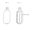
- Figure 10 is an elevation of such a bottle, showing streaky nonuniformities. This streakiness, S (hereinafter referred to simply as streaks), markedly lowers the commercial value of the bottle, and the bottle cannot stand comparison with monolayered bottles of PET which are sold commercially.
- the present inventors thought that such streaks of the blown bottles cannot be fully eliminated by improving the uniformity in the thickness of the tube or the EVOH layer or each layer, and that the streaks are caused by the poor drawability of the EVOH used as the gas barrier resin. They have carried out a series of studies centering on improving the blow molding conditions such as blow ratio, blow rate and blow temperature and various manufacturing conditions. However, they found that drawability can only be improved to a certain degree, by improving the blow conditions or various manufacturing conditions. The desired bottles free from streaks were difficult to obtain.
- the present inventors made further intensive studies on the streaks problem and found unexpectedly that the main factor causing the streaks are local minute nonuniformities in the thickness of small regions of the EVOH layer in the tube. More specifically, local minute nonuniformities in the thickness (roughness) of the EVOH layer in the tube cause bigger irregularities in the EVOH layer and bottle wall thickness in the course of biaxial draw blowing.
- the local minute nonuniformities in thickness are continuously generated in flow direction at the junction in the die, when the tube is molded and appears as continuous "streaks" along the machine direction in the article. It is indispensable to eliminate such local minute unevenness.
- the present invention has been achieved based on the above findings, and provides a multilayered tube for draw molding, which comprises a saturated polyester as the inner and outer layers, a saponified product of an ethylene-vinyl acetate copolymer having a ethylene content of 20 to 55 mol% and a saponification degree of the vinyl acetate component of at least 96 mol%, and an adhesive resin layer interposed between the saturated polyester layer and the saponified product of the ethylene-vinyl acetate copolymer layer; which satisfies the conditions of the following formulae I- 1 to I-3: wherein,
- Emax is the maximum wall thickness ( ⁇ m) in the above specified region between P n and P n+1 .
- Figure 1 shows the thickness distribution in the circumferential direction of the EVOH layer in the cross section of a bottle ⁇ point A is the maximum thickness (tmax); point B is the minimum thickness (tmin); the distance between tmax and tmin is (L) ⁇ .
- the abscissa represents the circumferential distance and the ordinate represents the thickness of the EVOH layer.
- Figure 2 is a diagram showing local minute nonuniformities in the thickness of the EVOH layer ⁇ Emax and Emin are the maximum thickness and the minimum thickness respectively between points P n and P n+ i the circumferential distance between them being Q ( ⁇ m).
- Figure 3 shows a curve delimiting the acceptable region ( hatched ) for the local minute nonuniformity in the thickness of the tube according to the present invention, which is expressed by the following equation: wherein the abscissa represents Q and the ordinate represents K.
- Figure 4 is a perspective view of the EVOH layer of the tube.
- Figure 5 shows the manufacturing process for the tube according to the present invention.
- Figure 6-(1) is a sectional view of a co-extrusion die used in manufacturing the tube according to the present invention
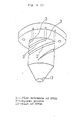
- Figure 6-(2) is a perspective view of a mandrel having a spiral structure.
- Figures 7-(1) to (4) are diagrams of other co-extrusion dies used in manufacturing the tube of the present invention.
- Figure 8 shows a sectional view of the tube of Example 1.
- Figure 9 is an elevation of the biaxially drawn blown bottle having no streaks obtained from the tube of Example 1.
- Figure 10 is an elevation of the biaxially drawn blown bottle having streaks obtained from the tube of Comparative Example 1.
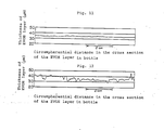
- Figure 11 shows the thickness distribution of the EVOH layer of the bottle prepared in Example 1.
- Figure 12 shows the thickness distribution of the EVOH layer of the bottle prepared in Comparative Example 1.
- the abscissa represents the circumferential distance in the cross section of the bottle and the ordinate represents the thickness of the EVOH layer.
- Figure 13-(1) is a diagram of a coextrusion die used in manufacturing the tube according to the present invention when TR is introduced; and (2) when both TR and EVOH are introduced.
- the EVOH layer as the intermediate layer of a multilayered tube should satisfy the above equation II. This means that any local nonuniformity in thickness must be eliminated from the minute regions.
- the present inventors have carried out a number of basic experiments and molding tests. As a result, they found that for the purpose of obtaining a biaxially drawn blown bottle of PES/TR/EVOH/TR/PES, that is a bottle with five layers of three different materials, which is substantially free from streaks, it is not sufficient to simply improve the structure of the multilayered tube by controlling the thickness of the EVOH layer and eliminating thickness irregularities in the TR layer. Rather it is necessary to eliminate local minute variations in the thickness of the EVOH layer in the tube, that is, the condition (II) must be fulfilled.
- the problem of streaks caused by the poor drawability of EVOH is usually not encountered in other multilayered structures comprising PES, polyethylene, polypropyrene, nylon, etc., but no EVOH.
- the above condition II is substantially satisfied, if all or almost all points in the EVOH layer in the cross section of the tube satisfy the condition II.
- minute local thickness irregularities (not satisfying the condition II) not causing the appearance of streaks upon drawing may be allowed to exist.
- two points of two cross sections of the tube which are 1 to 2 cm apart from each other in the longitudinal direction of the tube, do not simultaneously satisfy the condition II, since the points will form a streak upon drawing. If only one of these points of the EVOH layer does not satisfy the condition II, a streak may be avoided.
- Emax and Emin are determined by cutting the tube at two points which are 1 to 2 cm apart from each other in the longitudinal direction and by measuring the maximum and minimum thickness within a range Q of 100 to 500 um in the two cross sections.
- Tubes satisfying the condition II in both of the cross sections, as well as tubes in which one of the two sections contains a point not satisfying the condition II while the other section satisfies the condition II are included in the present invention.
- tubes, where in one cross section there is a point which does not satisfy the condition II and in the other cross section there is a point linked lineally with the first point which does not satisfy the condition II either, are excluded from the present invention, as they will form streaks upon drawing.
- the maximum allowable range for the thickness irregularity of the EVOH layer calculated from the inequality I- 2 1 - 0.01 H ⁇ E/ E ⁇ 1 + 0.01 H ., is 210-390 um.
- Figure 2 is a diagrammatical view of the cross section of the tube according to the present invention showing local minute nonuniformity in the thickness of the EVOH layer.
- Figure 3 shows the acceptable region ( hatched ) for the local minute nonuniformity in thickness of the tube according to the present invention, wherein the abscissa represents Q(um) and the ordinate represents:
- the graph of Figure 3 shows that the variation in the acceptable range of thickness nonuniformity forms a gradient which is a function of the length Q of the local minute segment.
- the acceptable value of the thickness nonuniformity (gradient K) becomes smaller as the minute region Q becomes longer. This means that even a gentle slope will increase the drawing nonuniformity which cases streaks.
- the gradient element is the thickness variation is an important factor, an irregularity which, while satisfying the condition II in a minute region of substantially Q ⁇ 100 um, would cause streak formation, is never produced in the actual molding practice as judged from interfacial characteristics of the polymer flow. Therefore it is sufficient to fix the lower limit of Q to be 100 ⁇ m.
- Q 500 u.m. For instance even when Q is as great as 2000 um, the gradient does not show a big variation.
- the total range of thickness and local minute thickness nonuniformities of an EVOH layer is measured following the procedures below.
- the TR layer and the EVOH are relatively transparent the boundary lines can be seen from differences in refractivity and color shade to make possible measurement of relatively larger irregularities.
- Also effective is a method, experimentally, of coloring each polymer beforehand to distinguish them clearly from each other for an easier observation. It happens that a sample rejected by observation of the cross section may be an accidental defective due to contamination with foreign substances, etc., which will not cause a streak. In this case it is necessary to do rechecking by further observing residual samples to see if it is really a continuous minute nonuniformity in thickness.
- the present inventors have also studied how to take out the EVOH layer without damaging it from a multilayered tube, and have found an effective method to measure the thickness, thus making it possible to have the EVOH layer only be observed with the naked eye or with a special microscope as well as subjected to measurement with a thickness tester. That is, in the case where the softening point of the TR layer is lower than those of PES and EVOH, the following method is effective as well as simple and easy.
- Figure 4 shows a perspective view of the EVOH layer obtained from the tube. Most simply, the thus obtained EVOH layer is held into the light and examined for local minute nonuniformities C (cavity) and D (projection) of a few u.m in thickness which appear as thin streaks; by such sensory evaluation or comparison with the naked eye it is in most cases possible to judge whether the specimen is acceptable or not.
- C cavity
- D projection
- Another effective method is checking and rough measurement of the thickness nonuniformities by examining with a microscope a cross section in the circumferential direction (direction perpendicular to the tube axis) of the tube.
- the multilayered tube must satisfy the aforedescribed inequalities I- 1 to I- 3 .
- I- 1 specifies the thickness range of the EVOH layer. It is true that when the EVOH layer is made thinner, the layer is drawn more uniformly forming less streaks. However, an improvement in the barrier property which should be the main reason for using a multilayered material cannot be achieved, if the EVOH layer is made too thin. Furthermore, if the EVOH layer is less than 50 um, it is very difficult to maintain a continuous molding of a multilayered tube having a uniform EVOH layer of small thickness biases for a long time. Consequently, the thickness should be 50 u.m or more, preferably 150 u.m or more. On the other hand, as the EVOH layer is made thicker, the poor drawability of EVOH becomes a problem and irregularities upon drawing will increase.
- the thickness be not more than 1000 ⁇ m and more preferably: 150 ⁇ m ⁇ E 5 700u.m. From the viewpoint of the gas barrier property required for bottles for commercially available refreshing drinks a thickness of 700 ⁇ m (about 50 um after drawing) or below will be sufficient.
- I-2 govern the allowable variation in the thickness of the EVOH layer.
- Prevention of biased thickness of the EVOH layer is very difficult because of the poor flow characteristics of the EVOH.
- a biased thickness directly causes nonuniformity of drawing and generation of streaks, a variety of studies have been made on how to fix acceptable limits of biased thickness. As a result therefrom, it was found that the acceptable limits of biased thickness can, in relationship with the tube diameter (H), be well specified to be:
- I- 3 refers to the ratio of the EVOH layer to the PES layers. While it is not deemed to be so important a factor in a general multilayered tube, this ratio is an important condition for obtaining a streakless bottle by uniformly drawing a multilayered tube containing an EVOH layer.
- PES layers have an important function in the uniform drawing of EVOH which is by itself of poor drawability, which is helped by their co-drawing. Where the ratio of the PES layers is small, the PES layers themselves will be affected by the poor drawability of the EVOH layer, and the bottle will show greater irregularities in thickness because of nonuniform drawing which will make it difficult to avoid streaks. For this reason it is preferred that E / ( A + B ) be 0.2 or less , more preferably 0.15 or less.
- the multilayered tube according to the present invention should satisfy the following conditions IV -1 to IV - 13: wherein:
- IV - 1 to IV - 13 are preferred conditions for the multilayered tube used for draw molding according to the present invention.
- IV -1 specifies the size of the multilayered structure of this invention, which is preferably in the range from 15 to 50 mm for the following reasons: With a multilayered tube having an outer diameter of 15 mm or smaller, a high-thickness molding is difficult to carry out. There are restrictions on the caliber and body diameter of the bottle resulting from limitations in the drawing ratio of the body. Also, if the ratio (surface area of bottle)/(volume of bottle) is too high it will adversely affect the barrier effect. Therefore, a diameter of 15 mm or higher is preferred.
- a multilayered tube having an outer diameter of 50 mm or greater involves several drawbacks including an inevitable enlargement of the body diameter due to a minimum required drawing ratio. This requires higher pressure resistance and necessitates a thicker wall, and gives rise to restrictions on the bottle caliber by the tube diameter. Consequently, the preparation of preforms is difficult.
- IV - 2 specifies the deformation ratio of the tube expressed as the tolerance of the outer diameter of the tube. When the tolerance is too large, the following troubles will occur:
- the tolerance of the outer diameter be ⁇ 2 % or below, preferably ⁇ 1 % or below.
- IV -3 specifies the range of the wall thickness of the tube.
- a thin wall of 1000um or thinner is difficult to prepare by multilayer molding on account of irregular thickness, deformation of the tube, and the like.
- the wall thickness becomes thin and so liable to deform from or damage by an external force as to make the bottle unsuitable for use.
- a thick wall of 7000um or thicker will make worse the heat transfer, and cause whitening phenomena to occur at portions of EVOH layer or PES layer due to crystallization, thus rendering it difficult to obtain a bottle having a transparent appearance.
- a more preferred range is 1500 ⁇ m ⁇ Z 5 6000um.
- IV -4 specifies the tolerance of the thickness of the entire tube wall.
- the nonuniformities in drawing and heating during the drawing will increase the bias so as to show up large biased wall portions. These portions will cause the deformation of the tube, the deformation of the bottle, resulting in poor strength, poor barrier property, etc. Consequently, the bottle will not be satisfactory.
- the nonuniformity in drawing will add to increase streaks, and the biased thickness of the whole wall affects the quality of preform making.
- the whole wall thickness bias should be t 15 % or below, preferably ⁇ 10 % or below
- IV - 5 specifies the range of wall thickness of the inner PES layer.
- the wall thickness of the inner layer is 300 ⁇ m or below, not only molding of the tube becomes difficult.
- the EVOH layer is placed closer to the inside of the bottle, when used as a bottle for water-containing beverages such as beverages containing carbon dioxide gas, the water content of the EVOH becomes higher, whereby the barrier property markedly decreases and is rendered insufficient.
- the EVOH layer slides towards the inside because of a thinner inner layer the external cooling effect at the time the tube is subjected to sizing cooling will be lower resulting in a whitening due to crystallization.
- disorders of the inner layer occur if the inner layer is too thin and the preparation of a good preform becomes thus difficult.
- the wall thickness of the inner PES layer is preferably 300 ⁇ m or above, more preferably 500u.m or above.
- too thick a wall of 5000u.m or thicker will involve problems such as increased dissolution of the inner PES layer by the carbon dioxide gas contained in a carbon dioxide gas beverage, lower resistance to the internal gas pressure which in turn causes delamination at the adhesive resin layer, and so on. Therefore, the wall thickness of the inner PES layer is not more than 5000u.m, more preferably not more than 4000 ⁇ m.
- IV - 6 specifies the tolerances for the thickness of the inner PES layer. Since too high a variation causes nonuniformity in the gas barrier property, and since a good balance is required for good preforming and good blow molding, as in cases of inequalities IV -2 and IV -4, the tolerance is ⁇ 25 %, preferably ⁇ 20%.
- IV - 7 specifies the range of the thickness of the outer PES layer.
- a layer of 150 ⁇ m or less is difficult to mold.
- too thin an outer PES layer will, as in the case of a pressure bottle such as the one for carbonate beverages, pose the problem of delamination in the intermediate EVOH layer caused by the stress generated in the adhesive resin layer.
- a construction comprising a PES layer more than 4000u.m thick will, though the molding is possible, shift the EVOH layer inwardly, that is, to the high-moisture side ,resulting in reduced barrier properties and external cooling effect of the EVOH layer.
- IV -8 specifies tolerances for the wall thickness of the outer PES layer to be ⁇ 25 %, more preferably ⁇ 20 %, to ensure a good balance for achieving good preforming and good bottle molding, as in IV - 6.
- IV - 9 specifies the ratio of the wall thickness of the inner PES layer and the outer PES layer.
- the ratio stands for a construction showing the position of the EVOH in the tube wall, and is, as explained in IV -5 and IV -7, a very important factor in tube and bottle molding and, particularly for bottle performance.
- the tube and B / A is made smaller; when the tube is later processed into a gas barrier container for water-containing beverages such as carbonated drinks, decrease in the barrier property will be avoided to some extent.
- the inner gas pressure to which the EVOH layer is exposed also acts upon the thin outer PES layer, the stress in the TR layer between the inner and outer layers of PES becomes so great as to produce a delamination between the EVOH layer and TR layer.
- the EVOH layer gets closer to the liquid contained, i.e. to high-moisture area, whereby it suffers a loss in its barrier property.
- the container is to hold and the required performances, such as pressure resistance, gas barrier property, etc.
- the barrier property decreases in the presence of moisture
- the delamination problem can be solved by selecting the bond strength of TR. Therefore it is recommended that the EVOH layer be shifted a little to the outside of its intermediate layer position.
- the wall thickness ratio B/A of the inner and outer PES layers is too high or too low, a bias or nonuniformity in thickness of the thin PES layer forms.
- the construction ratio is preferably 0.1 ⁇ B / A ⁇ 5, more preferably 0.25 ⁇ B / A ⁇ 2.5.
- TR is a layer bonding the PES layers with the EVOH layer and is of particular importance in preparing a biaxially drawn container from a multilayered tube.
- the TR layer must satisfy the following conditions:
- the condition (iv), that is of TR being capable of allowing the EVOH layer to be uniformly drawn is the most important one. Therefore, an adhesive resin layer is not simply a layer to be interposed between the PES layer and the EVOH layer, but must satisfy the above conditions.
- the thickness of the inner and outer layers, C and D are each 10 ⁇ m to 300 um, preferably 30 u.m to 100 ⁇ m.
- the TR layer tends to delaminate from the EVOH layer owing to a difference in the shrinkage stress on cooling in the tube molding process or to external stress on tube cutting, or to a deformation stress due to internal gas pressure of the bottle.
- the thickness exceeds 300 um, the bond between the PES layer and the EVOH layer will become less tight in the course of blow molding. Consequently, the gripping effect is lowered whereby a shearing is produced, so that it will not be possible to eliminate a nonuniformity in drawing the EVOH layer, the drawability of which is poor and streaks will readily form.
- the TR layer is thicker than required, the costs will only be higher.
- the thickness is most preferably 30 ⁇ m to 100 ⁇ m.
- the thickness biases of the TR layer C/ C and D/ D are preferably 0.4 to 1.5, more preferably 0.7 to 1.3, When C/ C or D/ 5 is lower than 0.4 or higher than 1.5, drawing will be nonuniform causing delamination of thin portions or streaks due to uneven drawing. The closer C/ C and D/ 5 are to 1, the less nonuniform drawing can be achieved to prevent streaks.
- the average wall thickness and the average outer diameter of each layer is 1- 1 to I-3 and IV -1 to IV - 13 are the average values at the cross section ( circumpherential direction of tube ) of a multilayered tube cut roughly perpendicular to the longitudinal direction at two points 1 to 2 cm apart from each other in the longitudinal direction, and are calculated from areas determined by integration method.
- the wall thickness and the outer diameter of the tube are any wall thickness and any outer diameter at the above two sections.
- the present inventors have found it best to specify viscosities at 5°C above the melting point of the PES resin which as the highest melting point among PES, EVOH and TR, that is, to specify the viscosity index of any polymers of PES resin, EVOH resin and TR resin at a temperature close to the melting point of PES (melting point of PES + 5°C).
- MI melt index
- PES is the main resin constituting most of the tube. Therefore from a practical viewpoint it should not be selected only taking into consideration its compatibility with the EVOH or TR viscosity factors, or the temperature factor. Since tube and bottle moldability are of great importance for obtaining a good tube and a good bottle including quality items such as strength and transparency, the manufacturing conditions for PES tend to shift toward higher viscosities, higher melting points and lower modification degree, which are also influenced by productivity and production cost, thus making it technically difficult to have a proper formation temperature and a proper viscosity match those of EVOH and TR.
- EVOH is a resin which is very sensitive to heat and tends to gel or deteriorates by thermal decomposition, it is necessary to lower the temperature of PES to the lowest at which the molding is still possible. Generally it is preferred to carry out extrusion molding while decreasing the temperature to approximate that of MP-(PES).
- the PES used preferably in this invention satisfies the condition III-1.
- the preferred range is 0.7 g/10 min 5 MI(PES) ;5 10 g/10 min. [ 71] of PES is 0.7 to 1.4, preferably 0.8 to 1.3. If the MI(PES) (at MP + 5°C) exceeds 10 g/10 min, that is, when the melt viscosity is too low, the tubular molten polymers prepared by coextrusion molding with EVOH and having a multilayered construction, will deform when extruded from the die during the passage from the exit of the die to a cooling fixing zone, and show a serious deformation or a thickness bias causing a difficulty in obtaining a uniform multilayered tube.
- the viscosity of EVOH is also very important.
- the proper range of viscosity coefficient is specified to be: Ml(EVOH) ⁇ 25 g/10 min, more preferably Ml(EVOH) ⁇ 20 g/10 min.
- the EVOH layer constituting an intermediate layer of the tube obtained by coextrusion molding of the two resins forms a number of streaky nonuniformities in thickness, so that a container prepared from the tube will have a very poor appearance and in some cases its properties such as the gas barrier property and resistance to shock will be unsatisfactory.
- the MI(EVOH) preferably is 1.0 to 25 g/10 min, more preferably 2 to 20 g/10 min.
- the TR layer interposed between the PES layer and the EVOH layer has the function of bonding the EVOH layer to the PES layer and allowing PES/EVOH to be blow drawn simultaneously.
- the layer is preferably thinner, and the viscosity coefficient can be selected from a wide range. Thus good molding is achieved when the MI(TR) is 1.5 to 90 g/10 min at the MP(PES) + 5°C.
- the MI(TR) is preferably 1.5 to 90 g/10 min, more preferably 2 to 75 g/10 min.
- III - 4 to III - 6 specify the applicable ranges of the viscosity coefficient of each resin.
- the ratio MI(EVOH)/MI(PES) might be thought to have no relationship with moldability because the two resins do not touch directly. In practice, however, this is not the case. Since the TR layer is a very thin layer, and the flow of PES greatly influences the EVOH layer, the ratio MI(EVOH)/MI(PES) is important particularly when the ratio is high.
- the melt index (MI) used in this invention means the melt viscosity index of PES, EVOH or TR in a tube, and is defined as follows according to JIS-K-7210. wherein:
- the PES used in this invention is a polyethylene terephthalate-based polyester.
- a suitable polyester is a polyester resin being principally composed of a glycol component and an acid component, containing terephthalic acid in an amount not less than 80 mol%, preferably not less than 90 mol%, of total acid component, and ethylene glycol in an amount not less than 70 mol%, preferably not less than 90 mol% of total glycol component.
- Examples of other acid components include isophthalic acid, phthalic acid, naphthalene-1,4-or 2,6-dicarboxylic acid, diphenylether-4,4'-dicarboxylic acid, aromatic dicarboxylic acids such as diphenyldicarboxylic acid and diphenoxyethanedicarboxylic acid, aliphatic dicarboxylic acids such as adipic acid, sebacic acid,azelaic acid and decan-1,10-dicarboxylic acid, alicyclic dicarboxylic acids such as cyclohexanedicarboxylic acid, etc.
- glycol components are aliphatic glycols such as propylene glycol, trimethylene glycol, tetramethylene glycol, diethylene glycol, polyethylene glycol, polypropylene glycol, polytetramethylene glycol, hexamethylene glycol, dodecamethylene glycol and neopentyl glycol, alicyclic glycols such as cyclohexyl glycol and aromatic glycols such as 2,2-bis(4-p-hydroxyethoxyphenyl)propane. These glycols may be contained in an amount not exceeding 20 mol% of the total glycol component.
- the composition of the inner PES layer and that of the outer PES layer may be the same or different.
- the ethylene content of EVOH as the intermediate layer exceeds 55 mol%, the gas barrier property which is a marked characteristic of the resin, becomes poor, while with a content of less than 20 mol% molding processability will be so poor as to be unsuitable for the purposes of the invention. Therefore, the ethylene content of EVOH is preferably 20 to 55 mol%, more preferably 25 to 50 mol%.
- the saponification degree of the vinyl acetate component is preferably 96 mol% or higher. Where it is less than 96 mol% the gas barrier property decreases and is not suitable in practical use. In the preparation of EVOH, a monomer other than but copolymerizable with ethylene and vinyl acetate may be used for copolymerization followed by saponification, within a range not impairing the purposes of the present invention.
- Examples of compounds preferably used as the TR layer which is interposed between the inner and outer PES layers and the intermediate EVOH layer according to this inven tion include ethylene-vinyl acetate copolymers grafted with an unsaturated carboxylic acid or anhydride thereof, polyolefins grafted with an unsaturated carboxylic acid or anhydride thereof, ethylene-acrylic acid esters (e.g. ethyl acrylate ) grafted with an unsaturated carboxylic acid or anhydride thereof and polyesters having bonded wherewith aluminum atom and a monocarboxylic acid described in USP 449714 (JPA 115327/84).
- the inner and outer layers of the multilayered tube according to this invention may, where necessary, be provided with another resin layer; but from the viewpoint of mechanical strength and appearance it is preferred that the PES layers be the outer layers.
- each layer of the multilayered tube may incorporate pigments, dyestuffs, antioxidants, ultraviolet stabilizers and fillers.
- the present inventors have found, as a result of a number of molding tests of multilayered tubes, that the important points in the manufacturing technique are
- the selection of the resins is very important as regards molding technique of a multilayered tube.
- the viscosities of the resins used and their compati bility with each other are important as described heretofore.
- the conditions in the manufacturing technique are very important for obtaining a good tube. The conditions will be elucidated hereinbelow based on the studies made by the present inventors.
- the TR resin has to possess is adhesiveness in a multilayered tube and bottle, compatibility with the viscosity of the other resins at the time of coextrusion molding, and drawability in blow molding.
- adhesiveness has so far been taken into account.
- TR must, while being incorporated between the PES layer and EVOH layer, harmonize with the moldabilities of both PES and EVOH which are largely different from each other. Consequently, this is one of the points to be considered in the selection of TR.
- TR While being incorporated between the PES layer and EVOH layer in the passage inside the die, TR must meet the following requirements: it must be
- the resin should have a low crystallinity at the molding temperature range (particularly at 75 to 130 ° C which is a range for parison molding and blow molding) to exclude whitening due to crystallization. ⁇ Selection of the EVOH resin>
- EVOH is a resin which tends to deteriorate greatly by heat, and thus already presents technical difficulties in molding for this reason.
- PES high-temperature PES
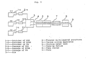
- cooling to a proper temperature by a method comprising using an extruder of high kneading and low heat generation type as shown in Figure 5, which is provided with a feed zone, a compression zone and a metering zone, and cooling at the exit side of the metering zone or cooling with a thermogenizer ( static mixer for cooling ) mounted on the polymer pass 2-A, and so on. Too rapid cooling will however cause a local supercooling promoting the local crystallization of PES, which would produce whitenings.
- the variation of the amount extruded be ⁇ 2.5 % or below, preferably ⁇ 1 % or below
- the variation of the polymer temperature be ⁇ 5°C or below, preferably ⁇ 3 ° C or below
- the pressure variation be ⁇ 4 % or below, preferably ⁇ 2 % or below.
- EVOH readily deteriorates by heat. At places of stagnation or of slow flow in the polymer pass, it will therefore show abnormal formations such as gels, foaming or coloring by degradation, which will mix into the EVOH polymer, leading to streaks or "grains" ( granular matters having mixed thereinto abnormal substances such as gels ). In particular, degraded matters deposited at the pass confluence inside the die are the principal cause of streak formation. To prevent the heat deterioration of EVOH, it is necessary in the first place to decrease the temperature of the polymer extruded.
- EVOH having a high viscosity or high barrier property having a low ethylene content
- a decrease in the extrusion temperature will decrease meltability in the extruder and lead to the formation of local nonmolten matters due to insufficient kneading.
- the unmolten polymer will then mix into the polymer flow, producing granular defects, or remain at deflected parts or at parts of low flow rate in the passage and form gel-like grains which again mix into the polymer, producing granular defects.
- the extrusion of TR it is important that the polymer extrusion be performed without forming irregular matters as in the case of PES and EVOH which requires the selection of appropriate extrusion conditions for the TR to be used. Of particular importance are the setting of the extrusion temperature and the balance between the extrusion temperature and the die temperature. If the TR temperature is too low as compared to that of the die temperature or the temperature of PES, the TR flow will show a temperature variation especially at the spiral mandrel, resulting in nonuniform thickness and streaks.
- the extrusion temperature of TR shall be selected, taking into consideration temperature balances with EVOH and PES.
- the standard temperature conditions are 255 to 285°C for PES at the die entrance ( 265 to 300°C at the highest temperature region of the extruder ), 220 to 260°C for EVOH at the die entrance, and 230 to 260°C as the set temperature for the die mold. Therefore, when the melting point of TR is 115°C, though the appropriate temperature range for molding TR is about 140 to about 180°C, the temperature of the die entrance is preferably set at 190 to 250°C for obtaining a good tube.
- FIG. 5 is an example of a representative flow sheet of a molding pro :as for preparing a 5-layered tube of the 3 resins PES/TR/EVOH and the manufacturing apparatus.
- 1-A, 1-B and 1-C are extruders each of which is provided with a feed zone, compression zone and a metering zone, for PES, EVOH and TR respectively.
- 2-A, 2-B and 2-C are passages of the three polymers, each of which is where necessary provided with a filter, a gear pump, a thermogenizer ( static mixer ), a purging valve, a temperature measuring device, an instrument for measuring the extrusion pressure, a heating and heat-insulation system, a cooling device, and so on.
- the die indicated by 3 is selected from many types, some of which are known from JPA 5750/1981 and JPA 147306/1985. The die conditions suitable for the present invention will be elucidated later.
- 4 designates a tubular multilayered structure in the process of having the die 3 and entering the sizing apparatus 5.
- 5 designates a vacuum sizing apparatus of the external cooling type, and 6 a tank for cooling water under atmospheric pressure.
- 7 is a take-up device of a representative top-and-bottom belts type for taking up the cooled and solidified tube and supplying it to a tube cutter 8.
- 8 designates a tube cutter which is a continuous tube cutter for cutting the running tube into short segments each corresponding to a bottle or into somewhat longer segments corresponding to a plurality of bottles.
- die The dies for molding a multilayered tube ( hereinafter referred to simply as "die") which is the most important device in the preparation of a multilayered tube, and its operating conditions will be explained hereinbelow.
- Known dies are as disclosed in JPA's 5750/1981 and 147306/1985. Similar dies are also known from JPA's 45369/1979, 102052/1976, 45163/1974, 127310/1986 and 212919/1983 and Japanese Patent Publication No. 29215/1983.
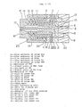
- Figure 6 shows an example of a die flow passage structure.
- Figure 6-(1) is a cross sectional view in the axial direction of the die.
- Figure 6-(2) shows the entering mandrel 23 constituting the die.
- 1 designates the flow entrance of the inner PES layer, 2 that of the inner TR layer, 3 that of EVOH, 4 that of the outer TR and 5 that of the outer PES.
- 6 is the entrance of PES, 7 the branch point of PES flow, 8 the entrance of TR, 9 the branch point of TR and 10 the entrance of EVOH.
- PES supplied to the entrances of the inner and outer PES layers 1 and 5 passes through the spiral passages of mandrels 21 and 25 for the inner and the outer PES layers respectively, while being circumferentially uniformly distributed, and passes to discharge slits 11 and 15 and finally to the confluence 16.
- TR supplied to the TR entrances 2 and 4 passes through spiral passages of mandrels 22 and 24 for TR, while being circumferentially uniformly distributed, and then passes to discharge slits 12 and 14 and finally to the confluence 16.
- EVOH is fed in a similar manner starting at the entrance 3.
- the tubular polymer flow comprising 5 layers of 3 different resins is formed, which then proceeds to the die discharging slit 17, and is extruded from the die to the sizing apparatus.
- 18 is a vent for supplying air to control the pressure inside the tube.
- 19 is a die cover, and 20 the material of the die flow passage.
- Figure 6(2) shows the entering mandrel for EVOH.
- the EVOH polymer supplied to the entrance of the EVOH layer is circumpherentially uniformly distributed by flow levelling along a spiral groove 3', and introduced into the EVOH discharge slit 13.
- the entrance passage 3 consists of a plurality of gates distributed evenly on a circumference so that the uniform flow levelling will be attained. The number of the gates depends on the diameter of the mandrel.
- the polymer flows to show almost no stagnation at the pas sages of each mandrel ( particularly in the spiral passages ) and distribute circumpherentially uniformly.
- the EVOH passage should be free from stagnation regions and of regions of slow flow.
- the average flow rate of EVOH is preferably 0.2 cm/sec or higher.
- the smoothness of the passages is also important.
- the EVOH passage is preferably plated with hard chromium, which is a metal having little tendency to deteriorate and to allow resin deposit to form when contacted closely with EVOH, having specular gloss with a surface roughness of 0.5 S or below, more preferably 0.1 S or below.
- discharge slits 11, 12, 13, 14 and 15 of each polymer leading to the confluence 16 The most important parts of the total system for achieving good moldings without streaks are the discharge slits 11, 12, 13, 14 and 15 of each polymer leading to the confluence 16.
- Preferred discharge slits must be smooth and flawless and have a slit gauge as narrow as possible to prevent the deposition of deteriorated matters which will cause streaks, must discharge uniformly and increase the rate of shear at the discharge.
- too narrow a slit will increase the extrusion pressure and also increase any variation in the slit gauge which would result in great thickness bias variations.
- the slit gauge is also restricted from the viewpoint of machining precision and assembling precision.
- the slit gauges are preferably 0.5 to 5 mm for PES, 0.2 to 1.2 mm for EVOH and 0.2 to 1.2 mm for TR, more preferably 0.8 to 3.0 mm for PES, 0.3 to 1.0 mm for EVOH and 0.3 to 1.0 mm for TR.
- the adjustment of the slit gauge of the die is also very important.
- the slit gauge is so adjusted that its variation is less than about ⁇ 3 %.
- the difference between maximum and minimum is less than about ⁇ 20 urn, more preferably ⁇ 10 u.m or below.
- the gauge of a discharge slit shall be designed to take the shear rate of the polymer as an important index, which is particularly important for the EVOH slit since the precipitation of deteriorated matters at the slit will greatly influence the formation of streaks.
- the die is a very important device which introduces each molten polymer into each extruder, distributes the polymer into a tubular polymer flow and then unites the flows to form a tubular multilayered polymer flow.
- the present inventors have prepared, and made a series of tests with dies of various forms and structures.
- a die having a spiral mandrel structure is most appropriate, and that it is very important, particularly in the case of EVOH, to provide the mandrel structure with a smooth passage to prevent stagnation and achieve a flow as smoothly as possible.
- the rate of shear at the exit of the discharge slit where the EVOH layer meets the TR layer and the PES layer is more than 30 sec preferably more than 50 sec. This is necessary because of the following fact: even in a smooth passage where no stagnation occurs, the viscosity of EVOH will increase when the rate of shear is low, at a region of slow flow on account of the thermal degradation of the EVOH. The flow rate will become slower, thus gelation will be promoted resulting in the deposition of degraded matters around the discharge slit. The deposit will grow gradually whereby the passage surface is deformed and minute nonuniformities of thickness are produced by the nonuniformity of the polymer flow, causing the formation of streaks.
- the shear rate of the EVOH passage surface must be high to prevent streak formation. Furthermore when a deformation or roughness caused by gelation appears once in the extrusion molding of EVOH, it is almost impossible to restore the original good condition by employing a purging agent or by adjusting the operation conditions. Rather it is necessary to complete disassemble and clean all passages from the extruder to the die, and to start then again.
- Figure 7(2) is a die where TR and PES of the outer layers and inner layers meet first and are laminated with each other, and finally the laminate meets the EVOH.
- Figure 7(3) is a die with a simultaneous confluence system in which the 5 layers meet at the same time.
- Figure 7(4) is a die in which EVOH and TR meet first and then PES joins from both sides. From the standpoint of confluence system die structures are basically divided into the above four systems.
- a suitable die for the purposes of the pre sent invention is any confluence system as it can perform streakless moldings if the structure of the passages (particularly of discharge slits and of confluence regions) is appropriate and the conditions for the polymers and the operation conditions (particularly, of starting up) are also appropriate. When the total difference in viscosity and temperature is great or under such difficult conditions as high speed molding with high output, dies having the confluence structures of (3) and (4) can perform molding operation more stably than those having structures (1) and (2).
- the EVOH When in the coextru sion molding of the multilayered tube utilizing high temperature PES and EVOH according to this invention, the EVOH invades another passage or when PES of high temperature and high viscosity mixes in the EVOH passage, the viscosity will increase and the stagnated EVOH will deteriorate because of the heat. The EVOH will thus remain and deposit in the passage,resulting in the formation of streaks or gel-like grains.
- An improvement is not expected by discharging and replacing the deteriorated matters by a conventional method of increasing the extrusion rate or by purging over a prolonged period.
- the starting method for the extrusion molding operation i.e. the state of the polymers which are introduced into the inside of the die is very important, and in particular the behavior of EVOH inside the die is most important.
- the starting method for the extrusion molding operation i.e. the state of the polymers which are introduced into the inside of the die is very important, and in particular the behavior of EVOH inside the die is most important.
- FIG. 13 is a diagram showing the flows and timing of the discharge of the polymers at the die for molding the tube of the present invention.
- the flow passages are those of the die shown in Figure 6-(1 In Figure 13(1), TR is first supplied from the entrances 2 and 4 and discharged to the confluence region to wet each passage surface, and on this timing EVOH is introduced from the entrance 3.
- the black area of A designates TR.
- This method comprises starting the molding by first extruding polymers having low viscosities and thereafter substituting them with normal polymers for molding.
- the method employed here is performed with the same polymers as those used for the molding, which have low viscosities; but a method using other polymers such as polyethylene (PE) and polypropyrene (PP) is also effective.
- PE polyethylene
- PP polypropyrene
- Polystyrene, nylon, high-modified PES, and the like are also useful as polymers to be substituted.
- the low viscosityEVOH used in this method is selected from grades having a good thermal stability.
- Further starting methods are methods including a method which comprises adjusting the extrusion rates of PES, EVOH and TR to obtain good flows, a method which comprises cooling and substituting the inside of the die and the polymer passages (particularly EVOH passage ) with an inert gas, and a method which comprises starting with polymers including PES, which can be extruded at a low temperature of 200 to 250°C.
- a bottle having good appearance, substantially no streaks and excellent gas barrier properties, pressure tightness, shock resistance and transparency can be obtained by making a preform from the multilayered tube having the above structure and subjecting it to biaxial blow molding.
- Defects in appearance which appear as continuous lines in the longitudinal direction on the bottle body, are longitudinal streaky irregularities. Each of these defects is caused by a nonuniform refraction of light through a resin lens formed by the irregularity in the thickness extending linearly in the longitudinal direction of the bottle body. This defect becomes a more distinct streak as it grows bigger and exceeds a certain size, and will show up on the bottle. The bottle loses its commercial value. The streaks of the bottle will further be elucidated below.
- the bottle having substantially no streaks as described herein, except for streaks originating from a shift of the matching planes of the mold or for streaks added for decoration purpose, is a bottle which has absolutely no longitudinally continuous region of optical nonuniformity caused by slight nonuniformities in the wall thickness or which has so invisible irregular streaks as not to detract from its appearance and not to make a person who uses it feel that the bottle is of inferior quality.
- Figure 1 shows a graph of thickness distribution circumferentially continuously measured on a specimen having an average thickness of 25 u.m of EVOH layer which specimen was taken from a circumpherence of the bottle body of a PES/EVOH multilayered bottle. Measurement of thickness was done on the specimen of EVOH layer being moved at a constant rate, by using a continuous thickness tester having a curved surface probe R 3 . Any instrument, however, can be used if it can measure local thicknesses with the same precision.
- the ordinate represents the thickness of the EVOH layer in urn
- the abscissa represents the circumferential distance of the bottle body in mm.
- Figure 1 shows that the thickness of the EVOH layer is not uniform.
- a bottle having substantially no streaks that is, a bottle which does not have so distinct a streak as to detract from its appearance and to lower its commercial value, does not show a portion having the above ratio of not less than 1/1000.
- a multilayered container is prepared from the multilayered tube of this invention as follows:
- any known method such as sequential blow molding or simultaneous blow molding can be employed.
- a suitable sequential blow molding method comprises drawing a parison, while inserting an extruding bar and blowing in a gas at a relatively low pressure, and then drawing it circumferentially while blowing in a gas at a relatively high pressure.
- a suitable simultaneous blow molding method comprises carrying out both circum ferential and axial drawings simultaneously while blowing in a gas at a high pressure. Suitable gases blown in during blow molding are air, nitrogen heated air, steam and the like.
- the axial drawing is performed for example by applying a drawing bar to the inside of the bottom of the parison and extending the drawing bar, while grasping the mouth of a parison with the mold and the mandrel.
- the drawing ratio in the axial direction be not less than 1.5 times the preform length and that in the circumferential ( radial ) direction be not less than 2.5 times the bottle diameter.
- the drawing ratio in the axial direction be not less than 1.5 times the preform length and that in the circumferential ( radial ) direction be not less than 2.5 times the bottle diameter.
- the radial drawing ratio is small, the drawing of the EVOH layer is insufficient and nonuniform drawing tend to occur, detracting from the bottle appearance and from the mechanical strength.
- the radial drawing ratio is higher than 3, uniform drawing can be achieved if there are no local thickness of other irregularities. Uniform drawing whereby streak formation is minimized which detracts from the appearance and the commercial value is possible with this ratio since the drawability is increased because the EVOH layer is co-drawn with the PES layers.
- the preferred range for the radial drawing ratio is 2.5 to 5.
- the preferred range of the axial drawing ratio is 1.5 to 5, and that of the total drawing ratio ( radial drawing ratio
- the preforms are heated at a temperature of 75 to 130°C. For obtaining a bottle of better appearance, heating at 80 to 125°C is preferred.
- the bottle thus obtained is substantially free from streaks and has not only a beautiful appearance but also excellent gas barrier properties. It is preferably used for foods, beverages, alcohols, particularly carbonated drinks and beers, as well as medicines and cosmetics.
- biaxial blow molding is mentioned as a representative example of molding of a multilayered tube
- a method which comprises drawing the obtained tube radially or both radially and axially to enlarge the tube diameter, cutting the enlarged tube to suitable lengths, and providing a stopper at both ends thereof to give a can-shaped container.
- extruder 1-A an extruder of the high kneading and low heat generation type, equipped with a cooling device on the delivery part of its metering zone was used.
- thermogenizer for cooling
- the variation of the output was ⁇ 1.5 % or below.
- the variation of the extrusion temperature was ⁇ 2°C or below.
- the variation of the extrusion pressure was ⁇ 2 % or below.
- extruder 1-B an extruder of the high kneading and low heat generation type which does not form stagnation was used.
- thermogenizer for cooling was mounted onto the polymer passage 2-B.
- the flow passage surface was plated with hard chromium and finished to specular gloss.
- the average flow rate of EVOH in the die was 1.2 cm/sec or higher.
- the rate of shear of EVOH in the die was 5 sec -1 .
- a die of the confluence system given in Figure 7(3) was employed as the co-extrusion die shown in Figure 5.
- the die for the extrusion of the 5 layered structure of 3 resins was assembled utilizing spigot joints and dowel pins, and the gauges of the slits for discharging the resins were checked over their entire circumference and adjusted to a tolerance of 50 mm or below for PET, 30 ⁇ m or below for the adhesive resin, 20 um or below for EVOH.
- the average gauge of each slit was adjusted to 2 mm, 1 mm and 1 mm for PET, EVOH and the adhesive resin respectively. The adjustment was done by adjusting bolts for the mandrel position mounted on the die.
- the melts extruded from the die were introduced through a sizing device 5 shown in Figure 5 (vacuum sizing device cooled externally ) and a cooling tank 6 ( atmospheric pressure ), taken up by a take-up apparatus 7 (top and bottom belts type ), and cut with a cutter 8 to the desired lengths to give tubes having an outer diameter of about 25 mm.
- a cross section of the tube comprising PET as the inner and outer layers, EVOH as the intermediate layer and adhesive resin layers between these two resin layers is shown in Figure 8.
- the thicknesses measured for each layer of the obtained tube are shown in Table 1.
- the tube comprising 5 layers of 3 different resins was cut into 1 cm pieces from which the EVOH layers were removed. After removing the adhesive resin sticking to the surface of the EVOH specimens by swelling with acetone, and drying, the EVOH layers were measured for minute thickness nonuniformities. The difference in thickness between any two points on the circumference of each of the two surfaces (cross sections) which were not less than 100 ⁇ m and not more than 500 um apart from each other was found to satisfy the following condition: The tube also satisfied the tube construction conditions of the formulae I- 1 to I-3, II, and IV -1 to 13.
- the tube was made into a preform by forming a mouth and a bottom on both ends using a laboratory preform molding machine ( LM-01, LM-02 ) made by KRUPP CORPOPLAST.
- the preform was then heated to 100°C and subjected to biaxial blow molding using a laboratory blow molding machine made by the same company at a drawing ratio of 10 ( axial drawing ratio x radial drawing ratio ) to give a bottle having a capacity of 0.5 I, a height of 17.5 cm and an outer diameter of 72 mm ⁇ .
- the thus obtained bottle was, as shown in Figure 9, of pleasant appearance having substantially no streaks.
- the average thickness construction of the layers of the bottle body is shown in Table 5.
- the lateral thickness distribution in the EVOH layer removed from the bottle body was as shown in Figure 11 and shows no thickness irregularity compared to Comparative Example 1 ( Figure 12 ) and no streaks at all which would detract from the bottle appearance.
- the thickness distribution was measured using a continuous film thickness tester made by ANRITSU ELECTRIC.
- the resins are subjected to co-extrusion molding, followed by vacuum sizing, cooling, taking up
- the assembling and adjustment of the die was carried out in the same manner as in Example 1 so that the gauges of the slits for discharging the resins were adjusted on the entire circumferences to tolerances of not more than 40 um, not more than 20 um and not more than 20 u.m for PET, EVOH and the adhesive resin respectively by adjusting bolts for the mandrel position mounted on the die.
- the average gauge of each slit was adjusted to 2 mm, 1 mm and 1 mm for PET, EVOH and the adhesive resin respectively. During the operation any change in the operating conditions was made gradually in order that the pressure inside the die would not change abruptly.
- the extrusion conditions for PET, EVOH and TR were the same as in Example 1 except for the extrusion temperature.
- the polymer passages 2-A, 2-B and 2-C were provided with purging valves and each polymer was discharged through it until a smooth extrusion was obtained. After the extrusion of each resin became steady, the purging valves were switched over successively to introduce TR, EVOH and PET in sequence at an appropriate timing into the die.
- the EVOH layers in the 1 cm specimens cut from the tubes were checked for thickness nonuniformity in the same manner as in Example 1.
- the difference in thickness between any two points on the circumference of each of the two cut surfaces ( cross sections ) which were not less than 100 u.m and not more than 500 um apart from each other was found to satisfy the condition II.
- the tube was made into a preform using the laboratory machine described in Example 1, and the preform was then molded into a blown bottle at a drawing ratio of 10 and at 95°C.
- the bottle obtained had a capacity of 0.5 I, a height of 17.5 cm and an outer diameter of 72 mm, and showed substantially no streaks detracting from the appearance of the bottle.
- the composition of PET and EVOH resins was different from those of Example 1, the proper selection of the resin viscosities and attention paid to consolidating the die and the change in the operating conditions led to a tube suitable for molding a bottle having an excellent appearance.
- EVOH MP: 179°C
- an adhesive resin a modified polyester resin bonded with aluminum atoms in an amount of 450 ppm and with benzoic acid, described in JPA 115,327/84; MP: 105°C
- the tubes obtained were molded using the blow molding machine described in Example 1 ( drawing ratio: 10, at 105°C) into bottles having a capacity of 0.5 1, a height of 17.5 cm and a diameter of 72 mm.
- Example 2 The same raw material chips as in Example 1 were subjected to tube molding, but the extrusion conditions for each resin and the order of introducing the resins into the die were changed.
- the extrusion of each resin was done in the same manner as in Example 1, except that the extrusion temperature for PET was 295°C, the extrusion temperature for EVOH was 295°C and the rate of shear of EVOH in the metering zone of the ex truder and that in the die were 18 sec and 21 sec - 1 respectively, and the extrusion temperature for TR was 180°C.
- the EVOH layer removed from the tube obtained showed a number of streaky thickness nonuniformities in a direction parallel to the tube axis.
- the EVOH layer ( cross sections cut at 1-cm intervals), there were observed not less than 13 spots in one cross section, and not less than a total of 26 spots in two cross sections.Thus this thickness nonuniformity between 2 points, 100 ⁇ m to 500 u.m apart from each other, does not satisfy the condition II.
- the tubes were molded with a machine described in Example 1 into preforms, which were then subjected to biaxial blow molding to give bottles having a capacity of 0.5 I. All of the bottles thus obtained, showed: clearly distinguishable streaks (S): 8 on average/bottle slightly distinguishable streaks : many and the bottle appearance was unappealing ( Figure 10 ). A bottle was selected at random from these bottles. The EVOH layer was removed and measured for its thickness distribution using the before-described continuous thickness tester. The result is shown in Figure 12. About 8 spots were found to show big difference in thickness and were thought to produce distinct streaks in the bottle.
- a PES having an [n] different from that in Example 1, a saponified product of an ethylene-vinyl acetate copolymer (EVOH ) having an ethylene content of 32 mol% and a saponification degree of 99.5 mol%, and an adhesive resin of similar kind to that in Example 2 were molded together into tubes with 5 layers of 3 different resins, the EVOH being the intermediate layer.
- the procedure was the same as in Example 1, except that at least one of the three resins had a MI at 250°C deviating from the preferred range.
- the results are shown in Table 3.
- the MI's of the resins used in each one of the Comparative Examples were as shown in Table 3: MI of EVOH in Comparative Example 2, Ml's of EVOH and PET in Comparative Example 3, Ml's of EVOH, PET and TR in Comparative Example 4, MI of TR in Comparative Example 5 and MI's of PET in Comparative Example 6 were not in the preferred range respectively.
- the EVOH layer was removed from each one of the tubes obtained and the cross sections cut at 1-cm intervals were checked with a micrometer. Among the thickness nonuniformities between any two points 100 um to 500 ⁇ m apart from each other, there were found not less than 4 spots in one cross section, and not less than 8 spots in two cross sections. Thus the number of these spots exceeds the maximum thickness-nonuniformity of condition II.
Landscapes
- Engineering & Computer Science (AREA)
- Mechanical Engineering (AREA)
- Manufacturing & Machinery (AREA)
- Laminated Bodies (AREA)
- Blow-Moulding Or Thermoforming Of Plastics Or The Like (AREA)
Applications Claiming Priority (2)
| Application Number | Priority Date | Filing Date | Title |
|---|---|---|---|
| JP28877/87 | 1987-02-09 | ||
| JP62028877A JPH082624B2 (ja) | 1987-02-09 | 1987-02-09 | 延伸成形用多層構造パイプおよびそれを用いた多層容器の製造法 |
Publications (3)
| Publication Number | Publication Date |
|---|---|
| EP0281776A2 true EP0281776A2 (de) | 1988-09-14 |
| EP0281776A3 EP0281776A3 (en) | 1990-05-16 |
| EP0281776B1 EP0281776B1 (de) | 1993-05-26 |
Family
ID=12260613
Family Applications (1)
| Application Number | Title | Priority Date | Filing Date |
|---|---|---|---|
| EP88101884A Expired - Lifetime EP0281776B1 (de) | 1987-02-09 | 1988-02-09 | Mehrschichtiges Rohr für das Formziehen und daraus hergestellter mehrschichtiger Behälter |
Country Status (7)
| Country | Link |
|---|---|
| US (1) | US4810542A (de) |
| EP (1) | EP0281776B1 (de) |
| JP (1) | JPH082624B2 (de) |
| AU (1) | AU591862B2 (de) |
| CA (1) | CA1301087C (de) |
| DE (1) | DE3881235T2 (de) |
| DK (1) | DK173434B1 (de) |
Cited By (2)
| Publication number | Priority date | Publication date | Assignee | Title |
|---|---|---|---|---|
| EP1029793A1 (de) * | 1999-02-18 | 2000-08-23 | Hanshin Kasei Co. Ltd. | Mehrschichtiger Behälter |
| EP1550541A1 (de) * | 2003-12-22 | 2005-07-06 | Kiefel Extrusion GmbH | Verfahren sowie Koextrusionsblaskopf zur Herstellung von Mehrschichtblasfolien |
Families Citing this family (11)
| Publication number | Priority date | Publication date | Assignee | Title |
|---|---|---|---|---|
| US5460625A (en) * | 1990-07-31 | 1995-10-24 | Baxter International Inc. | Cryogenic resistant coextruded tubing |
| US5274035A (en) * | 1991-12-30 | 1993-12-28 | Ferro Corporation | Ethylene vinyl acetate compositions and tubing made therefrom |
| US6109006A (en) * | 1998-07-14 | 2000-08-29 | Advanced Plastics Technologies, Ltd. | Process for making extruded pet containers |
| FR2813232B1 (fr) * | 2000-08-30 | 2002-10-11 | Commissariat Energie Atomique | Procede de fabrication d'une piece de revolution par rotomoulage et piece obtenue |
| FR2813235B1 (fr) * | 2000-08-30 | 2002-10-25 | Commissariat Energie Atomique | Structure et reservoir thermoplastique |
| KR20030027129A (ko) * | 2001-09-12 | 2003-04-07 | 김선홍 | 나선관과 나선관용 파이프 및 나선관용 파이프 제조장치 |
| DE10203626B4 (de) * | 2002-01-30 | 2004-01-08 | Veritas Ag | Mehrschichtiges Rohr bzw. Schlauch |
| DE502004007395D1 (de) * | 2003-06-11 | 2008-07-31 | Kautex Textron Gmbh & Co Kg | Extrusionsblasgeformtes einfüllrohr aus kunststoff |
| GB201303619D0 (en) * | 2013-02-28 | 2013-04-17 | Valpar Ind Ltd | Improved beverage dispensing tubing |
| US20150167887A1 (en) * | 2013-12-18 | 2015-06-18 | Illinois Tool Works Inc. | Methods and systems for jacket joints |
| AU2020379760A1 (en) * | 2019-11-04 | 2022-04-21 | Ring Container Technologies Llc | Container and method of manufacture |
Family Cites Families (7)
| Publication number | Priority date | Publication date | Assignee | Title |
|---|---|---|---|---|
| US4395221A (en) * | 1980-01-04 | 1983-07-26 | Mobil Oil Corporation | Tubular extrusion apparatus |
| US4436778A (en) * | 1981-10-05 | 1984-03-13 | Ball Corporation | Multilayer tubular body with uncentered barrier layer |
| JPS59136253A (ja) * | 1983-01-26 | 1984-08-04 | 東洋製罐株式会社 | 多層プラスチツク積層構造物 |
| JPS59143616A (ja) * | 1983-02-08 | 1984-08-17 | Toyo Seikan Kaisha Ltd | プラスチツク積層体の延伸方法 |
| US4564541A (en) * | 1983-02-08 | 1986-01-14 | Toyo Seikan Kaisha, Ltd. | Plastic laminate structure and vessel |
| US4649004A (en) * | 1983-12-27 | 1987-03-10 | Toyo Seikan Kaisha, Ltd. | Process for production of multi-layer pipes for draw-forming |
| JPS60247557A (ja) * | 1984-05-09 | 1985-12-07 | 株式会社クラレ | 積層体およびその製造方法 |
-
1987
- 1987-02-09 JP JP62028877A patent/JPH082624B2/ja not_active Expired - Fee Related
-
1988
- 1988-01-25 US US07/148,358 patent/US4810542A/en not_active Expired - Lifetime
- 1988-02-05 DK DK198800595A patent/DK173434B1/da not_active IP Right Cessation
- 1988-02-08 CA CA000558415A patent/CA1301087C/en not_active Expired - Lifetime
- 1988-02-08 AU AU11390/88A patent/AU591862B2/en not_active Ceased
- 1988-02-09 DE DE88101884T patent/DE3881235T2/de not_active Expired - Fee Related
- 1988-02-09 EP EP88101884A patent/EP0281776B1/de not_active Expired - Lifetime
Cited By (3)
| Publication number | Priority date | Publication date | Assignee | Title |
|---|---|---|---|---|
| EP1029793A1 (de) * | 1999-02-18 | 2000-08-23 | Hanshin Kasei Co. Ltd. | Mehrschichtiger Behälter |
| US6244454B1 (en) | 1999-02-18 | 2001-06-12 | Hanshin Kasei Co., Ltd. | Multilayer thin wall container |
| EP1550541A1 (de) * | 2003-12-22 | 2005-07-06 | Kiefel Extrusion GmbH | Verfahren sowie Koextrusionsblaskopf zur Herstellung von Mehrschichtblasfolien |
Also Published As
| Publication number | Publication date |
|---|---|
| JPH082624B2 (ja) | 1996-01-17 |
| CA1301087C (en) | 1992-05-19 |
| EP0281776B1 (de) | 1993-05-26 |
| EP0281776A3 (en) | 1990-05-16 |
| DK59588D0 (da) | 1988-02-05 |
| AU1139088A (en) | 1988-08-11 |
| DE3881235T2 (de) | 1993-12-16 |
| DE3881235D1 (de) | 1993-07-01 |
| JPS63194947A (ja) | 1988-08-12 |
| AU591862B2 (en) | 1989-12-14 |
| DK173434B1 (da) | 2000-10-23 |
| DK59588A (da) | 1988-08-10 |
| US4810542A (en) | 1989-03-07 |
Similar Documents
| Publication | Publication Date | Title |
|---|---|---|
| EP0281776B1 (de) | Mehrschichtiges Rohr für das Formziehen und daraus hergestellter mehrschichtiger Behälter | |
| US4741936A (en) | Laminate preform for a multi-layer polyester bottle | |
| EP0921928B1 (de) | Verfahren zum vermeiden von unkontrollierten polymerströmen im vorformhals beim verdichtungs- und kühlvorgang | |
| US4871410A (en) | Method of extruding and blow molding of gas-impermeable composite articles having water-resistant polyvinyl alcohol film layer | |
| US5035931A (en) | Multi-layer parison, multi-layer bottle and apparatus for and method of manufacturing parison and bottle | |
| MXPA02008369A (es) | Un proceso para formar un articulo coinyectado o coextruido de capas multiples. | |
| AU717374B2 (en) | Process for preparing thermoplastic polyolefin resin articles of reduced hydrocarbon permeability | |
| IE45933B1 (en) | Extrusion process for the manufacture of hollow bodies | |
| EP0076366B1 (de) | Mehrschichtiger Rohrkörper mit einer aussermittigen Sperrschicht | |
| AU2003200482B2 (en) | Coinjection Stretch Blow Molded Container | |
| EP0118227B1 (de) | Verfahren zum Strecken von Kunststofflaminaten | |
| EP0604239B1 (de) | Blasgeformte mehrschichtige Behälter mit ausgezeichnetem Oberflächenglanz sowie deren Herstellungsverfahren | |
| SE468381B (sv) | Flerskikts straeckt polyesterflaska samt foerfarande foer framstaellning daerav | |
| NZ215822A (en) | Extruding high density linear ethylene polymers to form heavy tubular members | |
| EP0167629B1 (de) | Gemischte harzzusammensetzung auf basis von polyamid und schmelzextrusionsformlinge daraus | |
| JPS6212023B2 (de) | ||
| JPS60215B2 (ja) | 二軸延伸ブロ−成形容器の製造法 | |
| JPS60147306A (ja) | 延伸成形用多層パイプの製造法 | |
| JPS6210811B2 (de) | ||
| JPH0436934B2 (de) | ||
| MXPA99001762A (en) | Method for preventing uncontrolled polymer flow in preform neck finish during packing and cooling stage | |
| JPS63120644A (ja) | 共射出中空成形多層容器 |
Legal Events
| Date | Code | Title | Description |
|---|---|---|---|
| PUAI | Public reference made under article 153(3) epc to a published international application that has entered the european phase |
Free format text: ORIGINAL CODE: 0009012 |
|
| AK | Designated contracting states |
Kind code of ref document: A2 Designated state(s): BE DE FR GB IT NL SE |
|
| PUAL | Search report despatched |
Free format text: ORIGINAL CODE: 0009013 |
|
| AK | Designated contracting states |
Kind code of ref document: A3 Designated state(s): BE DE FR GB IT NL SE |
|
| 17P | Request for examination filed |
Effective date: 19901023 |
|
| 17Q | First examination report despatched |
Effective date: 19911007 |
|
| GRAA | (expected) grant |
Free format text: ORIGINAL CODE: 0009210 |
|
| AK | Designated contracting states |
Kind code of ref document: B1 Designated state(s): BE DE FR GB IT NL SE |
|
| PG25 | Lapsed in a contracting state [announced via postgrant information from national office to epo] |
Ref country code: SE Effective date: 19930526 Ref country code: BE Effective date: 19930526 |
|
| REF | Corresponds to: |
Ref document number: 3881235 Country of ref document: DE Date of ref document: 19930701 |
|
| ET | Fr: translation filed | ||
| ITF | It: translation for a ep patent filed | ||
| PLBE | No opposition filed within time limit |
Free format text: ORIGINAL CODE: 0009261 |
|
| STAA | Information on the status of an ep patent application or granted ep patent |
Free format text: STATUS: NO OPPOSITION FILED WITHIN TIME LIMIT |
|
| 26N | No opposition filed | ||
| REG | Reference to a national code |
Ref country code: GB Ref legal event code: IF02 |
|
| PGFP | Annual fee paid to national office [announced via postgrant information from national office to epo] |
Ref country code: NL Payment date: 20030226 Year of fee payment: 16 |
|
| PG25 | Lapsed in a contracting state [announced via postgrant information from national office to epo] |
Ref country code: NL Free format text: LAPSE BECAUSE OF NON-PAYMENT OF DUE FEES Effective date: 20040901 |
|
| NLV4 | Nl: lapsed or anulled due to non-payment of the annual fee |
Effective date: 20040901 |
|
| PGFP | Annual fee paid to national office [announced via postgrant information from national office to epo] |
Ref country code: DE Payment date: 20050203 Year of fee payment: 18 |
|
| PGFP | Annual fee paid to national office [announced via postgrant information from national office to epo] |
Ref country code: FR Payment date: 20050208 Year of fee payment: 18 |
|
| PG25 | Lapsed in a contracting state [announced via postgrant information from national office to epo] |
Ref country code: IT Free format text: LAPSE BECAUSE OF NON-PAYMENT OF DUE FEES;WARNING: LAPSES OF ITALIAN PATENTS WITH EFFECTIVE DATE BEFORE 2007 MAY HAVE OCCURRED AT ANY TIME BEFORE 2007. THE CORRECT EFFECTIVE DATE MAY BE DIFFERENT FROM THE ONE RECORDED. Effective date: 20050209 |
|
| PGFP | Annual fee paid to national office [announced via postgrant information from national office to epo] |
Ref country code: GB Payment date: 20050209 Year of fee payment: 18 |
|
| PG25 | Lapsed in a contracting state [announced via postgrant information from national office to epo] |
Ref country code: GB Free format text: LAPSE BECAUSE OF NON-PAYMENT OF DUE FEES Effective date: 20060209 |
|
| PG25 | Lapsed in a contracting state [announced via postgrant information from national office to epo] |
Ref country code: DE Free format text: LAPSE BECAUSE OF NON-PAYMENT OF DUE FEES Effective date: 20060901 |
|
| GBPC | Gb: european patent ceased through non-payment of renewal fee |
Effective date: 20060209 |
|
| REG | Reference to a national code |
Ref country code: FR Ref legal event code: ST Effective date: 20061031 |
|
| PG25 | Lapsed in a contracting state [announced via postgrant information from national office to epo] |
Ref country code: FR Free format text: LAPSE BECAUSE OF NON-PAYMENT OF DUE FEES Effective date: 20060228 |