EP0281786A1 - Installationseinrichtung mit Infrarotsender - Google Patents
Installationseinrichtung mit Infrarotsender Download PDFInfo
- Publication number
- EP0281786A1 EP0281786A1 EP88102117A EP88102117A EP0281786A1 EP 0281786 A1 EP0281786 A1 EP 0281786A1 EP 88102117 A EP88102117 A EP 88102117A EP 88102117 A EP88102117 A EP 88102117A EP 0281786 A1 EP0281786 A1 EP 0281786A1
- Authority
- EP
- European Patent Office
- Prior art keywords
- flanks
- installation device
- different
- sectors
- transmitter diode
- Prior art date
- Legal status (The legal status is an assumption and is not a legal conclusion. Google has not performed a legal analysis and makes no representation as to the accuracy of the status listed.)
- Granted
Links
- 238000009434 installation Methods 0.000 claims abstract description 12
- 230000005855 radiation Effects 0.000 claims abstract description 5
Images
Classifications
-
- F—MECHANICAL ENGINEERING; LIGHTING; HEATING; WEAPONS; BLASTING
- F21—LIGHTING
- F21V—FUNCTIONAL FEATURES OR DETAILS OF LIGHTING DEVICES OR SYSTEMS THEREOF; STRUCTURAL COMBINATIONS OF LIGHTING DEVICES WITH OTHER ARTICLES, NOT OTHERWISE PROVIDED FOR
- F21V17/00—Fastening of component parts of lighting devices, e.g. shades, globes, refractors, reflectors, filters, screens, grids or protective cages
- F21V17/02—Fastening of component parts of lighting devices, e.g. shades, globes, refractors, reflectors, filters, screens, grids or protective cages with provision for adjustment
-
- F—MECHANICAL ENGINEERING; LIGHTING; HEATING; WEAPONS; BLASTING
- F21—LIGHTING
- F21V—FUNCTIONAL FEATURES OR DETAILS OF LIGHTING DEVICES OR SYSTEMS THEREOF; STRUCTURAL COMBINATIONS OF LIGHTING DEVICES WITH OTHER ARTICLES, NOT OTHERWISE PROVIDED FOR
- F21V5/00—Refractors for light sources
- F21V5/02—Refractors for light sources of prismatic shape
Definitions
- the invention relates to an installation device with an infrared transmitter, the radiation of which can be adjusted in the direction by a transmitter diode. It is known to provide pivotable housing attachments for this purpose. Swiveling attachments are, however, fixed to a radiation area determined by the swivel axis.
- the invention has for its object to develop an installation device of the type described, which is to be adjusted in its setting direction to all three coordinates of the room.
- the solution to the described problem is that the transmitter diode is followed in its beam path by a beam-deflecting body with sectors having different deflection behavior, the sectors of which can be adjusted to the transmitter diode.
- This also enables flat and aesthetically pleasing installation devices to be set up, and yet the direction of radiation can be freely adjusted to the room in a predetermined manner.
- the beam-deflecting body can in particular be a rotatably held disk with sectors of different deflection behavior, which is arranged off-center in the beam path of the transmitter diode. A sector with the desired deflection behavior can thus be brought into the beam path by rotation.
- the beam-deflecting body can have a sawtooth-like prism body on the beam incidence side form flanks of different steepness, the flanks of one side of which have a different angle of inclination or a different orientation from sector to sector. As a result, one sector brought into the beam path can bring about another desired deflection.
- the prism bodies can advantageously have a steep flank, approximately parallel to the angle of incidence, and flanks of the same inclination on their other side. In this way, the deflection behavior from the inclined flanks is clearly determined.
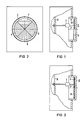
- the installation device has a transmitting diode 1, in the beam path 2 of which a beam-deflecting body 3 with sectors of different deflection behavior is connected.
- a sector or area can be brought into the beam path of the transmitter diode by the beam-deflecting body 3, so that it is adjusted to the transmitter diode.
- the beam-deflecting body 3 can be designed as a rotatably held disk or can also be in the form of a band.
- the transmitter diode 1 is excited by a circuit board 8 with a suitable electrical circuit. If the beam deflecting body is designed as a rotatably held disk, sectors 4, 5, 6 and 7 according to FIG. 2 can each have a different deflection ver hold have.
- the beam-deflecting body can form sawtooth-like prism bodies 9 according to FIG. 1 with flanks of different steepness on the beam incidence side.
- the flanks of one side can have a different angle of inclination or a different orientation from sector to sector. Understandably, the angle of inclination and the orientation can also be varied. It is also sufficient, in the case of uniformly designed prisms, to twist the disk z, as a result of which the alignment of the prisms with respect to the beam path changes. In relation to the beam path, one also obtains sectors of different deflection behavior.
- the prismatic bodies 9 of the beam-deflecting body 3 have a steep flank, approximately parallel to the incident beam, and on their other side in a sector flanks, each with the same inclination, the beam deflection can be determined particularly easily.
- the sector 7 has been attached into the beam path of the transmitter diode 1 by suitable rotation.
- the sector 4 of the beam-deflecting body 3 has been brought into the beam path.
- the beam can be deflected by reflection on the prism flanks or by rotation towards the denser medium.
Landscapes
- Engineering & Computer Science (AREA)
- General Engineering & Computer Science (AREA)
- Optical Communication System (AREA)
- Geophysics And Detection Of Objects (AREA)
- Organic Low-Molecular-Weight Compounds And Preparation Thereof (AREA)
- Facsimile Scanning Arrangements (AREA)
- Burglar Alarm Systems (AREA)
Abstract
Description
- Die Erfindung bezieht sich auf eine Installationseinrichtung mit Infrarotsender, dessen Abstrahlung von einer Sendediode sich in der Richtung einstellen läßt. Es ist bekannt, hierzu verschwenkbare Gehäuseanbauten vorzusehen. Verschwenkbare Anbauten sind jedoch auf einen durch die Schwenkachse bestimmten Abstrahlbereich festgelegt.
- Der Erfindung liegt die Aufgabe zugrunde, eine Installationseinrichtung der geschilderten Art zu entwickeln, die in ihrer Einstellrichtung auf alle drei Koordinaten des Raumes einzustellen ist.
- Die Lösung der geschilderten Aufgabe besteht nach der Erfindung darin, daß der Sendediode in ihrem Strahlengang ein strahlablenkenderKörper mit Sektroen unterschiedlichen Ablenkungsverhaltens nachgeschaltet ist, dessen Sektoren auf die Sendediode einstellbar sind. Dadurch lassen sich auch flache und ästhetisch ansprechende Installationseinrichtungen aufbauen und dennoch kann die Abstrahlrichtung in vorgegebener Weise frei auf den Raum eingestellt werden.
- Der strahlablenkende Körper kann insbesondere eine drehbar gehaltene Scheibe mit Sektoren unterschiedlichen Ablenkungsverhaltens sein, die außermittig im Strahlengang der Sendediode angeordnet ist. Ein Sektor mit dem gewünschten Ablenkungsverhalten kann so durch Drehung in den Strahlengang gebracht werden.
- Der strahlablenkende Körper kann auf der Strahleinfallseite im Querschnitt sägezahnartig Prismenkörper mit unterschiedlich steilen Flanken bilden, deren Flanken einer Seite von Sektor zu Sektor einen anderen Neigungswinkel oder eine andere Ausrichtung aufweisen. Dadurch kann je ein in den Strahlengang gebrachter Sektor eine andere gewünschte Ablenkung bewirken.
- Die Prismenkörper können vorteilhafterweise eine steile, in etwa zum Einfallswinkel parallele Flanke und auf ihrer anderen Seite Flanken jeweils gleicher Neigung aufweisen. Dadurch wird das Ablenkungsverhalten von den geneigten Flanken in übersichtlicher Weise bestimmt.
- Die Erfindung soll nun anhand eines in der Zeichnung grob schematisch wiedergegebenen Ausführungsbeispiels näher erläutert werden:
- In Fig. 1 ist eine Installationseinrichtung in Seitenansicht und teilweise geschnitten wiedergegeben.
- In Fig. 2 ist die Installationseinrichtung nach Fig. 1 in Aufsicht dargestellt.
- In Fig. 3 ist die Installationseinrichtung in der Ansicht nach Fig. 1 für ein anderes Ablenkungsverhalten veranschaulicht.
- Die Installationseinrichtung nach Fig. 1 weist eine Sendediode 1 auf, in deren Strahlengang 2 ein strahlablenkender Körper 3 mit Sektoren unterschiedlichen Ablenkungsverhaltens nachgeschaltet ist. Vom strahlenablenkenden Körper 3 kann ein Sektor oder Bereich in den Strahlengang der Sendediode gebracht werden, so daß er auf die Sendediode eingestellt ist. Der strahlablenkende Körper 3 kann als drehbar gehaltene Scheibe ausgebildet sein oder auch bandförmig sein. Die Sendediode 1 wird von einer Platine 8 mit geeigneter elektrischer Schaltung erregt. Wenn der strahlablenkende Körper als drehbar gehaltene Scheibe ausgebildet ist, können Sektoren 4, 5, 6 und 7 nach Fig. 2 jeweils ein anderes Ablenkungsver halten aufweisen. Hierzu kann der strahlablenkende Körper auf der Strahleinfallseite sägezahnartige Prismenkörper 9 nach Fig. 1 mit unterschiedlich steilen Flanken bilden. Die Flanken einer Seite können dabei von Sektor zu Sektor einen anderen Neigungswinkel oder eine andere Ausrichtung aufweisen. Verständlicherweise kann auch der Neigungswinkel und die Ausrichtung variiert werden. Es genügt auch, bei einheitlich ausgebildeten Prismen, die Scheibe z verdrehen, wodurch sich die Ausrichtung der Prismen, bezogen auf den Strahlengang, verändert. Dadruch erhält man, bezogen auf den Strahlengang, auch Sektoren unterschiedlichen Ablenkungsverhaltens.
- Wenn die Prismenkörper 9 des strahlablenkenden Körpers 3 eine steile, in etwa zum Einfallsstrahl parallele Flanke und auf ihrer anderen Seite in einem Sektor Flanken jeweils gleicher Neigung aufweisen, kann die Strahlablenkung besonders einfach bestimmt werden. In Fig. 1 ist der Sektor 7 in den Strahlengang der Sendediode 1 durch geeignetes Verdrehen angebracht worden. Im Zustand nach Fig. 3 ist beispielsweise der Sektor 4 des strahlablenkenden Körpers 3 in den Strahlengang gebracht worden.
- Die Strahlablenkung kann dabei durch Reflexion an den Prismenflanken oder durch Drehung zum dichteren Medium hin erfolgen.
Claims (4)
Priority Applications (1)
| Application Number | Priority Date | Filing Date | Title |
|---|---|---|---|
| AT88102117T ATE64773T1 (de) | 1987-02-27 | 1988-02-12 | Installationseinrichtung mit infrarotsender. |
Applications Claiming Priority (2)
| Application Number | Priority Date | Filing Date | Title |
|---|---|---|---|
| DE3706498 | 1987-02-27 | ||
| DE19873706498 DE3706498A1 (de) | 1987-02-27 | 1987-02-27 | Installationseinrichtung mit infrarotsender |
Publications (2)
| Publication Number | Publication Date |
|---|---|
| EP0281786A1 true EP0281786A1 (de) | 1988-09-14 |
| EP0281786B1 EP0281786B1 (de) | 1991-06-26 |
Family
ID=6321992
Family Applications (1)
| Application Number | Title | Priority Date | Filing Date |
|---|---|---|---|
| EP88102117A Expired - Lifetime EP0281786B1 (de) | 1987-02-27 | 1988-02-12 | Installationseinrichtung mit Infrarotsender |
Country Status (5)
| Country | Link |
|---|---|
| EP (1) | EP0281786B1 (de) |
| AT (1) | ATE64773T1 (de) |
| DE (2) | DE3706498A1 (de) |
| ES (1) | ES2022933B3 (de) |
| PT (1) | PT86833B (de) |
Families Citing this family (3)
| Publication number | Priority date | Publication date | Assignee | Title |
|---|---|---|---|---|
| DE3732233A1 (de) * | 1987-09-24 | 1989-04-13 | Siemens Ag | Installationseinrichtung mit infrarotsender |
| DE19532679A1 (de) * | 1995-09-05 | 1997-03-06 | Telefunken Microelectron | Optisches System |
| AT509563B1 (de) * | 2010-03-01 | 2015-10-15 | Hierzer Andreas | Leuchte mit lichtausrichtungselementen |
Citations (3)
| Publication number | Priority date | Publication date | Assignee | Title |
|---|---|---|---|---|
| GB418718A (en) * | 1933-02-10 | 1934-10-30 | Siemens Ag | Improvements relating to searchlights |
| GB806124A (en) * | 1955-02-25 | 1958-12-17 | Gen Electric Co Ltd | Improvements in or relating to electric lighting arrangements for indoor illumination |
| WO1985004704A1 (fr) * | 1984-04-09 | 1985-10-24 | Dr. Ing. Willing Gmbh | Phare d'eclairage avec reglage de la repartition de l'intensite lumineuse |
-
1987
- 1987-02-27 DE DE19873706498 patent/DE3706498A1/de not_active Withdrawn
-
1988
- 1988-02-12 EP EP88102117A patent/EP0281786B1/de not_active Expired - Lifetime
- 1988-02-12 ES ES88102117T patent/ES2022933B3/es not_active Expired - Lifetime
- 1988-02-12 AT AT88102117T patent/ATE64773T1/de not_active IP Right Cessation
- 1988-02-12 DE DE8888102117T patent/DE3863369D1/de not_active Expired - Lifetime
- 1988-02-25 PT PT86833A patent/PT86833B/pt not_active IP Right Cessation
Patent Citations (3)
| Publication number | Priority date | Publication date | Assignee | Title |
|---|---|---|---|---|
| GB418718A (en) * | 1933-02-10 | 1934-10-30 | Siemens Ag | Improvements relating to searchlights |
| GB806124A (en) * | 1955-02-25 | 1958-12-17 | Gen Electric Co Ltd | Improvements in or relating to electric lighting arrangements for indoor illumination |
| WO1985004704A1 (fr) * | 1984-04-09 | 1985-10-24 | Dr. Ing. Willing Gmbh | Phare d'eclairage avec reglage de la repartition de l'intensite lumineuse |
Also Published As
| Publication number | Publication date |
|---|---|
| PT86833A (pt) | 1989-02-28 |
| DE3863369D1 (de) | 1991-08-01 |
| EP0281786B1 (de) | 1991-06-26 |
| ATE64773T1 (de) | 1991-07-15 |
| PT86833B (pt) | 1993-08-31 |
| ES2022933B3 (es) | 1991-12-16 |
| DE3706498A1 (de) | 1988-09-08 |
Similar Documents
| Publication | Publication Date | Title |
|---|---|---|
| DE2410485C3 (de) | Prismensystem zur Farbtrennung in drei Farbkomponenten | |
| DE2952627C2 (de) | ||
| DE2446800A1 (de) | Niveliereinrichtung, insbesondere fuer bauzwecke | |
| EP0652422A2 (de) | Vorrichtung zum Empfang von Lichtstrahlen | |
| EP0113468A2 (de) | Optisches Bauelement zum Umlenken optischer Strahlen | |
| EP0956423B1 (de) | Sonnenschutzvorrichtung nach art einer jalousie | |
| EP1373966A1 (de) | Strahlformungsvorrichtung, anordnung zur einkopplung eines lichtstrahls in eine lichtleitfaser sowie strahldreheinheit für eine derartige strahlformungsvorrichtung oder eine derartige anordnung | |
| DE2732419C2 (de) | ||
| EP0144611B1 (de) | Strahlenteiler | |
| EP0281786B1 (de) | Installationseinrichtung mit Infrarotsender | |
| DE2633950C3 (de) | Szintillations-Gammakamera mit durch optische Streuelemente voneinander getrennten SzintillatorkristaUen | |
| DE19548338A1 (de) | Panzerscheibenaufbau für ein Sicherheitskraftfahrzeug | |
| DE765353C (de) | Lichtstrahlengitter fuer lichtelektrische Anlagen | |
| DE7710606U1 (de) | Signalleuchte fuer kraftfahrzeuge | |
| DE3390532C2 (de) | Optisches System zur mehrfachen Reflexion | |
| DE3923788C1 (de) | ||
| DE2727894A1 (de) | Verfahren zum herstellen von globoidschneckenraedern | |
| DE2548465A1 (de) | Tuersicherungs-lichtschranke | |
| DE2940345A1 (de) | Spektrum-konditioniervorrichtung | |
| DE2523643B2 (de) | Reflektor mit einstellbarem abstrahlwinkel | |
| DE4442228C1 (de) | Tageslicht-Beleuchtungsvorrichtung bestehend aus mindestens einer lichtleitenden Platte | |
| DE2946111C2 (de) | Optischer Körper für ein Cassegrain- oder cassegrain-ähnliches System | |
| DE3621961A1 (de) | Reflexlichtschranke zur beruehrungslosen nachfuehrung eines geraetes | |
| DE3525228A1 (de) | Optisches element | |
| DE3024693C2 (de) | Vorrichtung zum kraftschlüssigen Verbinden eines Rundholzes mit einem weiteren Rund- oder Vierkantholz in beliebiger Winkellage |
Legal Events
| Date | Code | Title | Description |
|---|---|---|---|
| PUAI | Public reference made under article 153(3) epc to a published international application that has entered the european phase |
Free format text: ORIGINAL CODE: 0009012 |
|
| AK | Designated contracting states |
Kind code of ref document: A1 Designated state(s): AT DE ES FR GB IT |
|
| 17P | Request for examination filed |
Effective date: 19890208 |
|
| 17Q | First examination report despatched |
Effective date: 19901010 |
|
| GRAA | (expected) grant |
Free format text: ORIGINAL CODE: 0009210 |
|
| AK | Designated contracting states |
Kind code of ref document: B1 Designated state(s): AT DE ES FR GB IT |
|
| REF | Corresponds to: |
Ref document number: 64773 Country of ref document: AT Date of ref document: 19910715 Kind code of ref document: T |
|
| REF | Corresponds to: |
Ref document number: 3863369 Country of ref document: DE Date of ref document: 19910801 |
|
| ET | Fr: translation filed | ||
| ITF | It: translation for a ep patent filed | ||
| GBT | Gb: translation of ep patent filed (gb section 77(6)(a)/1977) | ||
| PLBE | No opposition filed within time limit |
Free format text: ORIGINAL CODE: 0009261 |
|
| STAA | Information on the status of an ep patent application or granted ep patent |
Free format text: STATUS: NO OPPOSITION FILED WITHIN TIME LIMIT |
|
| 26N | No opposition filed | ||
| PGFP | Annual fee paid to national office [announced via postgrant information from national office to epo] |
Ref country code: GB Payment date: 19960122 Year of fee payment: 9 |
|
| PGFP | Annual fee paid to national office [announced via postgrant information from national office to epo] |
Ref country code: AT Payment date: 19960124 Year of fee payment: 9 |
|
| PGFP | Annual fee paid to national office [announced via postgrant information from national office to epo] |
Ref country code: ES Payment date: 19960216 Year of fee payment: 9 |
|
| PGFP | Annual fee paid to national office [announced via postgrant information from national office to epo] |
Ref country code: FR Payment date: 19960221 Year of fee payment: 9 |
|
| PGFP | Annual fee paid to national office [announced via postgrant information from national office to epo] |
Ref country code: DE Payment date: 19960419 Year of fee payment: 9 |
|
| PG25 | Lapsed in a contracting state [announced via postgrant information from national office to epo] |
Ref country code: GB Effective date: 19970212 Ref country code: AT Effective date: 19970212 |
|
| PG25 | Lapsed in a contracting state [announced via postgrant information from national office to epo] |
Ref country code: ES Free format text: LAPSE BECAUSE OF NON-PAYMENT OF DUE FEES Effective date: 19970213 |
|
| GBPC | Gb: european patent ceased through non-payment of renewal fee |
Effective date: 19970212 |
|
| PG25 | Lapsed in a contracting state [announced via postgrant information from national office to epo] |
Ref country code: FR Effective date: 19971030 |
|
| PG25 | Lapsed in a contracting state [announced via postgrant information from national office to epo] |
Ref country code: DE Effective date: 19971101 |
|
| REG | Reference to a national code |
Ref country code: FR Ref legal event code: ST |
|
| REG | Reference to a national code |
Ref country code: ES Ref legal event code: FD2A Effective date: 19990301 |
|
| PG25 | Lapsed in a contracting state [announced via postgrant information from national office to epo] |
Ref country code: IT Free format text: LAPSE BECAUSE OF NON-PAYMENT OF DUE FEES;WARNING: LAPSES OF ITALIAN PATENTS WITH EFFECTIVE DATE BEFORE 2007 MAY HAVE OCCURRED AT ANY TIME BEFORE 2007. THE CORRECT EFFECTIVE DATE MAY BE DIFFERENT FROM THE ONE RECORDED. Effective date: 20050212 |