EP0281935A2 - Dispositif pour le dosage d'un détergent dans une machine à laver la vaisselle - Google Patents
Dispositif pour le dosage d'un détergent dans une machine à laver la vaisselle Download PDFInfo
- Publication number
- EP0281935A2 EP0281935A2 EP88103249A EP88103249A EP0281935A2 EP 0281935 A2 EP0281935 A2 EP 0281935A2 EP 88103249 A EP88103249 A EP 88103249A EP 88103249 A EP88103249 A EP 88103249A EP 0281935 A2 EP0281935 A2 EP 0281935A2
- Authority
- EP
- European Patent Office
- Prior art keywords
- container
- housing
- cleaner
- front flap
- solid
- Prior art date
- Legal status (The legal status is an assumption and is not a legal conclusion. Google has not performed a legal analysis and makes no representation as to the accuracy of the status listed.)
- Granted
Links
- 239000003599 detergent Substances 0.000 title claims description 9
- 238000004851 dishwashing Methods 0.000 title 1
- XLYOFNOQVPJJNP-UHFFFAOYSA-N water Substances O XLYOFNOQVPJJNP-UHFFFAOYSA-N 0.000 claims abstract description 32
- 239000007921 spray Substances 0.000 claims abstract description 22
- 239000007787 solid Substances 0.000 claims abstract description 18
- 238000005507 spraying Methods 0.000 claims description 6
- 125000006850 spacer group Chemical group 0.000 claims description 2
- 238000004806 packaging method and process Methods 0.000 claims 2
- 238000004140 cleaning Methods 0.000 description 2
- 238000000034 method Methods 0.000 description 2
- ZAMOUSCENKQFHK-UHFFFAOYSA-N Chlorine atom Chemical compound [Cl] ZAMOUSCENKQFHK-UHFFFAOYSA-N 0.000 description 1
- 239000000969 carrier Substances 0.000 description 1
- 229910052801 chlorine Inorganic materials 0.000 description 1
- 239000000460 chlorine Substances 0.000 description 1
- 238000010276 construction Methods 0.000 description 1
- 238000003780 insertion Methods 0.000 description 1
- 230000037431 insertion Effects 0.000 description 1
- 238000004519 manufacturing process Methods 0.000 description 1
- 239000000463 material Substances 0.000 description 1
- 239000000843 powder Substances 0.000 description 1
- 239000013042 solid detergent Substances 0.000 description 1
- 239000000126 substance Substances 0.000 description 1
- 230000000007 visual effect Effects 0.000 description 1
Images

Classifications
-
- A—HUMAN NECESSITIES
- A47—FURNITURE; DOMESTIC ARTICLES OR APPLIANCES; COFFEE MILLS; SPICE MILLS; SUCTION CLEANERS IN GENERAL
- A47L—DOMESTIC WASHING OR CLEANING; SUCTION CLEANERS IN GENERAL
- A47L15/00—Washing or rinsing machines for crockery or tableware
- A47L15/42—Details
- A47L15/44—Devices for adding cleaning agents; Devices for dispensing cleaning agents, rinsing aids or deodorants
- A47L15/4436—Devices for adding cleaning agents; Devices for dispensing cleaning agents, rinsing aids or deodorants in the form of a detergent solution made by gradually dissolving a powder detergent cake or a solid detergent block
-
- B—PERFORMING OPERATIONS; TRANSPORTING
- B01—PHYSICAL OR CHEMICAL PROCESSES OR APPARATUS IN GENERAL
- B01F—MIXING, e.g. DISSOLVING, EMULSIFYING OR DISPERSING
- B01F21/00—Dissolving
- B01F21/20—Dissolving using flow mixing
- B01F21/22—Dissolving using flow mixing using additional holders in conduits, containers or pools for keeping the solid material in place, e.g. supports or receptacles
Definitions
- the invention relates to a device for the metered feeding of a solid-state cleaner in dissolved form in dishwashers, consisting of a housing accommodating the solid body with a closable opening, a water-spray device arranged on the bottom for loosening the cleaner and a drain for the loosened cleaner.
- Devices of the aforementioned structure are known (e.g. DE-GM 84 26 868). They usually consist of containers which are cylindrical or conical in cross-section and which have a water-permeable bottom in the lower region and into which the solid is introduced from above. The top of the container can be closed by means of a lid.
- a spray device in the form of one or more nozzles is arranged below the water-permeable, solid-receiving floor. The water leaving the nozzles is sprayed onto the solid from below and gradually dissolves it from below. The detergent dissolved in the water leaves the housing via a drain on the bottom in order to reach the dishwasher via a line.
- the dosing is carried out in such a way that the spraying device remains in operation as long as a cleaner is required in the dishwasher.
- the spray device is stopped, which is controlled, for example, by a measuring device in the dishwasher, the dissolving and feeding process is also stopped for a short time.
- a similar embodiment is also known for powdered cleaners (DE-PS 26 56 413), the housing having a sieve bottom which retains the powder above the spraying device.
- Such devices also mostly have control devices which, for example via control lamps, make the operating state visible to the outside. In order to obtain a clearly visible arrangement, these control devices must be attached to the front of the housing. Since these devices are generally mounted outside the dishwasher, if necessary also at least at a visual height on a wall of the room, it is difficult to load the container from above, since the container can often not be seen from above. On the other hand, the control device, which increases the overall depth of the container and thus hinders it, bothers.
- the block-shaped solid-state cleaner is accommodated in a cartridge which is inserted obliquely from above into the housing.
- the water spray device is inserted into the housing from behind and the water hits the sloping surface of the cleaner.
- the overall oblique arrangement of the housing makes it unnecessary Construction depth necessary and control devices can no longer be attached to the device.
- the invention has for its object to develop the device mentioned in such a way that loading of the housing with the solid-state cleaner is facilitated and the overall depth is reduced.
- the housing as a closure has a hinged front flap and this has an inwardly projecting water-permeable receptacle for the solid, and that the receptacle in the closed position of the front flap is arranged at a short distance above the spraying device.
- the housing thus has a flap arranged at the front, which can be swung open to the front, so that the container can be charged with the solid-state cleaner from the front in the region of the viewing height or below.
- the loading is further particularly simplified in that the solid-state cleaner is simply pushed onto the inside of the front flap with the receptacle and, after the front flap has been pivoted into the closed position, is held by the receptacle in the position desired for the release process.
- you close the front cover the device is immediately ready for use.
- any control and control device on the now closed ceiling of the housing, with which on the one hand control lamps can be arranged particularly visibly, since they are practically visible from all sides.
- the overall depth of the device can be reduced as this only must still be a little larger than the outline shape of the solid-state cleaner.
- the inside of the front flap has an open-topped container with a water-permeable bottom forming the receptacle.
- the solid-state cleaner can therefore be inserted directly into the container arranged on the front flap, so that after pivoting the front flap into the closed position it is in an exactly correct position with respect to the water spray device. Since the upper opening of the container is also located at the front in the open position of the front flap, loading is possible from the front, and the container can also be viewed, so any faults when inserting the solid-state cleaner are immediately noticeable. Any residues still present in the container, which could make loading difficult or impossible, can also be easily removed from the opening.
- the container is advantageously of the same shape as the housing, but with a smaller outline, so that the housing - with the exception of the control device - must have a volume that is only slightly larger than that of the solid-state cleaner itself.
- the container is expediently connected to the front flap via spacers in order to be able to manufacture it, for example, from a different material than the front flap forming the visible side of the housing.
- the bottom of the container is designed as a perforated plate in order to allow the water to enter freely from the spray device.
- the solid cleaner is accommodated in a can-like plastic container which tapers in a flat-conical manner on its upper side and has a short cylindrical neck for a screw cap.
- the solid cleaner is commercially available in this container. After removing the screw cap, the consumer inserts the fallen container into the housing of the metering device, the water being sprayed into the container by means of the spray device and the detergent being released from the container. The detergent runs off through the opening of the container into the lower part of the metering unit housing and can then be drained into the dishwasher.
- This known design of the device has the advantage in terms of occupational hygiene that the consumer no longer comes into contact with the cleaner. Another advantage is that the cleaner is properly packaged until the dosing device is inserted.
- a disadvantage is the fact that the cylindrical containers have a relatively large diameter, with the result that the metering device mounted on the wall or on the dishwasher has a correspondingly unfavorable projection. Furthermore, since the closure flap of the metering device forms the lid of the housing, the container must be inserted from above. The dosing device can only be inspected from above. This presupposes that the metering device is mounted at a correspondingly low height in order to be sufficiently accessible from an operational point of view. With regard to the arrangement of the control devices, the same applies as in the prior art described above.
- the object of the invention finds its solution in that the housing has a front flap hinged close to the floor and this has an inwardly projecting receptacle for the container with an opening for the passage of water, and in that the receptacle is in the closed position of the front flap is arranged at a short distance above the spray device.
- a further improvement, in particular with regard to the depth and space requirement, is achieved in that the container is designed as a rectangular bottle with an inwardly drawn neck having the opening, and in that the housing of the metering device has a rectangular shape adapted to the outline of the container.
- the housing is cuboid and the receptacles are set up for at least two containers arranged side by side.
- the advantages of the rectangular cross-section come into play to a particular degree, since the largest possible amount of cleaner can be made available in the smallest space. Rectangular, bottle-like containers are also more accessible than round, can-like containers with a relatively large diameter.
- a further advantageous embodiment is characterized in that the receptacles are formed by an intermediate floor arranged above the water spray device, which has at least two openings lying next to one another, the diameter of which is adapted to the diameter of the neck of the container, and that the water spray device is one of the Number of openings has a corresponding number of nozzles.
- the bottle-like containers with the solid cleaner are inserted with their neck first into the openings in the intermediate floor and are held there perfectly.
- a nozzle of the water spray device is assigned to each container, so that the cleaner is simultaneously discharged from all containers in a dissolved form.
- the front flap has the intermediate floor protruding into the housing near its lower edge.
- the intermediate shelf is thus moved out when the front flap is opened and brought into an angular position in which the insertion of the containers into the opening of the intermediate shelf is particularly simple.
- the containers used are then pivoted into their operating position when the front flap is closed.
- the front flap is articulated about a horizontal axis arranged approximately at the level of the water spraying device, so that the lower part of the housing acts as a tub which is closed on all sides and into which the detergent is removed can be formed.
- stops for limiting the pivoting angle of the front flap are arranged on the housing in the open position.
- the stops can be arranged on the inside of the opposite side walls of the housing and in the pivoting area of the intermediate floor, so that the intermediate floor runs into the stops in the open position of the front flap.
- the water spray device advantageously has a water pipe running in the longitudinal axis of the cuboid housing, into which the nozzles are interchangeably inserted.
- the nozzles can be selected so that the jet angle can be adapted to the opening of the container. Furthermore, if necessary, the nozzle can be easily removed for cleaning or replacement purposes.
- the intermediate base has side walls projecting upwards at least on its narrow sides in order to guide the containers used laterally and at the same time give the intermediate base the necessary stability.
- the container is preferably made of a UV-shielding plastic. This takes into account in particular the fact that solid cleaners contain chemical components that are not UV-resistant. These include, for example, chlorine carriers. Otherwise, the containers can be reused by returning them to the supplier of the cleaner and filling the containers there again with solid detergent.
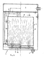
- the device shown in Figures 1 and 2 has a rectangular narrow housing 1, which is provided in the region of its bottom with a water connection 2 and a water outlet 3 and on its front side with a front flap 4, which at 5 in the area near the floor on a horizontal Axis, e.g. B. a hinge od. Like. Is hinged.
- the front flap has a handle bar 6 on its upper side.
- control device 7 On the ceiling of the housing 1 there is another housing part with a control device 7 which has, for example, a plurality of control lamps 8.
- a receptacle 9 in the form of a perforated plate is arranged in the area near the floor, which is arranged directly above a nozzle pipe 10 adjoining the water connection 2, which is arranged again extends from one narrow side to the other narrow side along the water-permeable receptacle 9.
- the water-permeable receptacle 9 forms the bottom of a container 11 with a front wall 12, rear wall 13 and side walls 14, which is attached to the inside of the front flap 4 at a distance from it and at a distance from it.
- the top of the container 16 is open.
- the cuboid-shaped solid-state cleaner which is not shown in the drawing, can be inserted through this opening 16 in the position shown in dash-dotted lines in FIG. 1 - the opening position - of the front flap 4.
- the bottom of the container 11 is located directly above the nozzle tube 10, so that the solid-state cleaner used is dissolved from below by the inflowing water.
- the detergent runs down through the floor and reaches outlet 3 through the dishwasher.
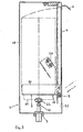
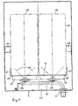
- FIGS. 3 and 4 differs from the one described above in that only the receptacle 9 is arranged on the front flap 4 and has two openings 17 arranged next to one another.
- a rectangular bottle-shaped container 18 with the neck 19 containing the solid cleaner can be inserted into these openings.
- the receptacle 9 in the manner of an intermediate floor is also attached to the lower edge of the front flap 4 in this exemplary embodiment, that is to say it can be pivoted together with the latter.
- the front flap 4 and the receptacle 9 can thus move from the position shown in solid lines in FIG. 2 into the position indicated by dash-dotted lines Position pivoted in which the container 18 can be inserted into the openings 17 of the receptacle 9 from the front.
- the opening position shown in broken lines is determined by stops 20 arranged inside the housing 1, against which the receptacle 9, which has 18 side cheeks 21 for holding the container, runs against these side cheeks.
- the neck 19 of the container 18 inserted into the receiving openings 17 engages over the nozzle 22 to a small extent.
- the water is sprayed from the nozzles 22 at an angle, which is, for example, about 90 degrees, through the neck 19 onto the solid cleaner located in the container 18, so that it is dissolved and the cleaning solution into the tub 23 and from there via the drain not shown reaches the dishwasher.
- the water spray device is controlled by a concentration sensor in the dishwasher.
Landscapes
- Chemical & Material Sciences (AREA)
- Chemical Kinetics & Catalysis (AREA)
- Washing And Drying Of Tableware (AREA)
- Detergent Compositions (AREA)
- Detail Structures Of Washing Machines And Dryers (AREA)
Priority Applications (1)
| Application Number | Priority Date | Filing Date | Title |
|---|---|---|---|
| AT88103249T ATE76730T1 (de) | 1987-03-12 | 1988-03-03 | Vorrichtung zum dosierten einspeisen eines reinigers in spuelmaschinen. |
Applications Claiming Priority (4)
| Application Number | Priority Date | Filing Date | Title |
|---|---|---|---|
| DE8703698U DE8703698U1 (de) | 1987-03-12 | 1987-03-12 | Vorrichtung zum dosierten Einspeisen eines Reinigers in Spülmaschinen |
| DE8703698U | 1987-03-12 | ||
| DE8710373U DE8710373U1 (de) | 1987-07-29 | 1987-07-29 | Vorrichtung zum dosierten Einspeisen eines Reinigers in Spülmaschinen |
| DE8710373U | 1987-07-29 |
Publications (3)
| Publication Number | Publication Date |
|---|---|
| EP0281935A2 true EP0281935A2 (fr) | 1988-09-14 |
| EP0281935A3 EP0281935A3 (en) | 1990-08-29 |
| EP0281935B1 EP0281935B1 (fr) | 1992-06-03 |
Family
ID=25951603
Family Applications (1)
| Application Number | Title | Priority Date | Filing Date |
|---|---|---|---|
| EP88103249A Expired - Lifetime EP0281935B1 (fr) | 1987-03-12 | 1988-03-03 | Dispositif pour le dosage d'un détergent dans une machine à laver la vaisselle |
Country Status (4)
| Country | Link |
|---|---|
| EP (1) | EP0281935B1 (fr) |
| AT (1) | ATE76730T1 (fr) |
| DE (1) | DE3871559D1 (fr) |
| ES (1) | ES2033352T3 (fr) |
Cited By (2)
| Publication number | Priority date | Publication date | Assignee | Title |
|---|---|---|---|---|
| EP0863084A1 (fr) * | 1997-03-06 | 1998-09-09 | CHEMISCHE FABRIK DR. WEIGERT (GMBH & CO.) | Kit et sachet-recharge pour le dosage d'une poudre |
| DE102006062910B4 (de) * | 2006-09-21 | 2014-05-08 | Witty Chemie Gmbh & Co. Kg | Vorrichtung und Verfahren zur Dosierung von Calciumhypochlorit in ein wäßriges System |
Family Cites Families (6)
| Publication number | Priority date | Publication date | Assignee | Title |
|---|---|---|---|---|
| US3727889A (en) * | 1970-05-21 | 1973-04-17 | Chapman Chem Co | Mixing method and apparatus |
| US4063663A (en) * | 1975-12-15 | 1977-12-20 | Economics Laboratory, Inc. | Powdered detergent dispenser |
| WO1980001160A1 (fr) * | 1978-12-05 | 1980-06-12 | Economics Lab | Distributeur de detergent en bloc solide |
| DE8426868U1 (de) * | 1984-09-12 | 1985-05-15 | Etol-Werk GmbH & Co KG Chemische Fabrik, 7603 Oppenau | Vorrichtung zum dosierten Einspeisen eines Feststoffreinigers in Spülmaschinen |
| DE3614621A1 (de) * | 1986-04-30 | 1987-11-05 | Puttfarcken Ulf | Reinigungsmittel-dosiervorrichtung fuer geschirrspueler |
| US4753781A (en) * | 1986-08-18 | 1988-06-28 | Beta Technology, Inc. | Solid detergent and chemical dispenser |
-
1988
- 1988-03-03 AT AT88103249T patent/ATE76730T1/de not_active IP Right Cessation
- 1988-03-03 EP EP88103249A patent/EP0281935B1/fr not_active Expired - Lifetime
- 1988-03-03 ES ES198888103249T patent/ES2033352T3/es not_active Expired - Lifetime
- 1988-03-03 DE DE8888103249T patent/DE3871559D1/de not_active Expired - Fee Related
Cited By (2)
| Publication number | Priority date | Publication date | Assignee | Title |
|---|---|---|---|---|
| EP0863084A1 (fr) * | 1997-03-06 | 1998-09-09 | CHEMISCHE FABRIK DR. WEIGERT (GMBH & CO.) | Kit et sachet-recharge pour le dosage d'une poudre |
| DE102006062910B4 (de) * | 2006-09-21 | 2014-05-08 | Witty Chemie Gmbh & Co. Kg | Vorrichtung und Verfahren zur Dosierung von Calciumhypochlorit in ein wäßriges System |
Also Published As
| Publication number | Publication date |
|---|---|
| EP0281935B1 (fr) | 1992-06-03 |
| DE3871559D1 (de) | 1992-07-09 |
| EP0281935A3 (en) | 1990-08-29 |
| ES2033352T3 (es) | 1993-03-16 |
| ATE76730T1 (de) | 1992-06-15 |
Similar Documents
| Publication | Publication Date | Title |
|---|---|---|
| DE68905970T2 (de) | Chemikalien-Ausgabegerät. | |
| DE69119912T2 (de) | Kontrollierte geschirrspülmittelfreigabe durch waschmittelbehälter | |
| DE3689145T2 (de) | Spender für Chemikalien in Blockform bei Reinigungssystemen. | |
| EP0254023B1 (fr) | Appareil pour remblayage et dosage | |
| DE2856005C2 (fr) | ||
| DE69303485T2 (de) | Reinigungsmittel-dosiervorrichtung | |
| DE69318572T2 (de) | Waschmittelspender | |
| DE2340390A1 (de) | Vorrichtung zum abgeben von nuessen und bonbons | |
| EP4003127A1 (fr) | Lave-vaisselle domestique | |
| EP0725592B1 (fr) | Systeme d'emballage et de dosage de detergents et autres produits chimiques pour le traitement de l'eau et/ou d'autres operations | |
| DE8018995U1 (de) | Geschirrspuelmaschine | |
| EP0281935B1 (fr) | Dispositif pour le dosage d'un détergent dans une machine à laver la vaisselle | |
| DE2946764C2 (fr) | ||
| EP3305970A1 (fr) | Appareil de dosage | |
| DE4140575A1 (de) | Zahnprothesen-reinigungsgeraet | |
| DE8710373U1 (de) | Vorrichtung zum dosierten Einspeisen eines Reinigers in Spülmaschinen | |
| DE3614621A1 (de) | Reinigungsmittel-dosiervorrichtung fuer geschirrspueler | |
| DE4421518A1 (de) | Vorrichtung zur Aufbewahrung und dosierten Abgabe von pulverförmigen und flüssigen Waschmitteln | |
| DE2736291C2 (de) | Dosiergerät für die Zugabe einer abgemessenen Flüssigkeitsmenge in den Spülraum, insbesondere einer Geschirrspülmaschine | |
| DE69209600T2 (de) | Reinigungsmittel-Dosiervorrichtung | |
| CH686702A5 (de) | Vorrichtung zum Auffangen von Kaffeesatz aus einem Abwasserstrom einer Kaffeemaschine. | |
| DE3418920C2 (fr) | ||
| CH329679A (de) | Vorrichtung zum Ausschenken bestimmter Flüssigkeitsmengen aus einem Behälter | |
| DE19646340A1 (de) | Verfahren und Vorrichtung zum Waschen von Feinwäsche | |
| DE8615861U1 (de) | Behälter mit Ausgabevorrichtung für Haushaltszwecke |
Legal Events
| Date | Code | Title | Description |
|---|---|---|---|
| PUAI | Public reference made under article 153(3) epc to a published international application that has entered the european phase |
Free format text: ORIGINAL CODE: 0009012 |
|
| AK | Designated contracting states |
Kind code of ref document: A2 Designated state(s): AT BE CH DE ES FR IT LI LU NL |
|
| PUAL | Search report despatched |
Free format text: ORIGINAL CODE: 0009013 |
|
| AK | Designated contracting states |
Kind code of ref document: A3 Designated state(s): AT BE CH DE ES FR IT LI LU NL |
|
| 17P | Request for examination filed |
Effective date: 19900727 |
|
| 17Q | First examination report despatched |
Effective date: 19911031 |
|
| GRAA | (expected) grant |
Free format text: ORIGINAL CODE: 0009210 |
|
| AK | Designated contracting states |
Kind code of ref document: B1 Designated state(s): AT BE CH DE ES FR IT LI LU NL |
|
| REF | Corresponds to: |
Ref document number: 76730 Country of ref document: AT Date of ref document: 19920615 Kind code of ref document: T |
|
| RAP2 | Party data changed (patent owner data changed or rights of a patent transferred) |
Owner name: TRIPP, URSULA Owner name: TRIPP, MARTINA |
|
| REF | Corresponds to: |
Ref document number: 3871559 Country of ref document: DE Date of ref document: 19920709 |
|
| ITF | It: translation for a ep patent filed | ||
| ET | Fr: translation filed | ||
| REG | Reference to a national code |
Ref country code: ES Ref legal event code: FG2A Ref document number: 2033352 Country of ref document: ES Kind code of ref document: T3 |
|
| PLBE | No opposition filed within time limit |
Free format text: ORIGINAL CODE: 0009261 |
|
| STAA | Information on the status of an ep patent application or granted ep patent |
Free format text: STATUS: NO OPPOSITION FILED WITHIN TIME LIMIT |
|
| 26N | No opposition filed | ||
| EPTA | Lu: last paid annual fee | ||
| PGFP | Annual fee paid to national office [announced via postgrant information from national office to epo] |
Ref country code: AT Payment date: 20050314 Year of fee payment: 18 |
|
| PGFP | Annual fee paid to national office [announced via postgrant information from national office to epo] |
Ref country code: NL Payment date: 20050317 Year of fee payment: 18 |
|
| PGFP | Annual fee paid to national office [announced via postgrant information from national office to epo] |
Ref country code: FR Payment date: 20050318 Year of fee payment: 18 |
|
| PGFP | Annual fee paid to national office [announced via postgrant information from national office to epo] |
Ref country code: DE Payment date: 20050322 Year of fee payment: 18 Ref country code: BE Payment date: 20050322 Year of fee payment: 18 |
|
| PGFP | Annual fee paid to national office [announced via postgrant information from national office to epo] |
Ref country code: LU Payment date: 20050325 Year of fee payment: 18 |
|
| PGFP | Annual fee paid to national office [announced via postgrant information from national office to epo] |
Ref country code: ES Payment date: 20050413 Year of fee payment: 18 |
|
| PGFP | Annual fee paid to national office [announced via postgrant information from national office to epo] |
Ref country code: CH Payment date: 20050603 Year of fee payment: 18 |
|
| PG25 | Lapsed in a contracting state [announced via postgrant information from national office to epo] |
Ref country code: AT Free format text: LAPSE BECAUSE OF NON-PAYMENT OF DUE FEES Effective date: 20060303 |
|
| PG25 | Lapsed in a contracting state [announced via postgrant information from national office to epo] |
Ref country code: ES Free format text: LAPSE BECAUSE OF NON-PAYMENT OF DUE FEES Effective date: 20060304 |
|
| PG25 | Lapsed in a contracting state [announced via postgrant information from national office to epo] |
Ref country code: LU Free format text: LAPSE BECAUSE OF NON-PAYMENT OF DUE FEES Effective date: 20060331 Ref country code: LI Free format text: LAPSE BECAUSE OF NON-PAYMENT OF DUE FEES Effective date: 20060331 Ref country code: CH Free format text: LAPSE BECAUSE OF NON-PAYMENT OF DUE FEES Effective date: 20060331 Ref country code: BE Free format text: LAPSE BECAUSE OF NON-PAYMENT OF DUE FEES Effective date: 20060331 |
|
| PGFP | Annual fee paid to national office [announced via postgrant information from national office to epo] |
Ref country code: IT Payment date: 20060331 Year of fee payment: 19 |
|
| PG25 | Lapsed in a contracting state [announced via postgrant information from national office to epo] |
Ref country code: NL Free format text: LAPSE BECAUSE OF NON-PAYMENT OF DUE FEES Effective date: 20061001 |
|
| PG25 | Lapsed in a contracting state [announced via postgrant information from national office to epo] |
Ref country code: DE Free format text: LAPSE BECAUSE OF NON-PAYMENT OF DUE FEES Effective date: 20061003 |
|
| REG | Reference to a national code |
Ref country code: CH Ref legal event code: PL |
|
| NLV4 | Nl: lapsed or anulled due to non-payment of the annual fee |
Effective date: 20061001 |
|
| REG | Reference to a national code |
Ref country code: FR Ref legal event code: ST Effective date: 20061130 |
|
| REG | Reference to a national code |
Ref country code: ES Ref legal event code: FD2A Effective date: 20060304 |
|
| BERE | Be: lapsed |
Owner name: *ETOL-WERK CHEMISCHE FABRIK EBERHARD TRIPP G.M.B.H Effective date: 20060331 |
|
| PG25 | Lapsed in a contracting state [announced via postgrant information from national office to epo] |
Ref country code: FR Free format text: LAPSE BECAUSE OF NON-PAYMENT OF DUE FEES Effective date: 20060331 |
|
| PG25 | Lapsed in a contracting state [announced via postgrant information from national office to epo] |
Ref country code: IT Free format text: LAPSE BECAUSE OF NON-PAYMENT OF DUE FEES Effective date: 20070303 |