EP0281966A2 - Thermischer Leitfähigkeitsdetektor - Google Patents
Thermischer Leitfähigkeitsdetektor Download PDFInfo
- Publication number
- EP0281966A2 EP0281966A2 EP88103409A EP88103409A EP0281966A2 EP 0281966 A2 EP0281966 A2 EP 0281966A2 EP 88103409 A EP88103409 A EP 88103409A EP 88103409 A EP88103409 A EP 88103409A EP 0281966 A2 EP0281966 A2 EP 0281966A2
- Authority
- EP
- European Patent Office
- Prior art keywords
- sample
- cell
- improvement
- block
- chamber
- Prior art date
- Legal status (The legal status is an assumption and is not a legal conclusion. Google has not performed a legal analysis and makes no representation as to the accuracy of the status listed.)
- Granted
Links
Images



Classifications
-
- G—PHYSICS
- G01—MEASURING; TESTING
- G01N—INVESTIGATING OR ANALYSING MATERIALS BY DETERMINING THEIR CHEMICAL OR PHYSICAL PROPERTIES
- G01N30/00—Investigating or analysing materials by separation into components using adsorption, absorption or similar phenomena or using ion-exchange, e.g. chromatography or field flow fractionation
- G01N30/02—Column chromatography
- G01N30/62—Detectors specially adapted therefor
- G01N30/64—Electrical detectors
- G01N30/66—Thermal conductivity detectors
-
- G—PHYSICS
- G01—MEASURING; TESTING
- G01N—INVESTIGATING OR ANALYSING MATERIALS BY DETERMINING THEIR CHEMICAL OR PHYSICAL PROPERTIES
- G01N27/00—Investigating or analysing materials by the use of electric, electrochemical, or magnetic means
- G01N27/02—Investigating or analysing materials by the use of electric, electrochemical, or magnetic means by investigating impedance
- G01N27/04—Investigating or analysing materials by the use of electric, electrochemical, or magnetic means by investigating impedance by investigating resistance
- G01N27/14—Investigating or analysing materials by the use of electric, electrochemical, or magnetic means by investigating impedance by investigating resistance of an electrically-heated body in dependence upon change of temperature
- G01N27/18—Investigating or analysing materials by the use of electric, electrochemical, or magnetic means by investigating impedance by investigating resistance of an electrically-heated body in dependence upon change of temperature caused by changes in the thermal conductivity of a surrounding material to be tested
Definitions
- the field of this invention is that of detectors for use in analytical chemical instruments. More particularly, detectors for use in gas chromatographs; carbon, hydrogen, nitrogen, (CHN) elemental analyzers, and the like.
- the present invention is an improvement of that disclosed in the above-referenced patent. Specifically, the sensing and reference elements are given improved protection against short term fluctuations in the surrounding temperature, against flow rate changes in the sample and reference gases, and against leaks. Also, construction materials having significant vapor pressures are avoided. These changes permit the employment of carrier gases such as argon whose thermal conductivity is only slightly different from that of the sample gases. The resulting signals are relatively weak and are electronically amplified.
- the sensing elements are symmetrically disposed in a metal block of high thermal conductivity.
- the block is suspended in a housing, the space between being purged with an inert gas such as the carrier.
- Sintered plugs in the sample and reference flow paths within the block isolate the elements from the gas flow path, but do not prevent their rapid response to changes in the gas components.
- a deliberate heat leak is provided to control the thermal time constant of the cell.
- Electrical feedthroughs are potted in thermally conductive resin, further to immunize the detector against temperature gradients.
- FIG. 1 there is illustrated a gas chromatograph employing the detector of this invention.
- a sample to be analyzed is derived from the sample source 10 and introduced into the chromatographic column 12 through an injector block 14.
- Carrier gas such as argon or helium, is supplied from a source 16 to the injector block 14.
- the sample which is vaporized by insertion into the heated injector block, is carried by the carrier gas through a tube 18 to the column 12.
- the column 12 causes the constituents of the sample to separate and successively elute from the column.
- Detector 22 includes electrical sensing elements responsive, respectively, to the sample/carrier from column 12 and to a reference gas.
- the carrier gas may function as the reference gas for the detector and is introduced to the detector through tube 24.
- a vent 26 exhausts the carrier gas and sample to atmosphere, and a vent 28 similarly exhausts the reference gas.
- the sensing elements in the detector 22 are connected in a bridge circuit 30 whose amplified output is supplied to a recorder 32.
- FIGS. 2 and 3 illustrate a detector in accordance with the present invention which achieves this objective. It comprises a housing 33 which includes a circular base 34 having a central boss 36. Surrounding the boss 36 is an annular gasket 38. Positioned atop the gasket 38 is a cylindrical aluminum cylinder 40. Mounted atop the cylinder 40 is a second annular gasket 42 which provides a seal for a cover 44. Together the base 36, cylinder 40, and cover 44 form a housing for a cell 46 mounted therein. A fitting 48 through the cylinder 40 connects to a tube 50 for injecting an inert gas, which may be the carrier, into the interior of the housing 33.
- an inert gas which may be the carrier
- the cell 46 is a cylindrical block of copper which is positioned within the housing by four copper wires 52. These wires create a deliberate heat leak which controls the thermal time constant of the cell 46.
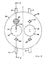
- the construction of cell 46 will be best appreciated from the following description taken in connection with FIGS. 5 and 6.
- Cell 46 comprises a cylindrical copper block 54.
- a skirt 56 around the bottom edge of the block 54 defines openings 58 which may be used to support the heat leak wires 52 previously described.
- the block 54 defines a pair of symmetrically located cylindrical chambers, a sample chamber 60 as shown in FIG. 6 and a reference chamber which is identical and is accordingly not illustrated.
- a sample gas passage 62 passes through the chamber 60 and is connected to a sample inlet tube 64 and a sample outlet tube 66.
- the sample inlet tube 64 is connected through the cover 44 of the housing to a sample inlet fitting 68 (FIG. 3) which would normally connect to the tube 20 shown in FIG. 1.
- the sample outlet tube 66 is connected through the cover 44 to a sample vent fitting 70.
- the reference chamber connects in a similar fashion through inlet tube 71 to reference input fitting 72 and through outlet tube 73 to reference vent fitting 74 (FIG. 3).
- the cover 44 of the housing 33 also carries a vent fitting 75 to the interior of the housing.
- a plug 76 of sintered silver is directly in the path of gases passing through passage 62.
- the plug 76 may typically be 50% porous and have a pore size equal to, or greater than, 20 microns. It is press-fitted, and thereby thermally clamped, into the copper block 54.
- FIG. 6 the upper end of the chamber 60 is widened to create an annular seat 78.
- the detail of FIG. 7 shows it prior to welding.
- the seat is surrounded by a tapered annular ring 80 of copper.
- a cylindrical well 82 extends from the upper surface of the block 54 and surrounds the tapered ring 80.
- the thermistor assembly 84 comprises a generally cylindrical eyelet 86 having a flange 88 which rests upon the seat 78 surrounding the upper end of the chamber 60.
- the eyelet 86 is of gold-flashed KOVAR (a Westinghouse trademark).
- KOVAR gold-flashed KOVAR
- Secured within the eyelet 86 by means of a glass fill 90 are a pair of gold-flashed KOVAR leads 92.
- the leads 92 extend from above the upper surface of block 54 to below the lower surface of eyelet 86 where they are spread as shown in FIG. 6. Supported between their lower ends is a platinum alloy lead 94 which supports a thermistor bead 96.
- the reference chamber contains a thermistor assembly substantially identical to thermistor assembly 84. These assemblies must be hermetically sealed into their respective chambers. However, it is desirable to avoid the use of materials such as elastomers or cements which possess even slight vapor pressure or might deteriorate with time. Electron beam welding in vacuo produces a clean permanent seal between the copper block 54 and the flange 88 of the thermistor beam assembly 84.
- the seat design illustrated in detail in FIG. 7 permits rapid local heating and fusion of the copper at the seal without undue heating of the entire block and thermistor (whose temperature should not exceed 300°C).
- the upper surface of the block 54 is drilled and tapped to provide four threaded holes 102. Threaded into these holds are four standoffs 104. These provide terminals 106 which are connected to the thermistor leads 92 by means of copper wire 108. Electrical conductors 110 (FIG. 2) bring the thermistor outputs through the cover 44 of the aluminum housing via a header assembly 112.
- the thermistor elements are symmetrically disposed in a copper block 54 which is suspended in an outer chamber formed by the housing 33.
- the space between the housing and the block is purged with carrier gas which is admitted through the connector 48 and exits through the vent 75.
- the sintered plugs 76 are thermally clamped to the copper block 54. Accordingly, each presents a surface to its thermistor chamber whose temperature is constant and substantially unaffected by the rate of flow of gas through the detector. Their porosity is such that diffusion is not seriously inhibited and the composition of the gas surrounding the thermistor bead is rapidly representative of that in the flow stream.
- the flow might typically decay from 0.7 cc per second to 0.6 cc per second over the course of one analytical cycle. It is desirable that the base line require no correction for flow sensitivity and that signals be due only to change in gas composition.
- a deliberate heat leak may be provided, especially in the case of argon, by the use of the wires 52 to control the thermal time constant of the cell. Electron beam welding and fluxless vacuum brazing are employed in joining operations. Feedthroughs for the thermistor elements are potted in thermally conductive epoxy.
- the entire detector assembly rests in a thermostatically controlled, high velocity air bath which is not a feature of this invention.
- the average temperature of the bath is precisely controlled.
- the turbulence and line voltage perturbations may cause rapid small fluctuations which are effectively filtered by the assembly.
- the copper block 54 had a diameter of 1" and a length of 1".
- the sample and reference chambers were each approximately 0.157" in diameter.
- the thermistor assemblies were as described above. They were matched as to resistance, voltage, and current.
- Each of the porous silver plugs 76 had a length of 0.19" and a diameter of 0.160".
- the diameter of the eyelet 86 of thermistor assembly 84 was .130".
- the angle ⁇ of seat 78 was 4°, which matched the similar angle of the bottom of the flange 88 of the thermistor assembly.
- the thickness x of the ring 80 was .015-.020".
- the well 82 and the corresponding well 98 for the reference chamber were filled with an epoxy casting resin 100 such as CASTALL 301 which has a relatively high thermal conductivity.
- FIG. 8 Illustrated in FIG. 8 is a bridge circuit including sensing thermistor 96 and reference thermistor 114.
- Input terminal 116 might be connected to 19 volts for a helium carrier and 12 volts for an argon carrier.
- Output terminals 118, 120 are connected to a recorder amplifier.
- the cell When helium is employed as a carrier gas, the cell is effectively coupled thermally to the case by gaseous conduction. The rise in temperature of the cell due to power dissipated in the thermistors is negligible.
- argon When argon is used as a carrier, it has been found advantageous to employ the heat leaks previously described. These are the copper wires 52 between the cell and the inner wall of the housing. They permit reasonable rapid equilibration on start up and negligible temperature self-rise.
- the heat capacity of the cell is about 10 calorie/k and the thermal resistance of four 2 centimeter lengths of .063" diameter copper wire in parallel is about 25 cgs units. This gives an RC thermal time constant of approximately four minutes which is a good compromise between effective filtering and rapid equilibration.
Landscapes
- Chemical & Material Sciences (AREA)
- General Health & Medical Sciences (AREA)
- Immunology (AREA)
- Health & Medical Sciences (AREA)
- Analytical Chemistry (AREA)
- Biochemistry (AREA)
- Physics & Mathematics (AREA)
- General Physics & Mathematics (AREA)
- Life Sciences & Earth Sciences (AREA)
- Pathology (AREA)
- Chemical Kinetics & Catalysis (AREA)
- Electrochemistry (AREA)
- Investigating Or Analyzing Materials By The Use Of Electric Means (AREA)
- Investigating Or Analyzing Materials Using Thermal Means (AREA)
- Analysing Materials By The Use Of Radiation (AREA)
Applications Claiming Priority (2)
| Application Number | Priority Date | Filing Date | Title |
|---|---|---|---|
| US22147 | 1987-03-05 | ||
| US07/022,147 US4813267A (en) | 1987-03-05 | 1987-03-05 | Thermal conductivity detector |
Publications (3)
| Publication Number | Publication Date |
|---|---|
| EP0281966A2 true EP0281966A2 (de) | 1988-09-14 |
| EP0281966A3 EP0281966A3 (de) | 1991-02-20 |
| EP0281966B1 EP0281966B1 (de) | 1994-02-02 |
Family
ID=21808055
Family Applications (1)
| Application Number | Title | Priority Date | Filing Date |
|---|---|---|---|
| EP88103409A Expired - Lifetime EP0281966B1 (de) | 1987-03-05 | 1988-03-04 | Thermischer Leitfähigkeitsdetektor |
Country Status (4)
| Country | Link |
|---|---|
| US (1) | US4813267A (de) |
| EP (1) | EP0281966B1 (de) |
| JP (1) | JP2683012B2 (de) |
| DE (1) | DE3887541T2 (de) |
Cited By (4)
| Publication number | Priority date | Publication date | Assignee | Title |
|---|---|---|---|---|
| EP0433741A1 (de) * | 1989-12-04 | 1991-06-26 | Rosemount GmbH & Co. | Verfahren und Vorrichtung zur Detektion von fluidischen, insbesondere gasförmigen oder flüssigen Medien, die nach dem Prinzip der Wärmeleitfähigkeit arbeiten |
| DE4005131A1 (de) * | 1990-02-17 | 1991-08-22 | Rosemount Gmbh & Co | Messzelle fuer einen waermeleitfaehigkeits-analysator |
| EP0529295A1 (de) * | 1991-08-22 | 1993-03-03 | The Perkin-Elmer Corporation | Thermischer Leitfähigkeitsdetektor mit einem Element |
| EP0382414B1 (de) * | 1989-02-06 | 1995-01-11 | Alcan International Limited | Verfahren und Vorrichtung zur Messung der Wärmeleitfähigkeit von Gasen |
Families Citing this family (8)
| Publication number | Priority date | Publication date | Assignee | Title |
|---|---|---|---|---|
| US4970891A (en) * | 1989-12-26 | 1990-11-20 | Ethyl Corporation | Apparatus for measuring gaseous impurity in solids |
| JPH0416358U (de) * | 1990-05-31 | 1992-02-10 | ||
| DE4107295A1 (de) * | 1991-03-07 | 1992-09-10 | Manfred Dr Rer Nat Ritschel | Verfahren zur bestimmung von chemischen und/oder physikalischen eigenschaften einer gasatmosphaere |
| US5535614A (en) * | 1993-11-11 | 1996-07-16 | Nok Corporation | Thermal conductivity gas sensor for measuring fuel vapor content |
| US6502983B2 (en) * | 1999-03-30 | 2003-01-07 | The Regents Of The University Of California | Micro-machined thermo-conductivity detector |
| WO2004068134A1 (en) * | 2003-01-29 | 2004-08-12 | Agilent Technologies, Inc. | Apparatus and method for thermal conductivity detection in gas chromatography equipment |
| US7347080B2 (en) * | 2005-12-23 | 2008-03-25 | Serveron Corporation | Thermal conductivity detector |
| CN110554125A (zh) * | 2018-05-31 | 2019-12-10 | 滕州市滕海分析仪器有限公司 | 一种热导检测器和柱室及其安装工艺 |
Family Cites Families (13)
| Publication number | Priority date | Publication date | Assignee | Title |
|---|---|---|---|---|
| US3097520A (en) * | 1963-07-16 | Reducing thermal upsets in fluid measuring cells | ||
| DE465367C (de) * | 1925-08-09 | 1928-09-15 | Hartmann & Braun Akt Ges | Elektrischer Gasgemischpruefer |
| US2585959A (en) * | 1949-01-24 | 1952-02-19 | Minter Instr Corp | Thermal conductivity bridge for gas analysis |
| US2687036A (en) * | 1950-11-20 | 1954-08-24 | Minter Instr Corp | Thermal conductivity bridge-block |
| GB1116315A (en) * | 1966-04-04 | 1968-06-06 | Nat Res Dev | Improvements in or relating to apparatus for the detection of gases |
| US3607084A (en) * | 1968-12-02 | 1971-09-21 | Sun Electric Corp | Combustible gas measurement |
| US3687631A (en) * | 1969-06-03 | 1972-08-29 | Scott Research Lab Inc | Method and equipment for catalytic analysis of gases |
| US3603134A (en) * | 1970-03-02 | 1971-09-07 | Perkin Elmer Corp | Detector arrangements for analytical apparatus |
| US3791195A (en) * | 1972-09-21 | 1974-02-12 | W Loe | Thermal conductivity element |
| JPS591217Y2 (ja) * | 1976-09-30 | 1984-01-13 | 株式会社リコー | 電子写真複写機 |
| US4226112A (en) * | 1978-01-30 | 1980-10-07 | Gomidas Jibelian | Method and apparatus for analyzing gases |
| GB2042734A (en) * | 1979-02-16 | 1980-09-24 | Coal Ind | Gas Detection Apparatus |
| GB2091882B (en) * | 1981-01-26 | 1985-05-01 | Nat Res Dev | Electrical catalytic gas detection systems |
-
1987
- 1987-03-05 US US07/022,147 patent/US4813267A/en not_active Expired - Fee Related
-
1988
- 1988-03-04 EP EP88103409A patent/EP0281966B1/de not_active Expired - Lifetime
- 1988-03-04 JP JP63049955A patent/JP2683012B2/ja not_active Expired - Lifetime
- 1988-03-04 DE DE88103409T patent/DE3887541T2/de not_active Expired - Fee Related
Cited By (7)
| Publication number | Priority date | Publication date | Assignee | Title |
|---|---|---|---|---|
| EP0382414B1 (de) * | 1989-02-06 | 1995-01-11 | Alcan International Limited | Verfahren und Vorrichtung zur Messung der Wärmeleitfähigkeit von Gasen |
| EP0433741A1 (de) * | 1989-12-04 | 1991-06-26 | Rosemount GmbH & Co. | Verfahren und Vorrichtung zur Detektion von fluidischen, insbesondere gasförmigen oder flüssigen Medien, die nach dem Prinzip der Wärmeleitfähigkeit arbeiten |
| DE4005131A1 (de) * | 1990-02-17 | 1991-08-22 | Rosemount Gmbh & Co | Messzelle fuer einen waermeleitfaehigkeits-analysator |
| EP0443186A1 (de) * | 1990-02-17 | 1991-08-28 | ROSEMOUNT GMBH & CO., GESCHÄFTSBEREICH ANALYSENTECHNIK | Messzelle für einen Wärmeleitfähigkeits-Analysator |
| DE4005131C2 (de) * | 1990-02-17 | 2001-07-19 | Fisher Rosemount Gmbh & Co Ges | Meßzelle für einen Wärmeleitfähigkeits-Analysator |
| EP0529295A1 (de) * | 1991-08-22 | 1993-03-03 | The Perkin-Elmer Corporation | Thermischer Leitfähigkeitsdetektor mit einem Element |
| US5265459A (en) * | 1991-08-22 | 1993-11-30 | The Perkin Elmer Corporation | Single-element thermal conductivity detector |
Also Published As
| Publication number | Publication date |
|---|---|
| JP2683012B2 (ja) | 1997-11-26 |
| EP0281966B1 (de) | 1994-02-02 |
| US4813267A (en) | 1989-03-21 |
| JPS63302351A (ja) | 1988-12-09 |
| EP0281966A3 (de) | 1991-02-20 |
| DE3887541D1 (de) | 1994-03-17 |
| DE3887541T2 (de) | 1994-05-05 |
Similar Documents
| Publication | Publication Date | Title |
|---|---|---|
| EP0281966B1 (de) | Thermischer Leitfähigkeitsdetektor | |
| US5763876A (en) | Inlet heating device for ion mobility spectrometer | |
| US5736739A (en) | Recirculating filtration system for use with a transportable ion mobility spectrometer in gas chromatography applications | |
| US4471647A (en) | Gas chromatography system and detector and method | |
| US5728289A (en) | Sensor cell holder for gas analyzer | |
| US4712008A (en) | Ion mobility spectrometer | |
| US3510421A (en) | Polarographic cell | |
| US4741198A (en) | Thermal conductivity detector assembly | |
| Henneberg et al. | Open split connection of glass capillary columns to mass spectrometers | |
| US5547554A (en) | Electrochemical measuring cell having a gas-permeable housing | |
| US4454748A (en) | Apparatus for measuring the content of hydrogen dissolved in a molten metal | |
| IT8125294A1 (it) | Rivelatore di idrogeno | |
| KR19990013488A (ko) | 압력 센서 | |
| US5962791A (en) | Pirani+capacitive sensor | |
| US3920401A (en) | Flame ionisation detectors | |
| US4794230A (en) | Low-pressure water-cooled inductively coupled plasma torch | |
| US3603134A (en) | Detector arrangements for analytical apparatus | |
| US5479022A (en) | Electron capture detector with guard electrode | |
| US5576626A (en) | Compact and low fuel consumption flame ionization detector with flame tip on diffuser | |
| US3626234A (en) | Glow discharge tube | |
| US3777366A (en) | Chamber and filament method for flow through thermal conductivity micro size measuring chambers | |
| JPH0237984B2 (de) | ||
| US3106088A (en) | Shielded resistor | |
| US3084536A (en) | Split flow gas analysis detector | |
| US3104960A (en) | Gas flow apparatus |
Legal Events
| Date | Code | Title | Description |
|---|---|---|---|
| PUAI | Public reference made under article 153(3) epc to a published international application that has entered the european phase |
Free format text: ORIGINAL CODE: 0009012 |
|
| AK | Designated contracting states |
Kind code of ref document: A2 Designated state(s): DE GB IT |
|
| PUAL | Search report despatched |
Free format text: ORIGINAL CODE: 0009013 |
|
| AK | Designated contracting states |
Kind code of ref document: A3 Designated state(s): DE GB IT |
|
| RHK1 | Main classification (correction) |
Ipc: G01N 27/18 |
|
| 17P | Request for examination filed |
Effective date: 19910820 |
|
| 17Q | First examination report despatched |
Effective date: 19921028 |
|
| GRAA | (expected) grant |
Free format text: ORIGINAL CODE: 0009210 |
|
| AK | Designated contracting states |
Kind code of ref document: B1 Designated state(s): DE GB IT |
|
| ITF | It: translation for a ep patent filed | ||
| REF | Corresponds to: |
Ref document number: 3887541 Country of ref document: DE Date of ref document: 19940317 |
|
| PLBE | No opposition filed within time limit |
Free format text: ORIGINAL CODE: 0009261 |
|
| STAA | Information on the status of an ep patent application or granted ep patent |
Free format text: STATUS: NO OPPOSITION FILED WITHIN TIME LIMIT |
|
| 26N | No opposition filed | ||
| REG | Reference to a national code |
Ref country code: GB Ref legal event code: IF02 |
|
| PGFP | Annual fee paid to national office [announced via postgrant information from national office to epo] |
Ref country code: DE Payment date: 20020228 Year of fee payment: 15 |
|
| PGFP | Annual fee paid to national office [announced via postgrant information from national office to epo] |
Ref country code: GB Payment date: 20020307 Year of fee payment: 15 |
|
| PG25 | Lapsed in a contracting state [announced via postgrant information from national office to epo] |
Ref country code: GB Free format text: LAPSE BECAUSE OF NON-PAYMENT OF DUE FEES Effective date: 20030304 |
|
| PG25 | Lapsed in a contracting state [announced via postgrant information from national office to epo] |
Ref country code: DE Free format text: LAPSE BECAUSE OF NON-PAYMENT OF DUE FEES Effective date: 20031001 |
|
| GBPC | Gb: european patent ceased through non-payment of renewal fee | ||
| PG25 | Lapsed in a contracting state [announced via postgrant information from national office to epo] |
Ref country code: IT Free format text: LAPSE BECAUSE OF NON-PAYMENT OF DUE FEES Effective date: 20050304 |