EP0281982A2 - Wall element to be mounted in the side openings of a housing frame made from profiles - Google Patents
Wall element to be mounted in the side openings of a housing frame made from profiles Download PDFInfo
- Publication number
- EP0281982A2 EP0281982A2 EP88103468A EP88103468A EP0281982A2 EP 0281982 A2 EP0281982 A2 EP 0281982A2 EP 88103468 A EP88103468 A EP 88103468A EP 88103468 A EP88103468 A EP 88103468A EP 0281982 A2 EP0281982 A2 EP 0281982A2
- Authority
- EP
- European Patent Office
- Prior art keywords
- wall element
- profile
- wall
- element according
- locking
- Prior art date
- Legal status (The legal status is an assumption and is not a legal conclusion. Google has not performed a legal analysis and makes no representation as to the accuracy of the status listed.)
- Granted
Links
Images


Classifications
-
- F—MECHANICAL ENGINEERING; LIGHTING; HEATING; WEAPONS; BLASTING
- F16—ENGINEERING ELEMENTS AND UNITS; GENERAL MEASURES FOR PRODUCING AND MAINTAINING EFFECTIVE FUNCTIONING OF MACHINES OR INSTALLATIONS; THERMAL INSULATION IN GENERAL
- F16B—DEVICES FOR FASTENING OR SECURING CONSTRUCTIONAL ELEMENTS OR MACHINE PARTS TOGETHER, e.g. NAILS, BOLTS, CIRCLIPS, CLAMPS, CLIPS OR WEDGES; JOINTS OR JOINTING
- F16B5/00—Joining sheets or plates, e.g. panels, to one another or to strips or bars parallel to them
- F16B5/02—Joining sheets or plates, e.g. panels, to one another or to strips or bars parallel to them by means of fastening members using screw-thread
Definitions
- the invention relates to a wall element for insertion into the side openings of a housing frame constructed from profile rods.
- a wall element is essentially known from DE-GM 7508449.
- the locking mechanisms with which the wall element is connected to the housing frame protrude from the side of the wall element facing the housing interior, which is often disadvantageous.
- the above locking mechanisms can also have a disadvantageous effect if the housings are used as channels for a flowing gas.
- Another disadvantage of the known wall element is that the inner and outer wall plates of the wall element have to be angled at their edges, as a result of which the production outlay is high.
- the invention has for its object to develop a wall element of the type mentioned, which has flat surfaces on the inside of the housing and which is easy to manufacture. Furthermore, the wall element should be such that, if possible, there are no good heat-conducting or sound-conducting connections between the outside and inside of the wall element.
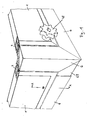
- FIG. 1 shows a corner of a cube or cuboid housing, which is constructed with wall elements according to the invention.
- the housing frame consists of housing frame profile rods 6, of which three housing frame profile rods cut together at a merge converge in each corner. These are held together by a corner piece 69, from which three outlets arranged at right angles to one another extend, onto which the housing frame profile rods 6 are pushed.
- the connection between the profile bar and corner piece can be made, for example, by gluing, screwing or riveting.
- Each housing frame profile rod is provided with two rear-engaging contact flanges 63 (see FIGS. 2 and 3) which form a circumferential contact flange in the assembled housing frame in each side opening of the housing, against which a wall element with a corresponding contact flange 22 abuts.
- a wall element is constructed from four profile bars 4, which are cut together to form a square or rectangular frame.
- the outer wall 15 and inner wall 18 (FIG. 4) of the profile rod have flat surfaces 7 and 8, respectively, on which the outer plate 2 and the inner plate 3, which consist for example of aluminum sheet, are glued on by means of a double-sided adhesive tape 9.
- the adhesive tape 9 is preferably made made of an elastic plastic material and has a certain thickness of, for example, 0.8 mm, so that thanks to the elastic deformability of this adhesive tape layer, thermal stresses between the different parts of the wall element can be compensated.
- connection between the four profile bars can only be established with this adhesive bandage.
- metallic angles can additionally be arranged in the interior of the connection points between adjacent profile bars.
- the space between the two plates 2 and 3 is filled with insulating material 5, for example mineral fiber wool.
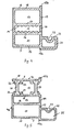
- Figure 4 shows an embodiment of a profile rod for a wall element in cross section.
- the hollow profile contains two partitions 16, 17, so that three chambers 11, 12, 13 are formed. One can see the two flat surfaces 7 and 8, to which the outer plate 2 and the inner plate 3 are glued.
- the profile bar wall 19, which forms the narrow outside of the wall element, is provided at both ends with a projection 19a, 19b, which form a stop edge for the plates 2 and 3 to be glued on and facilitate the adjustment of the plates during the gluing process.
- the contact flange 22 is formed by a profile part protruding at right angles from the profile rod wall 19, which in the exemplary embodiment shown is designed as a closed chamber 25, whereby on the one hand the contact flange 22 is mechanically stiffened and on the other hand a completely flat outer surface of the wall element is achieved. In principle, however, a simple wall protruding from the profile rod wall 19 is sufficient as the contact flange.
- the contact flange 22 has a groove 23 for receiving a Seal 24 provided. This seal is preferably designed as a highly effective rubber double lip seal that always reliably seals both under vacuum and over pressure in the interior of the housing.
- the locking mechanism 40 for fastening the wall element to the housing frame consists of a locking bolt 41 and a drive shaft 42 for rotating the locking bolt.
- the partitions 16 and 17 of the profile rod 4 are positioned so that the plate-shaped locking bar 41 is guided between the long side walls of the chamber 12 and is fixed by this in its position perpendicular to the plane of the wall element.
- the two long walls of the inner chamber 12 are provided with projecting webs 14, which are also milled to the exact dimension for the locking bolt when the slot 44 is milled.
- These webs also serve to firmly anchor the above-mentioned stiffening which may be used at the connection points of adjacent profile rods, the stiffening angles being inserted into the chambers 12 of the profile rods.
- the drive shaft 42 used for the locking bolt in the exemplary embodiment consists of a first cylindrical section 43a (FIGS. 6a and 6b), a driver profile part 43b and a second cylindrical section 43c.
- the driver profile part is designed as a square and fits into a corresponding square hole in the locking bolt 41.
- the drive shaft is mounted with its first cylindrical section 43a in corresponding holes in the outer wall 15 and the intermediate wall 16 and with the second cylindrical section 43b in the second intermediate wall 17th
- the locking mechanism 40 is mounted in such a way that a short slot 44 (FIG. 4) is milled into the profile rod wall 19, through which the locking bolt is inserted into the chamber 12 from the narrow side of the wall element.
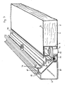
- the drive shaft is then pushed from the front of the wall element into the position shown in FIG. 3.
- the outer plate 2 prevents the drive shaft from falling out.
- the drive shaft is provided with a preferably square hole or through-channel 39, so that by inserting a square key from the outside through an opening in the outer plate 2 of the locking bolt can be rotated so that this through the slot 44 in the profile bar from this swings out and pushes behind the bearing flange 63 of the housing frame profile rod and presses the wall element with its seal firmly against the bearing flange 63 of the housing frame profile rod.
- the profile bars of the wall element can consist of poorly heat-conducting plastic, which is preferably glass fiber reinforced.
- FIG. 5 shows in cross section the possible formation of a profile rod in the event that this should consist of metal, but the thermal conductivity perpendicular to the plane of the wall element should be low.
- the profile rod in this case consists of two profile rod parts 4a and 4b, of which the first part forms the two chambers 11 and 12 for receiving the locking mechanisms.
- the second profile rod part is a substantially flat wall part 18, which is connected to the first part via two insulating web walls 20.
- the ends of the insulating webs are dovetail-shaped. Another way of training them is to wind them down at their ends keln, as shown in Figure 2 for the insulating web walls 65 of the housing frame profile rod.
- Correspondingly shaped projections 26, 27 for receiving the insulating web walls are provided on the sides of the two profile rod parts connected by the insulating web walls.
- the relatively narrow projection 26 is initially less angled in the extruded profile rod parts and is pressed after the insertion of the insulating web walls against the insulating web walls, whereby a rigid and firm connection is achieved.
- a permanently mounted actuating element 45 can also be provided instead of a square key, as shown in FIGS. 7a and 7b.
- This actuator consists of an axis 47, one end of which is designed as a slotted square 46, at the tip of which locking cams 46a are present. This square is inserted into the square hole 39 of the drive shaft 42 and locked with the locking cams 46a behind the inner end face of the drive shaft 42, so that the actuator can not be removed when the housing is closed.
- a star-shaped handle 48 for example, can be fixedly or rotatably placed on the part of the axis 47 protruding from the wall element.
- the part of the axis 47 protruding from the wall element is constructed from two cylindrical sections 47a, 47b with different diameters, so that the handle 48 is fixed in the axial direction by its appropriately designed bore section with the smaller diameter.
- An actuation of the locking bar 41 is only possible if the handle 48 is coupled with the axis 47 in the direction of rotation.
- a slot 49 is provided on the face of the upper cylindrical portion 47a, and two are axial in the upper part of the bore in the handle 48 fende diametrically opposite grooves 52 are present.
- the wall elements described above can be varied in many ways within the scope of the claims.
- the chamber 13 may be missing and the intermediate wall 17 may take over the function of the outer wall 18 directed towards the inside of the housing.
- the cylindrical portion 43c of the drive shaft 42 does not have to protrude from the intermediate wall 17.
- the second cylindrical section 43c of the drive shaft 42 of the locking mechanism 40 can also be omitted entirely.
- the thickness of a wall element can be 40 mm, for example, and the span can be up to 2 to 3 meters.
- the plates 2, 3 have a thickness of 1 mm, for example.
- the number of locking mechanisms provided per wall element depends on the size of the wall element and the requirements for the quality of the seal.
Landscapes
- Engineering & Computer Science (AREA)
- General Engineering & Computer Science (AREA)
- Mechanical Engineering (AREA)
- Refrigerator Housings (AREA)
- Building Environments (AREA)
- Audible-Bandwidth Dynamoelectric Transducers Other Than Pickups (AREA)
- Panels For Use In Building Construction (AREA)
- Pit Excavations, Shoring, Fill Or Stabilisation Of Slopes (AREA)
- Cartons (AREA)
- Piezo-Electric Or Mechanical Vibrators, Or Delay Or Filter Circuits (AREA)
- Finishing Walls (AREA)
Abstract
Wandelement (1) zum Einsetzen in die Seitenöffnungen eines aus Profilstangen (6) aufgebauten Gehäuserahmens, bei welchem die Seitenöffnungen von einem umlaufenden, hintergreifbaren Anlageflansch (63) für die Anlage des Wandelements (1) begrenzt sind, zu welchem Wandelement (1) eine Außenplatte (2) und einer Innenplatte (3) gehören, die auf Abstand voneinander gehalten sind, wobei der Raum zwischen den beiden Platten (2,3) mit Isoliermaterial (5) ausgefüllt ist, und welches Wandelement (1) an randnahen Stellen mit Verriegelungsmechanismen (40) versehen ist, mit denen das Wandelement (1) mit dem Gehäuserahmen verriegelbar ist. Gemäß der Erfindung besteht das Wandelement (1) längs seines Umfanges aus Profilstangen (4), die auf Gehrung aneinanderliegen und die an ihren zur Fläche des Wandelements (1) parallelen Seiten ebene Flächen aufweisen. Die Außenplatte (2) und die Innenplatte (3), die beide eben ausgebildet sind, sind an den genannten glatten Fläche der Profilstangen (4) befestigt und die Verriegelungsmechanismen (40) sind innerhalb der Profilstangen (4) angeordnet und mit einem aus den Schmalseiten des Wandelements (1) herausschwenkbaren Verschlußriegel (41) versehen. 
Description
Die Erfindung betrifft ein Wandelement zum Einsetzen in die Seitenöffnungen eines aus Profilstangen aufgebauten Gehäuserahmens. Eine solches Wandelement ist im wesentlichen bekannt aus dem DE-GM 7508449.The invention relates to a wall element for insertion into the side openings of a housing frame constructed from profile rods. Such a wall element is essentially known from DE-GM 7508449.
Bei dem bekannten Wandelement stehen die Verriegelungsmechanismen, mit denen das Wandelement mit dem Gehäuserahmen verbunden wird, aus der zum Gehäuseinneren gerichteten Seite des Wandelements hervor, was häufig nachteilig ist. Aus Gründen der Sauberhaltung und der Hygiene, insbesondere im medizinischen Bereich, besteht der Wunsch nach ebenen Innenwänden der aus den Wandelementen aufgebauten Gehäuse. Auch strömungstechnisch können sich die vorstehenden Verriegelungsmechanismen nachteilig auswirken, wenn die Gehäuse als Kanäle für ein strömendes Gas verwendet werden. Ein weiterer Nachteil des bekannten Wandelements besteht darin, daß die inneren und äußeren Wandplatten des Wandelementes an ihren Rändern abgewinkelt werden müssen, wodurch der Herstellungsaufwand groß ist.In the known wall element, the locking mechanisms with which the wall element is connected to the housing frame protrude from the side of the wall element facing the housing interior, which is often disadvantageous. For reasons of cleanliness and hygiene, especially in the medical field, there is a desire for flat inner walls of the housings constructed from the wall elements. From a fluidic point of view, the above locking mechanisms can also have a disadvantageous effect if the housings are used as channels for a flowing gas. Another disadvantage of the known wall element is that the inner and outer wall plates of the wall element have to be angled at their edges, as a result of which the production outlay is high.
Ferner ist es häufig wichtig, eine möglichst gute thermische und/oder akustische Isolierung der Innenräume der Gehäuse von der Umgebung zu erzielen. Bei den bekannten Wandelementen sind wärme- und schallübertragende Brücken vorhanden, die von den Verriegelungsmechanismen und häufig auch durch direkten Kontakt zwischen den Innen- und Außenblechen der Wandelemente gebildet werden.Furthermore, it is often important to achieve the best possible thermal and / or acoustic insulation of the interior of the housing from the environment. In the known wall elements, heat and sound-transmitting bridges are present, which are often caused by the locking mechanisms direct contact between the inner and outer sheets of the wall elements are formed.
Der Erfindung liegt die Aufgabe zugrunde, ein Wandelement der eingangs genannten Art zu entwickeln, welches auf der Gehäuseinnenseite durchgehend ebene Flächen aufweist und welches einfach herstellbar ist. Ferner soll das Wandelement so beschaffen sein, daß möglichst keine gut wärmeleitenden oder schalleitenden Verbindungen zwischen Außen- und Innenseite des Wandelements vorhanden sind.The invention has for its object to develop a wall element of the type mentioned, which has flat surfaces on the inside of the housing and which is easy to manufacture. Furthermore, the wall element should be such that, if possible, there are no good heat-conducting or sound-conducting connections between the outside and inside of the wall element.
Zur Lösung dieser Aufgabe wird ein Wandelement gemäß dem Oberbegriff des Anspruches 1 vorgeschlagen, welches erfindungsgemäß die im kennzeichnenden Teil des Anspruches 1 genannten Merkmale hat.To solve this problem, a wall element according to the preamble of
Vorteilhafte Ausgestaltungen der Erfindung sind in den weiteren Ansprüchen genannt.Advantageous embodiments of the invention are mentioned in the further claims.
Anhand der in den Figuren gezeigten Ausführungsbeispiele soll die Erfindung näher erläutert werden. Es zeigen
Figur 1 eine Eckausschnitt eines Gehäuses, welches mit Wandelementen gemäß der Erfindung aufgebaut ist, in perspektivischer Darstellung,Figur 2 eine Draufsicht auf den Ausschnitt gemäßFigur 1,Figur 3 in perspektivischer Darstellung einen Ausschnitt im Schnitt längs der Linie A-A inFigur 1 an einer Stelle, and er ein Verriegelungsmechanismus angeordnet ist,Figur 4 den Querschnitt eines ersten Ausführungsbeispiels einer Profilstange für ein Wandelement gemäß der Erfindung,Figur 5 den Querschnitt eines zweites Ausführungsbeispiels einer Profilstange für ein Wandelement gemäß der Erfindung,- Figur 6a und 6b ein Ausführungsbeispiel für die Antriebswelle eines Verriegelungsmechanismus, in Seitenansicht und Draufsicht,
- Figur 7a und 7b ein Ausführungsbeispiel für einen kuppelbaren Handgriff für einen Verriegelungsmechanismus in Seitenansicht und Draufsicht.
- 1 shows a perspective cutout of a corner section of a housing which is constructed with wall elements according to the invention,
- FIG. 2 shows a plan view of the detail according to FIG. 1,
- 3 shows a perspective illustration of a section in section along the line AA in FIG. 1 at a point at which a locking mechanism is arranged,
- FIG. 4 shows the cross section of a first exemplary embodiment of a profile rod for a wall element according to the invention,
- FIG. 5 shows the cross section of a second exemplary embodiment of a profile rod for a wall element according to the invention,
- 6a and 6b show an exemplary embodiment of the drive shaft of a locking mechanism, in side view and top view,
- Figure 7a and 7b an embodiment of a detachable handle for a locking mechanism in side view and top view.
Figur 1 zeigt eine Ecke eines würfel- oder quaderförmigen Gehäuses, welches mit Wandelementen gemäß der Erfindung aufgebaut ist. Der Gehäuserahmen besteht aus Gehäuserahmen-Profilstangen 6, von denen in jeder Ecke drei auf Gährung abgeschnittene Gehäuserahmen-Profilstangen zusammenlaufen. Diese werden zusammengehalten durch ein Eckstück 69, von welchem drei rechtwinklig zueinander angeordnete Stutzen ausgehen, auf welche die Gehäuserahmen-Profilstangen 6 aufgeschoben sind. Die Verbindung zwischen Profilstange und Eckstück kann beispielsweise durch Kleben, Schrauben oder Nieten erfolgen. Jede Gehäuserahmen-Profilstange ist mit zwei rechtwinklig zueinander angeordneten hintergreifbaren Anlageflanschen 63 (siehe Figuren 2 und 3) versehen, die im zusammengesteckten Gehäuserahmen in jeder Seitenöffnung des Gehäuses einen umlaufenden Anlageflansch bilden, gegen welchen ein Wandelement mit einem entsprechenden Anlageflansch 22 anliegt.Figure 1 shows a corner of a cube or cuboid housing, which is constructed with wall elements according to the invention. The housing frame consists of housing
Ein Wandelement ist aufgebaut aus vier Profilstangen 4, die auf Gährung geschnitten zu einem quadratischen oder rechteckförmigen Rahmen aneinandergelegt sind. Die Außenwand 15 und Innenwand 18 (Figur 4) der Profilstange weisen ebene Oberflächen 7 beziehungsweise 8 auf, auf denen die Außenplatte 2 und die Innenplatte 3, die beispielsweise aus Aluminiumblech bestehen, mittels eines doppelseitigen Klebebandes 9 aufgeklebt sind. Das Klebeband 9 besteht vorzugsweise aus einem elastischen Kunststoffmaterial und hat eine gewisse Dicke von beispielsweise 0,8 mm, so daß dank der elastischen Verformbarkeit dieser Klebebandschicht Wärmespannungen zwischen den verschiedenen Teilen des Wandelementes ausgeglichen werden können.A wall element is constructed from four
Die Verbindung zwischen den vier Profilstangen kann ausschließlich durch diesen Klebverband hergestellt sein. Bei großen und/oder stark belasteten Wandelementen können jedoch zusätzlich metallische Winkel an den Verbindungsstellen zwischen aneinander grenzenden Profilstangen im Inneren derselben angeordnet sein.The connection between the four profile bars can only be established with this adhesive bandage. In the case of large and / or heavily loaded wall elements, however, metallic angles can additionally be arranged in the interior of the connection points between adjacent profile bars.
Der Raum zwischen den beiden Platten 2 und 3 ist mit Isoliermaterial 5, beispielsweise Mineralfaserwolle, ausgefüllt.The space between the two
Figur 4 zeigt ein Ausführungsbeispiel einer Profilstange für ein Wandelement im Querschnitt. Das Hohlprofil enthält zwei Zwischenwände 16,17, so daß drei Kammern 11,12,13 gebildet werden. Man erkennt die beiden ebenen Flächen 7 beziehungsweise 8, an welchen die Außenplatte 2 beziehungsweise die Innenplatte 3 festgeklebt werden. Die Profilstangenwand 19, welche die schmale Außenseite des Wandelementes bildet, ist an ihren beiden Enden mit einem Vorsprung 19a,19b versehen, der eine Anschlagkante für die aufzuklebenden Platten 2 und 3 bilden und die Justierung der Platten beim Klebevorgang erleichtern. Der Anlageflansch 22 wird von einem rechtwinklig aus der Profilstangenwand 19 hervorstehenden, Profilteil gebildet, das im gezeigten Ausführungsbeispiel als geschlossene Kammer 25 ausgebildet ist, wodurch einerseits der Anlageflansch 22 mechanisch versteift wird und andererseits eine vollständig ebene Außenfläche des Wandelements erreicht wird. Im Prinzip genügt als Anlageflansch jedoch eine einfache aus der Profilstangenwand 19 hervortretende Wand. Der Anlageflansch 22 ist mit einer Nut 23 zur Aufnahme einer Dichtung 24 versehen. Diese Dichtung ist vorzugsweise als hochwirksame Gummidoppellippendichtung ausgebildet, die sowohl bei Unterdruck wie auch bei Überdruck im Inneren des Gehäuses stets zuverlässig dichtet.Figure 4 shows an embodiment of a profile rod for a wall element in cross section. The hollow profile contains two
Der Verriegelungsmechanismus 40 zur Befestigung des Wandelements am Gehäuserahmen besteht aus einem Verschlußriegel 41 und einer Antriebswelle 42 zur Drehung des Verschlußriegels. Die Zwischenwände 16 und 17 der Profilstange 4 sind so positioniert, daß der plattenförmige Verschlußriegel 41 zwischen den langen Seitenwänden der Kammer 12 geführt wird und von diesen in seiner Lage senkrecht zur Ebene des Wandelements festgelegt wird. Um gute Führungsflächen für den Verschlußriegel 41 zu erhalten, sind die beiden langen Wände der Innenkammer 12 mit vorstehenden Stegen 14 versehen, die beim Fräsen des Schlitzes 44 ebenfalls auf das exakte Maß für den Verschlußriegel abgefräst werden.The
Diese Stege dienen auch zur guten Verankerung der oben genannten eventuell verwendeten Versteifung an den Verbindungsstellen benachbarter Profilstangen, wobei die Versteifungswinkel in die Kammern 12 der Profilstangen eingesetzt werden.These webs also serve to firmly anchor the above-mentioned stiffening which may be used at the connection points of adjacent profile rods, the stiffening angles being inserted into the
Die im Ausführungsbeispiel verwendete Antriebswelle 42 für den Verschlußriegel besteht aus einem ersten zylindrischen Abschnitt 43a (Figur 6a und 6b), einem Mitnehmerprofilteil 43b und einem zweiten zylindrischen Abschnitt 43c. Das Mitnehmerprofilteil ist als Vierkant ausgebildet und paßt in ein entsprechendes Vierkantloch im Verschlußriegel 41. Die Antriebswelle ist mit ihrem ersten zylindrischen Abschnitt 43a in entsprechenden Löchern in der Außenwand 15 und der Zwischenwand 16 gelagert und mit dem zweiten zylindrischen Abschnitt 43b in der zweiten Zwischenwand 17.The
Die Montage des Verriegelungsmechanismus 40 erfolgt in der Weise, daß ein kurzer Schlitz 44 (Figur 4) in die Profilstangenwand 19 eingefräst wird, durch welchen der Verschlußriegel von der schmalen Seite des Wandelements aus in die Kammer 12 eingeschoben wird. Anschließend wird die Antriebswelle von der Vorderseite des Wandelements in die in Figur 3 gezeigte Position geschoben wird. Ein Herausfallen der Antriebswelle wird durch die Außenplatte 2 verhindert. Die Antriebswelle ist mit einem vorzugsweise als Vierkant ausgebildeten achsialen Loch oder durchgehenden Kanal 39 versehen, so daß durch Einstecken eines Vierkantschlüssels von außen durch eine Öffnung in der Außenplatte 2 der Verschlußriegel gedreht werden kann, so daß dieser durch den Schlitz 44 in der Profilstange aus dieser herausschwenkt und sich hinter den Anlageflansch 63 der Gehäuserahmen-Profilstange schiebt und das Wandelement mit seiner Dichtung fest gegen den Anlageflansch 63 der Gehäuserahmen-Profilstange andrückt.The
Zur Erzielung eines hohen Wärmedurchtrittswiderstandes senkrecht zur Ebene des Wandelementes können die Profilstangen des Wandelements aus schlecht wärmeleitendem Kunststoff, der vorzugsweise glasfaserverstärkt ist, bestehen.To achieve a high thermal resistance perpendicular to the plane of the wall element, the profile bars of the wall element can consist of poorly heat-conducting plastic, which is preferably glass fiber reinforced.
Figur 5 zeigt im Querschnitt die mögliche Ausbildung einer Profilstange für den Fall, daß diese aus Metall bestehen soll, die Wärmeleitfähigkeit senkrecht zur Ebene des Wandelements jedoch gering sein soll. Die Profilstange besteht in diesem Falle aus zwei Profilstangenteilen 4a und 4b, von denen das erste Teil die beiden Kammern 11 und 12 für die Aufnahme der Verriegelungsmechanismen bildet. Das zweite Profilstangenteil ist ein im wesentlichen ebenes Wandteil 18, welches mit dem ersten Teil über zwei Isolierstegwände 20 verbunden ist. Die Isolierstegwände sind an ihren Enden schwalbenschwanzförmig ausgebildet. Eine andere Möglichkeit ihrer Ausbildung besteht darin, sie an ihren Enden abzuwin keln, wie dies in Figur 2 für die Isolierstegwände 65 der Gehäuserahmen-Profilstange dargestellt ist.Figure 5 shows in cross section the possible formation of a profile rod in the event that this should consist of metal, but the thermal conductivity perpendicular to the plane of the wall element should be low. The profile rod in this case consists of two
An den durch die Isolierstegwände verbundenen Seiten der beiden Profilstangenteile sind entsprechend geformte Vorsprünge 26,27 zur Aufnahme der Isolierstegwände vorhanden. Der relativ schmale Vorsprung 26 ist bei den stranggepreßten Profilstangenteilen zunächst weniger stark abgewinkelt und wird nach dem Einsetzen der Isolierstegwände gegen die Isolierstegwände gedrückt, wodurch eine starre und feste Verbindung erreicht wird.Correspondingly shaped
Zur Betätigung der Verriegelungsmechanismen kann anstelle eines Vierkantschlüssels auch ein permanent montiertes Betätigungsglied 45 vorgesehen werden, wie es in den Figuren 7a und 7b dargestellt ist. Dieses Betätigungsglied besteht aus einer Achse 47, deren eines Ende als geschlitzter Vierkant 46 ausgebildet ist, an dessen Spitze Rastnocken 46a vorhanden sind. Dieser Vierkant wird in das Vierkantloch 39 der Antriebswelle 42 eingschoben und verrastet mit den Rastnocken 46a hinter der inneren Stirnseite der Antriebswelle 42, so daß das Betätigungsglied bei geschlossenem Gehäuse nicht wieder entfernt werden kann. Auf dem aus dem Wandelement herausragenden Teil der Achse 47 kann ein beispielsweise sternförmiger Handgriff 48 fest oder drehbar aufgesetzt sein. Im letztgenannten Falle ist der aus dem Wandelement herausragende Teil der Achse 47 aus zwei im Durchmesser unterschiedlichen zylindrischen Abschnitten 47a,47b aufgebaut, so daß der Handgriff 48 durch seinen entsprechend ausgebildeten Bohrungsabschnitt mit dem kleinerem Durchmesser in achsialer Richtung fixiert wird. Eine Betätigung des Verschlußriegels 41 ist nur möglich, wenn der Handgriff 48 mit der Achse 47 in Drehrichtung gekuppelt wird. Zu diesem Zweck ist an der Stirnseite des oberen zylindrischen Abschnittes 47a ein Schlitz 49 vorhanden, und in dem oberen Teil der Bohrung im Handgriff 48 sind zwei in Achsrichtung verlau fende diametral gegenüberliegende Nuten 52 vorhanden. Durch Einstecken eines entsprechend geformten Flachschlüssels 51 in den Schlitz 49 und die Nuten 52 werden Handgriff 48 und Achse 47 in Drehrichtung miteinander gekuppelt, so daß eine Betätigung des Verriegelungsmechanismus möglich ist.To actuate the locking mechanisms, a permanently mounted actuating element 45 can also be provided instead of a square key, as shown in FIGS. 7a and 7b. This actuator consists of an
Die vorbeschriebenen Wandelemente können im Rahmen der Ansprüche in vielfacher Weise variiert werden. So kann beispielsweise bei dem Profil gemäß Figur 4 die Kammer 13 fehlen und die Zwischenwand 17 die Funktion der zur Innenseite des Gehäuses gerichteten Außenwand 18 übernehmen. Ein Herausragen des zylindrischen Abschnitts 43c der Antriebswelle 42 aus der Zwischenwand 17 ist nicht erforderlich. Auch kann der zweite zylindrische Abschnitt 43c der Antriebswelle 42 des Verriegelungsmechanismus 40 ganz entfallen.The wall elements described above can be varied in many ways within the scope of the claims. For example, in the profile according to FIG. 4, the
Die Dicke eines Wandelementes kann beispielsweise 40 mm betragen, und die Spannweite bis zu 2 bis 3 Metern. Die Platten 2,3 haben beispielsweise eine Dicke von 1 mm.The thickness of a wall element can be 40 mm, for example, and the span can be up to 2 to 3 meters. The
Die Anzahl der pro Wandelement vorgesehenen Verriegelungsmechanismen hängt von der Größe des Wandelements und den Anforderungen an die Güte der Dichtung ab.The number of locking mechanisms provided per wall element depends on the size of the wall element and the requirements for the quality of the seal.
Claims (18)
Priority Applications (1)
| Application Number | Priority Date | Filing Date | Title |
|---|---|---|---|
| AT88103468T ATE92287T1 (en) | 1987-03-12 | 1988-03-05 | WALL ELEMENT FOR INSERTING INTO THE SIDE OPENINGS OF A HOUSING FRAME CONSTRUCTED FROM PROFILE RODS. |
Applications Claiming Priority (2)
| Application Number | Priority Date | Filing Date | Title |
|---|---|---|---|
| DE19873707916 DE3707916A1 (en) | 1987-03-12 | 1987-03-12 | WALL ELEMENT FOR INSERTION IN THE SIDE OPENINGS OF A HOUSING FRAME CONSTRUCTED FROM PROFILE RODS |
| DE3707916 | 1987-03-12 |
Publications (3)
| Publication Number | Publication Date |
|---|---|
| EP0281982A2 true EP0281982A2 (en) | 1988-09-14 |
| EP0281982A3 EP0281982A3 (en) | 1989-05-10 |
| EP0281982B1 EP0281982B1 (en) | 1993-08-04 |
Family
ID=6322834
Family Applications (1)
| Application Number | Title | Priority Date | Filing Date |
|---|---|---|---|
| EP88103468A Expired - Lifetime EP0281982B1 (en) | 1987-03-12 | 1988-03-05 | Wall element to be mounted in the side openings of a housing frame made from profiles |
Country Status (4)
| Country | Link |
|---|---|
| EP (1) | EP0281982B1 (en) |
| AT (1) | ATE92287T1 (en) |
| AU (1) | AU613019B2 (en) |
| DE (2) | DE3707916A1 (en) |
Families Citing this family (2)
| Publication number | Priority date | Publication date | Assignee | Title |
|---|---|---|---|---|
| DE3939421C1 (en) * | 1989-11-29 | 1990-10-25 | Eldon N.V., Drachten, Nl | |
| DE29618701U1 (en) * | 1996-10-26 | 1998-02-26 | ELEK GmbH, 41470 Neuss | Frame for a control cabinet |
Family Cites Families (8)
| Publication number | Priority date | Publication date | Assignee | Title |
|---|---|---|---|---|
| DE7508449U (en) * | 1975-07-17 | Fischbach R Kg | Wall element for insertion into the frame of a device housing | |
| US3327447A (en) * | 1965-04-22 | 1967-06-27 | Traulsen & Co Inc | Interlocking joint for abutted edges of insulated panel sections |
| US3392497A (en) * | 1966-10-21 | 1968-07-16 | Delron Company Inc | Modular enclosure with clamp joined panels |
| DE2731328A1 (en) * | 1977-07-12 | 1979-02-01 | Guenter Smitka | Housing for electrical and electronic equipment - has frame elements with fastening members for direct attachment of mounting bars |
| SE411928B (en) * | 1978-07-11 | 1980-02-11 | Wemas Modulbyggen Ab | DEVICE FOR OUTDOORS AND LIKE COLD AND HOT SEPARATE DOORS |
| AU7287081A (en) * | 1980-07-18 | 1982-01-21 | Clearlight Pty. Ltd. | Connecting means |
| DE3120076A1 (en) * | 1981-05-20 | 1982-12-09 | Helmar Dr.Dr. 8530 Neustadt Nahr | Heat-insulating profile body |
| IT8421341V0 (en) * | 1984-03-23 | 1984-03-23 | Semilavorati Spa | ANTI-CONDENSATION METAL PROFILE PARTICULARLY FOR REFRIGERATING, CONDITIONING, EXPOSURE AND SIMILAR ROOMS. |
-
1987
- 1987-03-12 DE DE19873707916 patent/DE3707916A1/en not_active Withdrawn
-
1988
- 1988-03-05 EP EP88103468A patent/EP0281982B1/en not_active Expired - Lifetime
- 1988-03-05 AT AT88103468T patent/ATE92287T1/en active
- 1988-03-05 DE DE8888103468T patent/DE3882749D1/en not_active Expired - Fee Related
- 1988-03-11 AU AU13007/88A patent/AU613019B2/en not_active Ceased
Also Published As
| Publication number | Publication date |
|---|---|
| DE3707916A1 (en) | 1988-09-22 |
| EP0281982B1 (en) | 1993-08-04 |
| ATE92287T1 (en) | 1993-08-15 |
| EP0281982A3 (en) | 1989-05-10 |
| AU613019B2 (en) | 1991-07-25 |
| DE3882749D1 (en) | 1993-09-09 |
| AU1300788A (en) | 1988-09-15 |
Similar Documents
| Publication | Publication Date | Title |
|---|---|---|
| DE3711222C2 (en) | ||
| DE2152341C3 (en) | Construction toys | |
| CH652433A5 (en) | METHOD AND DEVICE FOR CONNECTING PANEL ELEMENTS. | |
| DE2634774C2 (en) | Wall or ceiling cladding made from slats | |
| EP0281983B1 (en) | Assembling system for a housing frame | |
| DE2745846A1 (en) | Assembled composite heat insulating frame or partition element - has metal units notched ribs engaged by plastic U=piece flange end notches (NL 8.4.78) | |
| EP0001836A1 (en) | Structural assembly of individual wall units | |
| DE2229893A1 (en) | Grate for ventilation openings | |
| DE102013016518A1 (en) | Three-dimensional structure | |
| DE8030908U1 (en) | DEVICE FOR CONNECTING PANELS AND / OR RODS | |
| DE2811142B2 (en) | Door leaf in hollow construction | |
| EP0033490A1 (en) | Construction set for making carcass frames | |
| DE102004016212B4 (en) | Corner connection for a window, door or facade frame | |
| EP0281982B1 (en) | Wall element to be mounted in the side openings of a housing frame made from profiles | |
| CH620282A5 (en) | ||
| EP0030385A1 (en) | Construction element for doors, gates or the like and process for its production | |
| DE2203237A1 (en) | COMPOSITE THERMAL INSULATING PROFILE FOR WINDOW FRAMES, DOOR FRAMES OR THE LIKE | |
| DE2208289C2 (en) | Ventilation device | |
| DE2308342A1 (en) | PANEL-LIKE COMPONENT | |
| DE2755135C2 (en) | ||
| CH624449A5 (en) | Device for connecting a covering frame to a base frame for windows, facades or room partitions | |
| DE68910324T2 (en) | SHEET FILM CASSETTE. | |
| EP0984119B1 (en) | Spring spindle, in particular a square-spindle for a handle | |
| DE202019103487U1 (en) | Spreadable corner bracket | |
| DE2552983A1 (en) | Fixing device for air conditioning cabinets etc. - has internal dowels secured by tapered transverse bolts |
Legal Events
| Date | Code | Title | Description |
|---|---|---|---|
| PUAI | Public reference made under article 153(3) epc to a published international application that has entered the european phase |
Free format text: ORIGINAL CODE: 0009012 |
|
| AK | Designated contracting states |
Kind code of ref document: A2 Designated state(s): AT BE CH DE FR GB IT LI NL SE |
|
| PUAL | Search report despatched |
Free format text: ORIGINAL CODE: 0009013 |
|
| RHK1 | Main classification (correction) |
Ipc: A47B 47/03 |
|
| AK | Designated contracting states |
Kind code of ref document: A3 Designated state(s): AT BE CH DE FR GB IT LI NL SE |
|
| 17P | Request for examination filed |
Effective date: 19891030 |
|
| 17Q | First examination report despatched |
Effective date: 19910926 |
|
| GRAA | (expected) grant |
Free format text: ORIGINAL CODE: 0009210 |
|
| AK | Designated contracting states |
Kind code of ref document: B1 Designated state(s): AT BE CH DE FR GB IT LI NL SE |
|
| REF | Corresponds to: |
Ref document number: 92287 Country of ref document: AT Date of ref document: 19930815 Kind code of ref document: T |
|
| REF | Corresponds to: |
Ref document number: 3882749 Country of ref document: DE Date of ref document: 19930909 |
|
| ET | Fr: translation filed | ||
| ITF | It: translation for a ep patent filed | ||
| GBT | Gb: translation of ep patent filed (gb section 77(6)(a)/1977) |
Effective date: 19931027 |
|
| PGFP | Annual fee paid to national office [announced via postgrant information from national office to epo] |
Ref country code: GB Payment date: 19940303 Year of fee payment: 7 |
|
| PGFP | Annual fee paid to national office [announced via postgrant information from national office to epo] |
Ref country code: FR Payment date: 19940310 Year of fee payment: 7 |
|
| PGFP | Annual fee paid to national office [announced via postgrant information from national office to epo] |
Ref country code: BE Payment date: 19940315 Year of fee payment: 7 |
|
| PGFP | Annual fee paid to national office [announced via postgrant information from national office to epo] |
Ref country code: SE Payment date: 19940324 Year of fee payment: 7 |
|
| PGFP | Annual fee paid to national office [announced via postgrant information from national office to epo] |
Ref country code: CH Payment date: 19940328 Year of fee payment: 7 |
|
| PGFP | Annual fee paid to national office [announced via postgrant information from national office to epo] |
Ref country code: AT Payment date: 19940329 Year of fee payment: 7 |
|
| PGFP | Annual fee paid to national office [announced via postgrant information from national office to epo] |
Ref country code: NL Payment date: 19940331 Year of fee payment: 7 |
|
| PLBE | No opposition filed within time limit |
Free format text: ORIGINAL CODE: 0009261 |
|
| STAA | Information on the status of an ep patent application or granted ep patent |
Free format text: STATUS: NO OPPOSITION FILED WITHIN TIME LIMIT |
|
| 26N | No opposition filed | ||
| EAL | Se: european patent in force in sweden |
Ref document number: 88103468.0 |
|
| PG25 | Lapsed in a contracting state [announced via postgrant information from national office to epo] |
Ref country code: GB Effective date: 19950305 Ref country code: AT Effective date: 19950305 |
|
| PG25 | Lapsed in a contracting state [announced via postgrant information from national office to epo] |
Ref country code: SE Effective date: 19950306 |
|
| PG25 | Lapsed in a contracting state [announced via postgrant information from national office to epo] |
Ref country code: LI Effective date: 19950331 Ref country code: CH Effective date: 19950331 Ref country code: BE Effective date: 19950331 |
|
| BERE | Be: lapsed |
Owner name: FISCHBACH G.M.B.H. & CO. K.G. VERWALTUNGSGESELLSC Effective date: 19950331 |
|
| PG25 | Lapsed in a contracting state [announced via postgrant information from national office to epo] |
Ref country code: NL Effective date: 19951001 |
|
| GBPC | Gb: european patent ceased through non-payment of renewal fee |
Effective date: 19950305 |
|
| PG25 | Lapsed in a contracting state [announced via postgrant information from national office to epo] |
Ref country code: FR Free format text: LAPSE BECAUSE OF NON-PAYMENT OF DUE FEES Effective date: 19951130 |
|
| REG | Reference to a national code |
Ref country code: CH Ref legal event code: PL |
|
| NLV4 | Nl: lapsed or anulled due to non-payment of the annual fee |
Effective date: 19951001 |
|
| EUG | Se: european patent has lapsed |
Ref document number: 88103468.0 |
|
| REG | Reference to a national code |
Ref country code: FR Ref legal event code: ST |
|
| PGFP | Annual fee paid to national office [announced via postgrant information from national office to epo] |
Ref country code: DE Payment date: 19960529 Year of fee payment: 9 |
|
| PG25 | Lapsed in a contracting state [announced via postgrant information from national office to epo] |
Ref country code: DE Effective date: 19971202 |
|
| PG25 | Lapsed in a contracting state [announced via postgrant information from national office to epo] |
Ref country code: IT Free format text: LAPSE BECAUSE OF NON-PAYMENT OF DUE FEES;WARNING: LAPSES OF ITALIAN PATENTS WITH EFFECTIVE DATE BEFORE 2007 MAY HAVE OCCURRED AT ANY TIME BEFORE 2007. THE CORRECT EFFECTIVE DATE MAY BE DIFFERENT FROM THE ONE RECORDED. Effective date: 20050305 |