EP0281983A2 - Système d'assemblage pour un bâti d'enceinte - Google Patents
Système d'assemblage pour un bâti d'enceinte Download PDFInfo
- Publication number
- EP0281983A2 EP0281983A2 EP88103469A EP88103469A EP0281983A2 EP 0281983 A2 EP0281983 A2 EP 0281983A2 EP 88103469 A EP88103469 A EP 88103469A EP 88103469 A EP88103469 A EP 88103469A EP 0281983 A2 EP0281983 A2 EP 0281983A2
- Authority
- EP
- European Patent Office
- Prior art keywords
- profile
- plug
- wall
- profile rod
- walls
- Prior art date
- Legal status (The legal status is an assumption and is not a legal conclusion. Google has not performed a legal analysis and makes no representation as to the accuracy of the status listed.)
- Granted
Links
Images

Classifications
-
- H—ELECTRICITY
- H02—GENERATION; CONVERSION OR DISTRIBUTION OF ELECTRIC POWER
- H02B—BOARDS, SUBSTATIONS OR SWITCHING ARRANGEMENTS FOR THE SUPPLY OR DISTRIBUTION OF ELECTRIC POWER
- H02B1/00—Frameworks, boards, panels, desks, casings; Details of substations or switching arrangements
- H02B1/01—Frameworks
- H02B1/013—Profiles for cabinet frames
-
- H—ELECTRICITY
- H02—GENERATION; CONVERSION OR DISTRIBUTION OF ELECTRIC POWER
- H02B—BOARDS, SUBSTATIONS OR SWITCHING ARRANGEMENTS FOR THE SUPPLY OR DISTRIBUTION OF ELECTRIC POWER
- H02B1/00—Frameworks, boards, panels, desks, casings; Details of substations or switching arrangements
- H02B1/01—Frameworks
- H02B1/014—Corner connections for frameworks
Definitions
- the invention relates to a plug system for constructing a housing frame according to the preamble of claim 1.
- a 16 such plug system is essentially known from DE-OS 2511584.
- the profile rods are designed as one-piece metallic extruded profiles, the center line a (FIG. 3) of the sliding grooves lying in the profile rod cross section extending approximately at 45 degrees to the long side walls of the profile rod.
- a disadvantage of the known plug-in system is that the profile rods form undesirable thermal bridges between the interior of the housing and the environment when using heat-insulating wall elements.
- Another disadvantage is the arrangement of the sliding groove which runs obliquely to the side walls of the profile rod and which often makes it more difficult to fix internals.
- the invention has for its object to develop a plug-in system of the type mentioned, in which the passage of heat through the profile bars is significantly more difficult and the fastening of built-in parts is facilitated by means of screws in the sliding grooves.
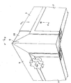
- Figure 1 shows a corner of a cube or cuboid housing, which is constructed with the aid of a plug-in system according to the invention.
- the housing frame consists of profiled bars 6, of which three profiled bars cut to size converge in each corner. These are held together by a corner piece 69, which consists of a central cube-shaped part, from which three outlets arranged at right angles to one another extend, onto which the profile rods 6 are pushed.
- the corner piece 69 is visible by breaking off the end of a profile bar made.
- the connection between the profile stems and the corner pieces can be made, for example, by gluing, screwing or riveting.
- the profile bars are pushed so far over the corner piece 69 that this disappears completely in the profile bars.
- wall elements 1 are inserted, which bear with a contact flange 22 against a contact flange 63 of the profile rods 6 and can be locked by means of a locking bolt 41 on the wall element which engages behind the contact flange 63.
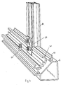
- the profile rod 6 shown in cross section in FIG. 3 consists of a first metallic profile rod part 60 and a second metallic profile rod part 70.
- the first profile rod part 60 forms a closed chamber 66 in cross section, which is delimited by two long side walls 61 adjoining one another at right angles, the other of which Each ends a short side wall 62 adjoins at right angles, the ends of which are connected to one another by a side wall 65 running obliquely to the other side walls 61, 62.
- the latter side wall 65 can also be dispensed with. From the connection points between the side walls 62 and 65, a contact flange 63 for the contact of the wall elements extends parallel to a long side wall 61.
- the second profile rod part 70 consists essentially of two known ones arranged at right angles to one another and parallel to one housing side wall Sliding grooves 71 for receiving screws 91, with the help of which devices can be fastened inside the housing.
- the screws are preferably designed as hammer head screws, which can be inserted at any point by turning into the sliding groove.
- the two profile rod parts 60 and 70 are connected to one another via two insulating web walls 65, which extend from the rear of the contact flanges 63 to the lower side of the base wall 72 of the sliding grooves extend.
- the ends of the insulating webs are dovetail-shaped.
- the relatively narrow projection 26 is initially less angled in the extruded profile rod parts and is pressed after the insertion of the insulating web walls against the insulating web walls, whereby a rigid and firm connection is achieved.
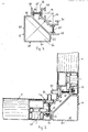
- FIG. 4 shows the connection of such an intermediate profile rod 80 to an outer profile rod 6.
- the cross-sectional profile of this intermediate profile rod can be seen in FIG. 5. It consists of two metallic intermediate profiles 81, 82, both of which are essentially plate-shaped and are connected to one another via two heat-insulating insulating web walls 65.
- the first intermediate profile rod part 81 lying on the outside of the housing forms a double contact flange 83 for two adjacent wall elements 1, of which the left one lies against the flange in FIG can be inserted from the outside, can be rotated.
- the second intermediate profile rod part 82 has a sliding groove 71 on its inward side.
- projections 26, 27 are again present for receiving the correspondingly shaped ends of the insulating web walls.
- the outermost flanges 86 of the displacement groove 71 are in the direction of Side of the intermediate profile rod extended so far that they adjoin a connected wall element.
- the intermediate profile rod is butted onto the high edges of the contact flange 63 and the displacement groove 71 and is connected to the latter with a bracket 90 and two screws via adjacent displacement grooves of the intermediate profile rod and the main profile rod.
Landscapes
- Engineering & Computer Science (AREA)
- Power Engineering (AREA)
- Connector Housings Or Holding Contact Members (AREA)
- Body Structure For Vehicles (AREA)
- Building Environments (AREA)
- Mutual Connection Of Rods And Tubes (AREA)
- Patch Boards (AREA)
Priority Applications (1)
| Application Number | Priority Date | Filing Date | Title |
|---|---|---|---|
| AT88103469T ATE91858T1 (de) | 1987-03-12 | 1988-03-05 | Stecksystem zum aufbau eines gehaeuserahmens. |
Applications Claiming Priority (2)
| Application Number | Priority Date | Filing Date | Title |
|---|---|---|---|
| DE8703695U | 1987-03-12 | ||
| DE8703695U DE8703695U1 (de) | 1987-03-12 | 1987-03-12 | Bauelementensatz für einen Gehäuserahmen |
Publications (3)
| Publication Number | Publication Date |
|---|---|
| EP0281983A2 true EP0281983A2 (fr) | 1988-09-14 |
| EP0281983A3 EP0281983A3 (en) | 1989-05-03 |
| EP0281983B1 EP0281983B1 (fr) | 1993-07-28 |
Family
ID=6805739
Family Applications (1)
| Application Number | Title | Priority Date | Filing Date |
|---|---|---|---|
| EP88103469A Expired - Lifetime EP0281983B1 (fr) | 1987-03-12 | 1988-03-05 | Système d'assemblage pour un bâti d'enceinte |
Country Status (3)
| Country | Link |
|---|---|
| EP (1) | EP0281983B1 (fr) |
| AT (1) | ATE91858T1 (fr) |
| DE (2) | DE8703695U1 (fr) |
Cited By (7)
| Publication number | Priority date | Publication date | Assignee | Title |
|---|---|---|---|---|
| FR2648005A1 (fr) * | 1989-06-05 | 1990-12-07 | Merlin Gerin | Armoire etanche d'appareillage electrique |
| FR2675961A1 (fr) * | 1991-04-29 | 1992-10-30 | Merlin Gerin | Rehausse pour coffret electrique. |
| FR2682257A1 (fr) * | 1991-10-02 | 1993-04-09 | Loh Rittal Werk Gmbh Co | Profile creux pour un chassis-cadre d'une armoire de commutation. |
| WO1995011538A1 (fr) * | 1993-10-23 | 1995-04-27 | Rittal-Werk Rudolf Loh Gmbh & Co. Kg | Armoire de distribution a bati constitue de montants |
| WO2001040599A1 (fr) * | 1999-11-30 | 2001-06-07 | Ul Tech Ag | Systeme de construction en bâti |
| GB2529827A (en) * | 2014-09-02 | 2016-03-09 | Cp Cases Ltd | Electronic rack and mounting chassis |
| CN108899779A (zh) * | 2018-08-27 | 2018-11-27 | 江苏南瑞帕威尔电气有限公司 | 一种加强型开关柜后门及加强型开关柜 |
Families Citing this family (13)
| Publication number | Priority date | Publication date | Assignee | Title |
|---|---|---|---|---|
| DE9203100U1 (de) * | 1992-03-09 | 1993-07-08 | Böwe Systec AG, 8900 Augsburg | Grundgestell für Maschinen u.dgl. |
| DE4227532C3 (de) * | 1992-08-20 | 1999-01-14 | Thielmann Ag Kg | Rahmenprofil für das Rahmengestell eines Schaltschrankes |
| DE9217801U1 (de) * | 1992-12-23 | 1993-02-25 | Hansa Ventilatoren u. Maschinenbau Neumann GmbH & Co KG, 2915 Saterland | Profil zur Aufnahme von Beplankungselementen |
| DE4336187C2 (de) * | 1993-10-23 | 1996-12-12 | Loh Kg Rittal Werk | Rahmenschenkel für ein Rahmengestell eines Schaltschrankes |
| DE4336204C2 (de) * | 1993-10-23 | 1996-11-07 | Loh Kg Rittal Werk | Rahmengestell für einen Schaltschrank |
| DE4439551C1 (de) * | 1994-11-05 | 1995-12-21 | Loh Kg Rittal Werk | Rahmenschenkel für ein Rahmengestell eines Schaltschrankes |
| DE19507438C1 (de) * | 1995-03-03 | 1996-04-04 | Loh Kg Rittal Werk | Vorrichtung zum Verbinden einer Montageschiene mit einem Rahmenschenkel eines Rahmengestelles eines Schaltschrankes |
| DE19536926C2 (de) * | 1995-10-04 | 1999-02-04 | Loh Kg Rittal Werk | Rahmenschenkel für einen Schaltschrank |
| DE19536950C1 (de) * | 1995-10-04 | 1996-11-21 | Loh Kg Rittal Werk | Rahmenschenkel für ein Rahmengestell eines Schaltschrankes |
| DE19537016C1 (de) * | 1995-10-04 | 1996-10-10 | Loh Kg Rittal Werk | Rahmengestell für einen Schaltschrank |
| DE19544432C2 (de) * | 1995-11-29 | 1999-07-29 | Loh Kg Rittal Werk | Rahmengestell für einen Schaltschrank |
| DE202018100613U1 (de) * | 2018-02-05 | 2018-02-14 | Rittal Gmbh & Co. Kg | Anordnung mit zwei über einen Anreihverbinder miteinander verbundenen Schaltschrankrahmengestellen |
| BE1032554B1 (nl) * | 2024-04-19 | 2025-11-17 | Rudi Dries | Modulair systeem voor bewaren en etaleren van flessen, en kastsysteem |
Family Cites Families (4)
| Publication number | Priority date | Publication date | Assignee | Title |
|---|---|---|---|---|
| DE2731328A1 (de) * | 1977-07-12 | 1979-02-01 | Guenter Smitka | Gehaeuse zur aufnahme von insbesondere elektrischen und elektronischen geraeten, computerschraenken sowie von kraft- und arbeitsmaschinen |
| DE3033206C2 (de) * | 1980-09-03 | 1984-07-05 | Josef Gartner & Co, 8883 Gundelfingen | Verbundprofil |
| DE3120076A1 (de) * | 1981-05-20 | 1982-12-09 | Helmar Dr.Dr. 8530 Neustadt Nahr | Waermeisolierender profilkoerper |
| IT8421341V0 (it) * | 1984-03-23 | 1984-03-23 | Semilavorati Spa | Profilato metallico anticondensa particolarmente per camere frigorifere, di condizionamenti, di esposizione e simili. |
-
1987
- 1987-03-12 DE DE8703695U patent/DE8703695U1/de not_active Expired
-
1988
- 1988-03-05 EP EP88103469A patent/EP0281983B1/fr not_active Expired - Lifetime
- 1988-03-05 AT AT88103469T patent/ATE91858T1/de not_active IP Right Cessation
- 1988-03-05 DE DE8888103469T patent/DE3882555D1/de not_active Expired - Fee Related
Cited By (14)
| Publication number | Priority date | Publication date | Assignee | Title |
|---|---|---|---|---|
| US5202818A (en) * | 1989-06-05 | 1993-04-13 | Merlin Gerin | Sealed switchgear cabinet |
| EP0402276A1 (fr) * | 1989-06-05 | 1990-12-12 | Merlin Gerin | Armoire étanche d'appareillage électrique |
| TR24645A (tr) * | 1989-06-05 | 1992-01-01 | Merlin Gerin | Sizdirmaz kilinmis tevzi panosu. |
| AU624717B2 (en) * | 1989-06-05 | 1992-06-18 | Schneider Electric Sa | Sealed switchgear cabinet |
| FR2648005A1 (fr) * | 1989-06-05 | 1990-12-07 | Merlin Gerin | Armoire etanche d'appareillage electrique |
| FR2675961A1 (fr) * | 1991-04-29 | 1992-10-30 | Merlin Gerin | Rehausse pour coffret electrique. |
| EP0512929A1 (fr) * | 1991-04-29 | 1992-11-11 | Schneider Electric Sa | Rehaussé pour coffret électrique |
| FR2682257A1 (fr) * | 1991-10-02 | 1993-04-09 | Loh Rittal Werk Gmbh Co | Profile creux pour un chassis-cadre d'une armoire de commutation. |
| WO1995011538A1 (fr) * | 1993-10-23 | 1995-04-27 | Rittal-Werk Rudolf Loh Gmbh & Co. Kg | Armoire de distribution a bati constitue de montants |
| WO2001040599A1 (fr) * | 1999-11-30 | 2001-06-07 | Ul Tech Ag | Systeme de construction en bâti |
| GB2529827A (en) * | 2014-09-02 | 2016-03-09 | Cp Cases Ltd | Electronic rack and mounting chassis |
| GB2529827B (en) * | 2014-09-02 | 2017-01-04 | Cp Cases Ltd | Electronic rack and mounting chassis |
| US10045460B2 (en) | 2014-09-02 | 2018-08-07 | Cp Cases Limited | Electronic rack and mounting chassis |
| CN108899779A (zh) * | 2018-08-27 | 2018-11-27 | 江苏南瑞帕威尔电气有限公司 | 一种加强型开关柜后门及加强型开关柜 |
Also Published As
| Publication number | Publication date |
|---|---|
| DE3882555D1 (de) | 1993-09-02 |
| EP0281983A3 (en) | 1989-05-03 |
| DE8703695U1 (de) | 1987-12-17 |
| EP0281983B1 (fr) | 1993-07-28 |
| ATE91858T1 (de) | 1993-08-15 |
Similar Documents
| Publication | Publication Date | Title |
|---|---|---|
| EP0281983A2 (fr) | Système d'assemblage pour un bâti d'enceinte | |
| EP0404284B1 (fr) | Charpente pour une cabine de distribution à éléments profilés coudés plusieurs fois | |
| EP0278252A2 (fr) | Profilé d'ancrage | |
| DE2152341B2 (de) | Bauspielzeug | |
| EP0061994A2 (fr) | Elément d'assemblage en forme de coin pour l'assemblage rapide et solide de profils | |
| DE29520491U1 (de) | Kastenschleifleitung | |
| DE9412465U1 (de) | Modulares Steckverbindungssystem | |
| EP0032408A2 (fr) | Profilé composite thermiquement isolant | |
| DE8710777U1 (de) | Faltbarer Kabelkanal | |
| DE19824063A1 (de) | I-förmiger Träger für Gebäudekonstruktionen | |
| EP0039467A2 (fr) | Pièce d'écartement | |
| EP0067970A1 (fr) | Dispositif de fixation pour éléments de façade | |
| EP0623530A1 (fr) | Système de convoyeur aérien avec un set de profilés de montage | |
| EP0182288A2 (fr) | Construction parallélépipédique | |
| DE3001445A1 (de) | Mit brettern aufgebauter hohlbalken | |
| DE3706236C2 (de) | Verbindungselement für zwei Tragteile | |
| DE9116531U1 (de) | Systembaukasten | |
| DE841499C (de) | Bauteil in Form einer U-Schiene | |
| EP0959536A1 (fr) | Bloc multiprises | |
| DE3610377C2 (fr) | ||
| DE4227531C2 (de) | Eckverbinder für ein Rahmengestell eines Schaltschrankes | |
| DE20119280U1 (de) | Brettstapelelement mit zug- und druckfesten Verbindungselementen | |
| DE10114450A1 (de) | Bausatz für ein Haus, insbesondere ein Gartenhaus | |
| DE2622186A1 (de) | Betonplatte | |
| DE2511584C3 (de) | Stecksystem zum Aufbau von Gehäuserahmen |
Legal Events
| Date | Code | Title | Description |
|---|---|---|---|
| PUAI | Public reference made under article 153(3) epc to a published international application that has entered the european phase |
Free format text: ORIGINAL CODE: 0009012 |
|
| AK | Designated contracting states |
Kind code of ref document: A2 Designated state(s): AT BE CH DE FR GB IT LI NL SE |
|
| PUAL | Search report despatched |
Free format text: ORIGINAL CODE: 0009013 |
|
| RHK1 | Main classification (correction) |
Ipc: A47B 47/03 |
|
| AK | Designated contracting states |
Kind code of ref document: A3 Designated state(s): AT BE CH DE FR GB IT LI NL SE |
|
| 17P | Request for examination filed |
Effective date: 19891021 |
|
| 17Q | First examination report despatched |
Effective date: 19910926 |
|
| GRAA | (expected) grant |
Free format text: ORIGINAL CODE: 0009210 |
|
| AK | Designated contracting states |
Kind code of ref document: B1 Designated state(s): AT BE CH DE FR GB IT LI NL SE |
|
| REF | Corresponds to: |
Ref document number: 91858 Country of ref document: AT Date of ref document: 19930815 Kind code of ref document: T |
|
| REF | Corresponds to: |
Ref document number: 3882555 Country of ref document: DE Date of ref document: 19930902 |
|
| ET | Fr: translation filed | ||
| ITF | It: translation for a ep patent filed | ||
| GBT | Gb: translation of ep patent filed (gb section 77(6)(a)/1977) |
Effective date: 19931027 |
|
| PGFP | Annual fee paid to national office [announced via postgrant information from national office to epo] |
Ref country code: GB Payment date: 19940303 Year of fee payment: 7 |
|
| PGFP | Annual fee paid to national office [announced via postgrant information from national office to epo] |
Ref country code: FR Payment date: 19940310 Year of fee payment: 7 |
|
| PGFP | Annual fee paid to national office [announced via postgrant information from national office to epo] |
Ref country code: BE Payment date: 19940315 Year of fee payment: 7 |
|
| PGFP | Annual fee paid to national office [announced via postgrant information from national office to epo] |
Ref country code: SE Payment date: 19940324 Year of fee payment: 7 |
|
| PGFP | Annual fee paid to national office [announced via postgrant information from national office to epo] |
Ref country code: CH Payment date: 19940328 Year of fee payment: 7 |
|
| PGFP | Annual fee paid to national office [announced via postgrant information from national office to epo] |
Ref country code: AT Payment date: 19940329 Year of fee payment: 7 |
|
| PGFP | Annual fee paid to national office [announced via postgrant information from national office to epo] |
Ref country code: NL Payment date: 19940331 Year of fee payment: 7 |
|
| PLBE | No opposition filed within time limit |
Free format text: ORIGINAL CODE: 0009261 |
|
| STAA | Information on the status of an ep patent application or granted ep patent |
Free format text: STATUS: NO OPPOSITION FILED WITHIN TIME LIMIT |
|
| 26N | No opposition filed | ||
| EAL | Se: european patent in force in sweden |
Ref document number: 88103469.8 |
|
| PG25 | Lapsed in a contracting state [announced via postgrant information from national office to epo] |
Ref country code: GB Effective date: 19950305 Ref country code: AT Effective date: 19950305 |
|
| PG25 | Lapsed in a contracting state [announced via postgrant information from national office to epo] |
Ref country code: SE Effective date: 19950306 |
|
| PG25 | Lapsed in a contracting state [announced via postgrant information from national office to epo] |
Ref country code: LI Effective date: 19950331 Ref country code: CH Effective date: 19950331 Ref country code: BE Effective date: 19950331 |
|
| BERE | Be: lapsed |
Owner name: FISCHBACH G.M.B.H. & CO. K.G. Effective date: 19950331 |
|
| PG25 | Lapsed in a contracting state [announced via postgrant information from national office to epo] |
Ref country code: NL Effective date: 19951001 |
|
| GBPC | Gb: european patent ceased through non-payment of renewal fee |
Effective date: 19950305 |
|
| PG25 | Lapsed in a contracting state [announced via postgrant information from national office to epo] |
Ref country code: FR Free format text: LAPSE BECAUSE OF NON-PAYMENT OF DUE FEES Effective date: 19951130 |
|
| REG | Reference to a national code |
Ref country code: CH Ref legal event code: PL |
|
| NLV4 | Nl: lapsed or anulled due to non-payment of the annual fee |
Effective date: 19951001 |
|
| EUG | Se: european patent has lapsed |
Ref document number: 88103469.8 |
|
| REG | Reference to a national code |
Ref country code: FR Ref legal event code: ST |
|
| PGFP | Annual fee paid to national office [announced via postgrant information from national office to epo] |
Ref country code: DE Payment date: 19960529 Year of fee payment: 9 |
|
| PG25 | Lapsed in a contracting state [announced via postgrant information from national office to epo] |
Ref country code: DE Effective date: 19971202 |
|
| PG25 | Lapsed in a contracting state [announced via postgrant information from national office to epo] |
Ref country code: IT Free format text: LAPSE BECAUSE OF NON-PAYMENT OF DUE FEES Effective date: 20050305 |