EP0281987B1 - Elektrische Sohle, insbesondere für Dampfbügeleisen - Google Patents
Elektrische Sohle, insbesondere für Dampfbügeleisen Download PDFInfo
- Publication number
- EP0281987B1 EP0281987B1 EP88103486A EP88103486A EP0281987B1 EP 0281987 B1 EP0281987 B1 EP 0281987B1 EP 88103486 A EP88103486 A EP 88103486A EP 88103486 A EP88103486 A EP 88103486A EP 0281987 B1 EP0281987 B1 EP 0281987B1
- Authority
- EP
- European Patent Office
- Prior art keywords
- holes
- steam
- cavity
- electric plate
- chamber
- Prior art date
- Legal status (The legal status is an assumption and is not a legal conclusion. Google has not performed a legal analysis and makes no representation as to the accuracy of the status listed.)
- Expired
Links
- 235000000396 iron Nutrition 0.000 title claims description 10
- XLYOFNOQVPJJNP-UHFFFAOYSA-N water Substances O XLYOFNOQVPJJNP-UHFFFAOYSA-N 0.000 claims description 16
- 238000010409 ironing Methods 0.000 claims description 4
- 239000002184 metal Substances 0.000 claims description 2
- 229910052751 metal Inorganic materials 0.000 claims description 2
- 239000002245 particle Substances 0.000 claims description 2
- 210000002268 wool Anatomy 0.000 claims description 2
- 238000009834 vaporization Methods 0.000 description 8
- 230000008016 vaporization Effects 0.000 description 8
- XEEYBQQBJWHFJM-UHFFFAOYSA-N Iron Chemical compound [Fe] XEEYBQQBJWHFJM-UHFFFAOYSA-N 0.000 description 4
- 229910052742 iron Inorganic materials 0.000 description 2
- 238000004519 manufacturing process Methods 0.000 description 2
- 239000000463 material Substances 0.000 description 2
- 230000004048 modification Effects 0.000 description 2
- 238000012986 modification Methods 0.000 description 2
- 230000004308 accommodation Effects 0.000 description 1
- 238000004140 cleaning Methods 0.000 description 1
- 230000002860 competitive effect Effects 0.000 description 1
- 238000009833 condensation Methods 0.000 description 1
- 230000005494 condensation Effects 0.000 description 1
- 238000010276 construction Methods 0.000 description 1
- 230000000670 limiting effect Effects 0.000 description 1
Images

Classifications
-
- D—TEXTILES; PAPER
- D06—TREATMENT OF TEXTILES OR THE LIKE; LAUNDERING; FLEXIBLE MATERIALS NOT OTHERWISE PROVIDED FOR
- D06F—LAUNDERING, DRYING, IRONING, PRESSING OR FOLDING TEXTILE ARTICLES
- D06F75/00—Hand irons
- D06F75/08—Hand irons internally heated by electricity
- D06F75/10—Hand irons internally heated by electricity with means for supplying steam to the article being ironed
- D06F75/20—Arrangements for discharging the steam to the article being ironed
-
- D—TEXTILES; PAPER
- D06—TREATMENT OF TEXTILES OR THE LIKE; LAUNDERING; FLEXIBLE MATERIALS NOT OTHERWISE PROVIDED FOR
- D06F—LAUNDERING, DRYING, IRONING, PRESSING OR FOLDING TEXTILE ARTICLES
- D06F75/00—Hand irons
- D06F75/08—Hand irons internally heated by electricity
- D06F75/10—Hand irons internally heated by electricity with means for supplying steam to the article being ironed
- D06F75/12—Hand irons internally heated by electricity with means for supplying steam to the article being ironed the steam being produced from water supplied to the iron from an external source
-
- D—TEXTILES; PAPER
- D06—TREATMENT OF TEXTILES OR THE LIKE; LAUNDERING; FLEXIBLE MATERIALS NOT OTHERWISE PROVIDED FOR
- D06F—LAUNDERING, DRYING, IRONING, PRESSING OR FOLDING TEXTILE ARTICLES
- D06F75/00—Hand irons
- D06F75/38—Sole plates
Definitions
- the present invention relates to an electric plate particularly for steam irons.
- Ironing plates are in fact usually used which the manufacturer specializes according to the type of use, with solutions which, naturally, cannot be successively modified or adapted to particular requirements.
- Professional-type plates are furthermore known which are manufactured in an extremely complicated manner, which are generally very functional but which, since they do not have the possibility of access for the removal of any calcareous deposits, are limited in use to being steam-fed only.
- GB-A-512 071 shows an iron plate having ducts for the accommodation of absorbing elements or inserts.
- US-A-2 795 062 shows an iron sole plate having a rectangular recess for accommodating a sole plate insert.
- the aim proposed by the invention is indeed to solve the above described problems by providing an electric plate particularly for steam irons which, according to the contingent requirements of the user, can be a water fed with vaporization of the water occurring directly in the plate, or a steam fed, said steam possibly being superheated in the plate.
- a particular object of the invention is to provide an electric plate which is structured so as to allow the changing exclusively of a part thereof which is removably and rapidly connectable, to vary as desired the functionality of said plate, according to the contingent requirements of the users.
- Still another object of the present invention is to provide an electric plate which is easy to inspect, thus allowing easy and rapid removal of any calcareous deposits.
- a not least object of the present invention is to provide an electric plate particularly for steam irons which can be easily manufactured from elements and materials which are commonly commercially available, and which, furthermore, is competitive from a purely economical point of view.
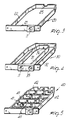
- the electric plate particularly for steam irons comprises a body, generally indicated by the reference numeral 1, which is preferably but not necessarily die-cast, and has a substantially flat lanceolate configuration, as is typical of electric plates for steam irons.
- An electric resistor 2 is incorporated inside the body 1 and extends substantially at the perimetral zones, with the exception of the rear zone.
- the cavity 3 has, in transverse cross section, a substantially rectangular configuration, so as to simplify manufacture.
- said cavity may be closed by inserts sealingly applicable at the rear face, which may be variously shaped according to requirements of use, so as to modify the characteristics and the functionality of said plate according to the user's requirements, without thereby having to modify the configuration of the body.
- the insert which is applied is structured so as to define the inlet for the introduction of water or steam inside the cavity.
- a plug insert 10 is provided which has defined therein an inlet 11 for the introduction of water or steam; in this solution the entire cavity is used without modifications which may vary its functionality.
- the cavity metal wool which has the function of retaining any water droplets, favouring a more rapid vaporization thereof also due to the fact that the surface area of contact between water and/or steam and the heated parts of the plate is increased.
- the body 1 defines on its lower ironing face a plurality of through holes, generally indicated by the reference numeral 5, which connect the cavity 3 with the exterior to allow the outward delivery of steam.
- the holes 5 which connect the cavity 3 with the exterior are provided directly at the region of the cavity 3.
- Said holes may be variously positioned on the plate in such a manner as to create different delivery zones.
- holes, indicated at 5a which affect the tip zone
- holes indicated at 5b which affect the central zone
- holes indicated at 5c which affect the lateral zones.
- the holes 5a, 5b and 5c are variously usable, as a function of the type of insert which is inserted.
- an insert generally indicated by the reference numeral 20
- an end crosspiece 21 defining the water and/or steam inlet, indicated by the reference numeral 11, having a perimetral border 22, which separates the zone affected by the holes 5a from the zone affected by the holes 5b and 5c.
- a depression or recess 25 is provided on the perimetral border 22 so as to allow the passage of the steam from the chamber where the holes 5b and 5c are provided to the chamber where the holes 5a are provided.
- the insert indicated at 30, has besides the end crosspiece an inner border 31 and an outer border 32.
- the inner border delimits an inner chamber for the steam, while the inner border in cooperation with the outer border delimits an aspiration chamber.
- an inlet 11 for the introduction of water and/or steam is connected to the inner chamber and an aspiration inlet, indicated at 35, is connected to the aspiration chamber arranged substantially at the holes 5c.
- a through channel 36 is furthermore provided which connects the inner chamber, provided substantially in the zone affected by the holes 5b, to the tip zone affected by the holes 5a.
- Figure 5 illustrates an embodiment in which the insert 40 has a plurality of transverse dividing walls 41 provided with upper recesses 42 which in practice provide a tortuous path which facilitates vaporization, thus making this type of insert particularly suitable for feeding the electric plate with water rather than steam.
- the invention achieves the proposed aims and in particular the fact is stressed that the provision of the plate with a rearwardly open inner cavity closed by inserts of various configurations allows the possibility of obtaining an improved functionality without modifying the configuration of the plate, but simply by modifying the type and the configuration of said insert, with the possibility therefore of variously employing the delivery holes which are distributed on the plate.
Landscapes
- Engineering & Computer Science (AREA)
- Textile Engineering (AREA)
- Health & Medical Sciences (AREA)
- Public Health (AREA)
- Irons (AREA)
Claims (8)
- Elektrische Grundplatte für Dampfbügeleisen mit einem im wesentlichen flachen Gehäuse (1), in das ein elektrischer Widerstand (2) eingebaut ist, wobei das Gehäuse (1) innen einen gegen die Rückseite dieses Gehäuses offenen Hohlraum (3) bildet und Einsätze (10, 20, 30, 40) umfaßt, die unterschiedliche Konfigurationen haben und so ausgebildet sind, daß sie diesen Hohlraum schließen und einen Einlaß (11) bilden, der das Einführen von Wasser und/oder Dampf in diesen Hohlraum (3) gestattet, wobei dieses Gehäuse (1) eine untere Bügelfläche bildet, in der eine Vielzahl von mit diesem Hohlraum (3) in Verbindung stehenden Löchern (5) zum Liefern von Dampf nach außen ausgebildet sind, dadurch gekennzeichnet, daß diese Löcher (5) in der unteren Bügelfläche des Gehäuses (1) direkt am Bereich des Hohlraums (3) derart vorgesehen sind, daß zusammen mit den unterschiedlich konfigurierten Einsätzen unterschiedliche Dampfzuführzonen erzeugt werden.
- Elektrische Grundplatte nach Anspruch 1, dadurch gekennzeichnet, daß diese Löcher (5) Löcher (5a, 5b, 5c) umfassen, die jeweils in einer Zone an der Spitze, einer mittleren Zone und einer seitlichen Zone dieses Gehäuses (1) verteilt sind.
- Elektrische Grundplatte nach einem der vorhergehenden Ansprüche, dadurch gekennzeichnet, daß einer dieser Einsätze gebildet wird durch einen Stopfeneinsatz (10), der zum Schließen des Hohlraums (3) anwendbar ist.
- Elektrische Grundplatte nach einem oder mehreren der vorhergehenden Ansprüche, dadurch gekennzeichnet, daß sie innerhalb des Hohlraums (3) Metallwolle umfaßt, derartiger Auslegung, daß die Wärmeaustauschfläche erhöht wird und Wasserpartikel eingefangen werden.
- Elektrische Grundplatte nach einem oder mehreren der vorhergehenden Ansprüche, dadurch gekennzeichnet, daß einer dieser Einsätze gebildet wird durch einen Einsatz (20) mit einem stirnseitigen Querstück (21), das einen Einlaß (11) für Wasser und/oder Dampf bildet, von dem ein Umfangsrand (22) abgeht, der in diesem Hohlraum (3) eine erste Kammer und eine zweite Kammer bildet, wobei diese erste Kammer die Löcher (5b, 5c) an diesen mittleren und seitlichen Zonen beeinflußt und diese zweite Kammer die Löcher (5a) in dieser Zone an der Spitze beeinflußt, wobei dieser Umfangsrand (22) eine Ausnehmung (25) bildet, die für die Verbindung zwischen dieser ersten und dieser zweiten Kammer ausgelegt ist.
- Elektrische Grundplatte nach einem der vorhergehenden Ansprüche, dadurch gekennzeichnet, daß einer dieser Einsätze gebildet wird durch einen Einsatz (30), der, ausgehend von diesem endseitigen Querstück einen Innenrand (31) und einen Außenrand (32) umfaßt, wobei dieser Innenrand (31) eine Innenkammer im wesentlichen an diesen Löchern (5b) an dieser zentralen Zone zwischen diesem Innenrand (31) und diesem äusseren Rand (32) begrenzt, wobei eine Ansaugkammer im wesentlichen diese Löcher (5c) an dieser seitlichen Zone beeinflußt, wobei diese Ansaugkammer mit einem Ansaugeinlaß (35) verbunden ist und diese innere Kammer mit diesem Einlaß (11) zum Einführen von Wasser und/oder Dampf verbunden ist.
- Elektrische Grundplatte nach einem der vorhergehenden Ansprüche, dadurch gekennzeichnet, daß einer dieser Einsätze gebildet wird durch einen Einsatz (40), der, in Zuordnung zu diesem endseitigen Querstück eine Vielzahl von Unterteilungswandungen (41) hat, die einander im wesentlichen senkrecht schneiden und an einem Rand mit Ausnehmungen (42) versehen sind, die eine Durchführung zur Verbindung zwischen den Sektoren oder Kammern ermöglichen, die durch diese Unterteilungswandungen (41) begrenzt sind, um einen gewundenen Weg für die Durchführung von Wasserdampf zu bilden.
- Elektrische Grundplatte nach einem oder mehreren der vorhergehenden Ansprüche, dadurch gekennzeichnet, daß einer dieser Einsätze (10, 20, 30, 40) eine Sohlenplatte hat, die so ausgelegt ist, daß sie wenigstens einige dieser Löcher (5) schließt.
Applications Claiming Priority (2)
| Application Number | Priority Date | Filing Date | Title |
|---|---|---|---|
| IT8721064U IT8721064V0 (it) | 1987-03-09 | 1987-03-09 | Piastra elettrica per stiratura a vapore. |
| IT2106487U | 1987-03-09 |
Publications (2)
| Publication Number | Publication Date |
|---|---|
| EP0281987A1 EP0281987A1 (de) | 1988-09-14 |
| EP0281987B1 true EP0281987B1 (de) | 1991-10-16 |
Family
ID=11176193
Family Applications (1)
| Application Number | Title | Priority Date | Filing Date |
|---|---|---|---|
| EP88103486A Expired EP0281987B1 (de) | 1987-03-09 | 1988-03-07 | Elektrische Sohle, insbesondere für Dampfbügeleisen |
Country Status (5)
| Country | Link |
|---|---|
| US (1) | US4854059A (de) |
| EP (1) | EP0281987B1 (de) |
| DE (1) | DE3865463D1 (de) |
| ES (1) | ES2026957T3 (de) |
| IT (1) | IT8721064V0 (de) |
Families Citing this family (17)
| Publication number | Priority date | Publication date | Assignee | Title |
|---|---|---|---|---|
| DE3901024A1 (de) * | 1989-01-13 | 1990-07-26 | Braun Ag | Elektrisches dampfbuegeleisen |
| USD330965S (en) | 1989-01-20 | 1992-11-10 | Calor S.A. | Sole for an iron |
| JP2769656B2 (ja) * | 1992-03-27 | 1998-06-25 | 日本甜菜製糖株式会社 | 農業用耐腐紙とその製法 |
| FR2691176B1 (fr) * | 1992-05-15 | 1995-09-08 | Moulinex Sa | Fer a repasser electrique a vapeur. |
| FR2704247B1 (fr) * | 1993-04-23 | 1995-11-10 | Moulinex Sa | Semelle d'un fer a repasser electrique a vapeur. |
| FR2711996B1 (fr) * | 1993-11-03 | 1995-12-15 | Seb Sa | Fer à repasser électrique comportant une semelle de repassage à faible inertie thermique. |
| AUPQ787700A0 (en) * | 2000-05-31 | 2000-06-22 | Mulyadi, Basuki | Ironing device |
| FR2890944B1 (fr) * | 2005-09-19 | 2007-10-26 | Seb Sa | Appareil electromenager comportant des moyens pour detecter l'ouverture d'un bouchon. |
| EP1944404A1 (de) * | 2006-12-18 | 2008-07-16 | Koninklijke Philips Electronics N.V. | Ein Gerät zur Versorgung mit überhitztem Wasser |
| US7926208B2 (en) | 2007-02-12 | 2011-04-19 | Applica Consumer Products, Inc. | Fast heat/fast cool iron with steam boiler |
| US7610701B2 (en) | 2007-02-12 | 2009-11-03 | Applica Consumer Products, Inc. | Iron with actively cooled soleplate |
| CN102132093B (zh) * | 2007-11-30 | 2014-03-12 | 皇家飞利浦电子股份有限公司 | 具有清洗特征的蒸汽设备 |
| ES2326512B1 (es) | 2008-04-10 | 2010-07-13 | Bsh Krainel, S.A. | Dispositivo de planchado a vapor con elementos simulados de abertura de salida de vapor. |
| ES2394682B1 (es) | 2010-11-11 | 2014-01-16 | BSH Electrodomésticos España S.A. | Aparato electrodoméstico y dispositivo para eliminar la cal de una caldera de dicho aparato electrodoméstico |
| JP6023077B2 (ja) * | 2011-01-03 | 2016-11-09 | コーニンクレッカ フィリップス エヌ ヴェKoninklijke Philips N.V. | 蒸気生成装置 |
| FR3033338B1 (fr) * | 2015-03-03 | 2017-02-24 | Seb Sa | Appareil electromenager de repassage comportant un filtre destine a retenir des particules de tartre transportees par la vapeur |
| CN109072536B (zh) * | 2016-04-26 | 2021-10-29 | 皇家飞利浦有限公司 | 具有用于钙化沉积物的收集舱的蒸汽熨斗 |
Family Cites Families (12)
| Publication number | Priority date | Publication date | Assignee | Title |
|---|---|---|---|---|
| US1649506A (en) * | 1925-10-08 | 1927-11-15 | Cannon Engineering Co | Electric iron |
| US2137387A (en) * | 1936-02-03 | 1938-11-22 | Chester M Chapin | Steaming iron |
| GB512071A (en) * | 1938-03-16 | 1939-08-29 | Stanley Booth | Improvements in or relating to hand irons |
| US2160421A (en) * | 1938-07-15 | 1939-05-30 | American Plush & Velvet Pressb | Iron |
| US2279179A (en) * | 1938-10-03 | 1942-04-07 | Edward P Schreyer | Electric iron and dampener |
| US2495397A (en) * | 1946-09-24 | 1950-01-24 | Albert J Weber | Condensation trap for steam irons |
| US2768455A (en) * | 1949-07-01 | 1956-10-30 | Gen Electric | Steam irons |
| US2795062A (en) * | 1953-12-09 | 1957-06-11 | Mc Graw Edison Co | Steam iron |
| DE1159897B (de) * | 1959-09-07 | 1963-12-27 | Licentia Gmbh | Dampfbuegeleisen |
| US3706146A (en) * | 1971-03-29 | 1972-12-19 | Bishop Freeman Co | Hand iron |
| US3949499A (en) * | 1974-12-19 | 1976-04-13 | General Electric Company | Removable tank iron |
| DE2530926B1 (de) * | 1975-07-11 | 1977-01-13 | Zeier H | Dampfbuegeleisen |
-
1987
- 1987-03-09 IT IT8721064U patent/IT8721064V0/it unknown
-
1988
- 1988-03-07 US US07/165,051 patent/US4854059A/en not_active Expired - Fee Related
- 1988-03-07 EP EP88103486A patent/EP0281987B1/de not_active Expired
- 1988-03-07 DE DE88103486T patent/DE3865463D1/de not_active Expired - Lifetime
- 1988-03-07 ES ES198888103486T patent/ES2026957T3/es not_active Expired - Lifetime
Also Published As
| Publication number | Publication date |
|---|---|
| US4854059A (en) | 1989-08-08 |
| EP0281987A1 (de) | 1988-09-14 |
| DE3865463D1 (en) | 1991-11-21 |
| ES2026957T3 (es) | 1992-05-16 |
| IT8721064V0 (it) | 1987-03-09 |
Similar Documents
| Publication | Publication Date | Title |
|---|---|---|
| EP0281987B1 (de) | Elektrische Sohle, insbesondere für Dampfbügeleisen | |
| USD1023450S1 (en) | Hair dryer | |
| USD949526S1 (en) | Shoe | |
| AU716301B2 (en) | Steam iron | |
| USD414319S (en) | Shoe sole | |
| USD450179S1 (en) | Slipper sock shoe | |
| USD452410S1 (en) | Microwave oven | |
| US3045371A (en) | Steam iron | |
| USD447616S1 (en) | Footwear sole | |
| USD433551S (en) | Laundry iron | |
| USD395980S (en) | Fryer | |
| USD416656S (en) | Electric steam iron | |
| USD1010962S1 (en) | Washing machine with clothes dryer | |
| USD1066831S1 (en) | Boot dryer | |
| EP0621365B1 (de) | Sohle eines elektrischen Dampfbügeleisens | |
| USD1035133S1 (en) | Hair dryer | |
| USD920747S1 (en) | Fork | |
| USD456122S1 (en) | Athletic shoe cover | |
| JPH0451204U (de) | ||
| USD381153S (en) | Soleplate for a steam iron | |
| USD1026409S1 (en) | Lower body garment | |
| CA111653S (en) | Washing machine | |
| US5983536A (en) | Electrical steam iron with steam channels | |
| USD1098386S1 (en) | Towel heating bucket | |
| US3335507A (en) | Heating and steam generating subassembly for a pressing iron |
Legal Events
| Date | Code | Title | Description |
|---|---|---|---|
| PUAI | Public reference made under article 153(3) epc to a published international application that has entered the european phase |
Free format text: ORIGINAL CODE: 0009012 |
|
| AK | Designated contracting states |
Kind code of ref document: A1 Designated state(s): CH DE ES FR GB IT LI NL |
|
| 17P | Request for examination filed |
Effective date: 19890222 |
|
| 17Q | First examination report despatched |
Effective date: 19900706 |
|
| GRAA | (expected) grant |
Free format text: ORIGINAL CODE: 0009210 |
|
| AK | Designated contracting states |
Kind code of ref document: B1 Designated state(s): CH DE ES FR GB IT LI NL |
|
| PG25 | Lapsed in a contracting state [announced via postgrant information from national office to epo] |
Ref country code: NL Effective date: 19911016 |
|
| REF | Corresponds to: |
Ref document number: 3865463 Country of ref document: DE Date of ref document: 19911121 |
|
| ET | Fr: translation filed | ||
| ITF | It: translation for a ep patent filed | ||
| NLV1 | Nl: lapsed or annulled due to failure to fulfill the requirements of art. 29p and 29m of the patents act | ||
| PGFP | Annual fee paid to national office [announced via postgrant information from national office to epo] |
Ref country code: GB Payment date: 19920325 Year of fee payment: 5 Ref country code: CH Payment date: 19920325 Year of fee payment: 5 |
|
| PGFP | Annual fee paid to national office [announced via postgrant information from national office to epo] |
Ref country code: ES Payment date: 19920331 Year of fee payment: 5 |
|
| REG | Reference to a national code |
Ref country code: ES Ref legal event code: FG2A Ref document number: 2026957 Country of ref document: ES Kind code of ref document: T3 |
|
| PGFP | Annual fee paid to national office [announced via postgrant information from national office to epo] |
Ref country code: DE Payment date: 19920529 Year of fee payment: 5 |
|
| PLBE | No opposition filed within time limit |
Free format text: ORIGINAL CODE: 0009261 |
|
| STAA | Information on the status of an ep patent application or granted ep patent |
Free format text: STATUS: NO OPPOSITION FILED WITHIN TIME LIMIT |
|
| 26N | No opposition filed | ||
| PG25 | Lapsed in a contracting state [announced via postgrant information from national office to epo] |
Ref country code: GB Effective date: 19930307 |
|
| PG25 | Lapsed in a contracting state [announced via postgrant information from national office to epo] |
Ref country code: ES Free format text: LAPSE BECAUSE OF NON-PAYMENT OF DUE FEES Effective date: 19930308 |
|
| PG25 | Lapsed in a contracting state [announced via postgrant information from national office to epo] |
Ref country code: LI Effective date: 19930331 Ref country code: CH Effective date: 19930331 |
|
| PGFP | Annual fee paid to national office [announced via postgrant information from national office to epo] |
Ref country code: FR Payment date: 19930331 Year of fee payment: 6 |
|
| GBPC | Gb: european patent ceased through non-payment of renewal fee |
Effective date: 19930307 |
|
| REG | Reference to a national code |
Ref country code: CH Ref legal event code: PL |
|
| PG25 | Lapsed in a contracting state [announced via postgrant information from national office to epo] |
Ref country code: DE Effective date: 19931201 |
|
| PG25 | Lapsed in a contracting state [announced via postgrant information from national office to epo] |
Ref country code: FR Effective date: 19941130 |
|
| REG | Reference to a national code |
Ref country code: FR Ref legal event code: ST |
|
| REG | Reference to a national code |
Ref country code: ES Ref legal event code: FD2A Effective date: 19990201 |
|
| PG25 | Lapsed in a contracting state [announced via postgrant information from national office to epo] |
Ref country code: IT Free format text: LAPSE BECAUSE OF NON-PAYMENT OF DUE FEES Effective date: 20050307 |