EP0281995A2 - Chauffe-eau instantané électrique - Google Patents
Chauffe-eau instantané électrique Download PDFInfo
- Publication number
- EP0281995A2 EP0281995A2 EP88103596A EP88103596A EP0281995A2 EP 0281995 A2 EP0281995 A2 EP 0281995A2 EP 88103596 A EP88103596 A EP 88103596A EP 88103596 A EP88103596 A EP 88103596A EP 0281995 A2 EP0281995 A2 EP 0281995A2
- Authority
- EP
- European Patent Office
- Prior art keywords
- water heater
- contact
- instantaneous water
- heater according
- snap
- Prior art date
- Legal status (The legal status is an assumption and is not a legal conclusion. Google has not performed a legal analysis and makes no representation as to the accuracy of the status listed.)
- Withdrawn
Links
- XLYOFNOQVPJJNP-UHFFFAOYSA-N water Substances O XLYOFNOQVPJJNP-UHFFFAOYSA-N 0.000 claims abstract description 26
- 238000010438 heat treatment Methods 0.000 claims abstract description 7
- 230000005405 multipole Effects 0.000 claims abstract description 4
- 238000000034 method Methods 0.000 claims abstract description 3
- 238000010079 rubber tapping Methods 0.000 claims abstract description 3
- 238000004519 manufacturing process Methods 0.000 claims description 3
- 238000005096 rolling process Methods 0.000 claims description 2
- 230000001960 triggered effect Effects 0.000 claims 1
- 239000002184 metal Substances 0.000 description 2
- 238000011161 development Methods 0.000 description 1
- 230000018109 developmental process Effects 0.000 description 1
- 230000000977 initiatory effect Effects 0.000 description 1
- 230000007257 malfunction Effects 0.000 description 1
- 239000000463 material Substances 0.000 description 1
Images

Classifications
-
- H—ELECTRICITY
- H01—ELECTRIC ELEMENTS
- H01H—ELECTRIC SWITCHES; RELAYS; SELECTORS; EMERGENCY PROTECTIVE DEVICES
- H01H37/00—Thermally-actuated switches
- H01H37/002—Thermally-actuated switches combined with protective means
-
- F—MECHANICAL ENGINEERING; LIGHTING; HEATING; WEAPONS; BLASTING
- F24—HEATING; RANGES; VENTILATING
- F24H—FLUID HEATERS, e.g. WATER OR AIR HEATERS, HAVING HEAT-GENERATING MEANS, e.g. HEAT PUMPS, IN GENERAL
- F24H9/00—Details
- F24H9/20—Arrangement or mounting of control or safety devices
- F24H9/2007—Arrangement or mounting of control or safety devices for water heaters
- F24H9/2014—Arrangement or mounting of control or safety devices for water heaters using electrical energy supply
- F24H9/2028—Continuous-flow heaters
-
- H—ELECTRICITY
- H01—ELECTRIC ELEMENTS
- H01H—ELECTRIC SWITCHES; RELAYS; SELECTORS; EMERGENCY PROTECTIVE DEVICES
- H01H35/00—Switches operated by change of a physical condition
- H01H35/24—Switches operated by change of fluid pressure, by fluid pressure waves, or by change of fluid flow
-
- H—ELECTRICITY
- H01—ELECTRIC ELEMENTS
- H01H—ELECTRIC SWITCHES; RELAYS; SELECTORS; EMERGENCY PROTECTIVE DEVICES
- H01H5/00—Snap-action arrangements, i.e. in which during a single opening operation or a single closing operation energy is first stored and then released to produce or assist the contact movement
- H01H5/04—Energy stored by deformation of elastic members
- H01H5/18—Energy stored by deformation of elastic members by flexing of blade springs
-
- H—ELECTRICITY
- H01—ELECTRIC ELEMENTS
- H01H—ELECTRIC SWITCHES; RELAYS; SELECTORS; EMERGENCY PROTECTIVE DEVICES
- H01H9/00—Details of switching devices, not covered by groups H01H1/00 - H01H7/00
- H01H9/0072—Details of switching devices, not covered by groups H01H1/00 - H01H7/00 particular to three-phase switches
Definitions
- the invention relates to an electric instantaneous water heater according to the preamble of patent claim 1.
- an electric instantaneous water heater of this type is known, in which the heating circuit is closed with the initiation of the tapping process via a multi-pole operating switch contact device controlled by a water switch.
- the multi-pole switch contact device consists of a triple snap spring contact arrangement which is actuated via a lever system which is operatively connected to the water switch.
- a safety switching device for a water heater of the aforementioned type is known from DE-B-15 40 906 and DE-B-22 58 850.
- the operating switch contact device and the safety switching device are two completely separate structural units or components of the instantaneous water heater, which require a corresponding outlay in terms of production and in the use of materials and time in final assembly.
- the invention has for its object to reduce the effort outlined above and to provide a structurally simplified switching device for a water heater of the type mentioned.
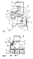
- Fig. 1 of the drawing denotes the indicated differential pressure socket of a so-called water switch, not shown, which can be connected to the cold water supply line of an electrically heated water heater for three-phase connection.
- a lifting diaphragm which is raised by the differential pressure when water is drawn off and which raises or pushes a switching plunger 2.
- the shift plunger 2 works together with a lever system 3, which consists of a pivotably mounted angle lever 4 and three pivotable, multi-arm shift levers 5.
- Each of the shift levers 5 works together with a contacted snap spring 6 and holds when the Water heater whose contact 7 in the open position.
- the contacted snap spring 6 is part of a U-shaped one-piece snap spring contact arrangement 8, the other contacted snap spring 9 is held with its contact 10 by the lever arm 11 of a further lever system 12 during normal operation in the circuit closed position.
- the lever system 12 is also pivotally mounted and is latched to a two-armed lever 14 held under the action of a spring element 13.
- One arm 14 ⁇ of the two-armed lever 14 works with an electric magnet 15 of a safety switching device which can be placed at an excess temperature, while the other arm 14 ⁇ is influenced by an occurrence of overpressure in the flow system of the flow heater, which is responsive to the overpressure safety device 16.
- the snap spring contact arrangement 8, of which three are required in a water heater with three-phase connection, are held on an insulating support 17 and separated from one another by intermediate webs 18, 18 18.
- the two U-legs of the snap or spring contact arrangement 8, of which one 6 carries the movable contact 7 of the operating switch contact device, the other 9 carries the movable contact 10 of the safety switching device, are connected to one another by a flat web 19.
- the contact arrangement 8 is fixed and fastened to the insulating support 17 with the flat web 19.
- the insulating support 17 practically represents the connecting part between the operating switch contact device on the one hand and the safety switching device on the other.
- the U-shaped contact arrangement 8 In the manufacture of the U-shaped contact arrangement 8 from a rolled metal strip, it is particularly expedient that its snap or spring springs placed or running transversely to the rolling device of the metal strip . be formed. As a result, the relaxation behavior (flexural fatigue strength) that works better in this direction is used.
- the described device works as follows: With a corresponding water flow rate, the lifting diaphragm in the differential pressure cell 1 is raised accordingly by the dynamic pressure that occurs, and the switching plunger 2 is thus brought upwards. The movement of the switching plunger 2 is on the angle lever 4 transmitted, which thereby pivoted about its pivot point and thereby also pivoted the shift lever 5 held in operative connection with it about its pivot point. The contacted snap spring 6 of the contact arrangement 8 is relieved and goes into the closed position with the stationary counter contact 7 ⁇ . The heating circuit for the instantaneous water heater is closed.
- the two-armed lever 14 of the safety switching device is actuated either by the electro-magnet 15 receiving voltage at excess temperature, which triggers the lever system 12 holding the movable contact 10 ⁇ in the closed position and the snap spring 9 with its contact 10 abruptly in the contact open position snaps or jumps.
Landscapes
- Engineering & Computer Science (AREA)
- Physics & Mathematics (AREA)
- Thermal Sciences (AREA)
- Chemical & Material Sciences (AREA)
- Combustion & Propulsion (AREA)
- Mechanical Engineering (AREA)
- General Engineering & Computer Science (AREA)
- Fluid Mechanics (AREA)
- Instantaneous Water Boilers, Portable Hot-Water Supply Apparatuses, And Control Of Portable Hot-Water Supply Apparatuses (AREA)
- Cookers (AREA)
Applications Claiming Priority (2)
| Application Number | Priority Date | Filing Date | Title |
|---|---|---|---|
| DE3707967 | 1987-03-12 | ||
| DE19873707967 DE3707967A1 (de) | 1987-03-12 | 1987-03-12 | Elektrischer durchlauferhitzer |
Publications (2)
| Publication Number | Publication Date |
|---|---|
| EP0281995A2 true EP0281995A2 (fr) | 1988-09-14 |
| EP0281995A3 EP0281995A3 (fr) | 1990-07-04 |
Family
ID=6322868
Family Applications (1)
| Application Number | Title | Priority Date | Filing Date |
|---|---|---|---|
| EP88103596A Withdrawn EP0281995A3 (fr) | 1987-03-12 | 1988-03-08 | Chauffe-eau instantané électrique |
Country Status (2)
| Country | Link |
|---|---|
| EP (1) | EP0281995A3 (fr) |
| DE (1) | DE3707967A1 (fr) |
Cited By (1)
| Publication number | Priority date | Publication date | Assignee | Title |
|---|---|---|---|---|
| DE4234579A1 (de) * | 1992-10-14 | 1994-04-21 | Heinrich Kissling Gmbh & Co Kg | Schalteinrichtung |
Families Citing this family (5)
| Publication number | Priority date | Publication date | Assignee | Title |
|---|---|---|---|---|
| DE4227358C2 (de) * | 1992-08-19 | 1995-06-22 | Kulmbacher Klimageraete | Vorrichtung zum Schalten der Heizenergiezufuhr eines elektrischen Durchlauferhitzers |
| DE4309117C2 (de) * | 1993-03-23 | 1997-09-04 | Bosch Gmbh Robert | Elektrisch beheizter Wassererhitzer, insbesondere Durchlauferhitzer |
| DE4401670C2 (de) * | 1994-01-21 | 1995-11-30 | Kulmbacher Klimageraete | Anordnung zum Steuern der Heizenergiezufuhr zu den Heizwicklungen eines elektrischen Durchlauferhitzers |
| DE19635973C2 (de) * | 1996-09-05 | 2000-02-10 | Stiebel Eltron Gmbh & Co Kg | Netzspannungs-Schaltvorrichtung, insbesondere für einen Durchlauferhitzer |
| DE19919949C5 (de) * | 1999-04-30 | 2013-03-07 | BSH Bosch und Siemens Hausgeräte GmbH | Vorrichtung mit einem Sicherheitsschalter |
Family Cites Families (12)
| Publication number | Priority date | Publication date | Assignee | Title |
|---|---|---|---|---|
| BE488906A (fr) * | 1948-05-10 | |||
| DE1020130B (de) * | 1956-07-06 | 1957-11-28 | Eckerfeld Alfred | Elektrischer Fluessigkeitserhitzer |
| DE1062845B (de) * | 1957-12-14 | 1959-08-06 | Eckerfeld Alfred | Elektrischer Fluessigkeitserhitzer |
| DE1179314B (de) * | 1962-10-01 | 1964-10-08 | Licentia Gmbh | Elektrischer Durchlauferhiter |
| DE1540906B2 (de) * | 1965-03-29 | 1972-07-20 | Licentia Patent-Verwaltungs-Gmbh, 6000 Frankfurt | Sicherheitsschaltung fuer elektrisch beheizte durchlauferhitzer |
| FR1488362A (fr) * | 1966-05-31 | 1967-07-13 | Cotherm Sa | Perfectionnements aux dispositifs thermostatiques de réglage d'une installation de chauffe électrique |
| US3781520A (en) * | 1971-12-06 | 1973-12-25 | Gardom & Lock Ltd | Electric instantaneous water heater |
| DE2258850B2 (de) * | 1972-12-01 | 1977-03-24 | Licentia Patent-Verwaltungs-Gmbh, 6000 Frankfurt | Sicherheitsschalteinrichtung fuer einen elektrisch beheizten durchlauferhitzer |
| DE2625266C2 (de) * | 1976-06-04 | 1983-06-16 | E.G.O. Elektro-Geräte AG, 6301 Zug | Schnappschalter mit einer Schnappfeder |
| DE3039383A1 (de) * | 1980-10-18 | 1982-05-19 | Stiebel Eltron Gmbh & Co Kg, 3450 Holzminden | Durchlauferhitzer |
| US4400628A (en) * | 1982-02-16 | 1983-08-23 | General Electric Company | Control device and method of making |
| DE3438304C2 (de) * | 1984-10-19 | 1986-10-09 | Leopold Kostal GmbH & Co KG, 5880 Lüdenscheid | Elektrischer Schnappschalter |
-
1987
- 1987-03-12 DE DE19873707967 patent/DE3707967A1/de not_active Withdrawn
-
1988
- 1988-03-08 EP EP88103596A patent/EP0281995A3/fr not_active Withdrawn
Cited By (1)
| Publication number | Priority date | Publication date | Assignee | Title |
|---|---|---|---|---|
| DE4234579A1 (de) * | 1992-10-14 | 1994-04-21 | Heinrich Kissling Gmbh & Co Kg | Schalteinrichtung |
Also Published As
| Publication number | Publication date |
|---|---|
| DE3707967A1 (de) | 1988-09-22 |
| EP0281995A3 (fr) | 1990-07-04 |
Similar Documents
| Publication | Publication Date | Title |
|---|---|---|
| EP1203385A1 (fr) | Ensemble coupe-circuit multipolaire pour jeux de barres collectrices | |
| DE2917557C2 (de) | Wärmeschutzschalter | |
| EP0078458A2 (fr) | Appareil de commutation pour un dispositif consommateur devant être connecté à trois pôles | |
| DE3707967A1 (de) | Elektrischer durchlauferhitzer | |
| DE2618360B2 (de) | Mit einem Schalter versehener Sicherungssockel für Schmelzeinsätze | |
| DE19702780C1 (de) | Hochspannungs-Hochleistungs-Sicherung | |
| DE4401670A1 (de) | Anordnung zum Steuern der Heizenergiezufuhr zu den Heizwicklungen eines elektrischen Durchlauferhitzers | |
| DE2551873C2 (de) | Endschalter | |
| DE2626003A1 (de) | Mehrpoliger druckschalter mit ueberstromausloesung und unterspannungs- bzw. phasenausfallschutz | |
| DE2435151A1 (de) | Elektrischer leistungsregler | |
| DE69501321T2 (de) | Sicherheitsschalter, insbesondere für elektrische Haushaltsgeräte | |
| DE1802457C3 (de) | Steckvorrichtung | |
| DE3830719A1 (de) | Elektrischer durchlauferhitzer | |
| DE69827992T2 (de) | Sicherungshaltervorrichtung von der Art einer Schachtsicherung für elektrische Geräte | |
| CH693051A5 (de) | Widerstandsanordnung zu einem zum Schalten von kapazitiven Lasten bestimmten elektromagnetischen Schaltgerät. | |
| DE2509828C2 (de) | Feuersichere elektrische Anschlußvorrichtung | |
| DE2530226C3 (de) | Endschalter | |
| EP1926112A1 (fr) | Système de contact électrique pour un appareil de coupure électrique | |
| DE2934149C2 (de) | Niederspannungs-Lastschalter mit Sicherung. | |
| DE2348297C2 (de) | Kleintransformator mit einer Schutzanordnung gegen thermische Überlastung | |
| DE29614028U1 (de) | Schnappschalter mit Gehäuse | |
| DE1538447C3 (de) | Thermisches Oberstromrelais mit Phasenausfallschutz | |
| DE341614C (de) | Anlassschalter fuer Wechselstrommotoren | |
| DE545889C (de) | Als elektrische Kontaktvorrichtung ausgebildeter Schalthebel, insbesondere fuer Kraftfahrzeuge | |
| DE972703C (de) | Elektrische Selbstschalteranordnung fuer Futterdaempfer |
Legal Events
| Date | Code | Title | Description |
|---|---|---|---|
| PUAI | Public reference made under article 153(3) epc to a published international application that has entered the european phase |
Free format text: ORIGINAL CODE: 0009012 |
|
| AK | Designated contracting states |
Kind code of ref document: A2 Designated state(s): AT BE CH DE FR GB IT LI LU NL |
|
| PUAL | Search report despatched |
Free format text: ORIGINAL CODE: 0009013 |
|
| AK | Designated contracting states |
Kind code of ref document: A3 Designated state(s): AT BE CH DE FR GB IT LI LU NL |
|
| 17P | Request for examination filed |
Effective date: 19901204 |
|
| 17Q | First examination report despatched |
Effective date: 19930326 |
|
| STAA | Information on the status of an ep patent application or granted ep patent |
Free format text: STATUS: THE APPLICATION IS DEEMED TO BE WITHDRAWN |
|
| 18D | Application deemed to be withdrawn |
Effective date: 19930806 |