EP0282028B1 - Übertragungssystem mit Vielfachzugriff - Google Patents
Übertragungssystem mit Vielfachzugriff Download PDFInfo
- Publication number
- EP0282028B1 EP0282028B1 EP88103712A EP88103712A EP0282028B1 EP 0282028 B1 EP0282028 B1 EP 0282028B1 EP 88103712 A EP88103712 A EP 88103712A EP 88103712 A EP88103712 A EP 88103712A EP 0282028 B1 EP0282028 B1 EP 0282028B1
- Authority
- EP
- European Patent Office
- Prior art keywords
- communication
- channel
- allocated
- common signalling
- signalling channel
- Prior art date
- Legal status (The legal status is an assumption and is not a legal conclusion. Google has not performed a legal analysis and makes no representation as to the accuracy of the status listed.)
- Expired - Lifetime
Links
- 230000006854 communication Effects 0.000 title claims description 246
- 238000004891 communication Methods 0.000 title claims description 246
- 230000011664 signaling Effects 0.000 claims description 78
- 230000005540 biological transmission Effects 0.000 description 50
- 238000010276 construction Methods 0.000 description 10
- RTZKZFJDLAIYFH-UHFFFAOYSA-N Diethyl ether Chemical compound CCOCC RTZKZFJDLAIYFH-UHFFFAOYSA-N 0.000 description 6
- 230000007175 bidirectional communication Effects 0.000 description 6
- 238000000034 method Methods 0.000 description 4
- 230000003321 amplification Effects 0.000 description 2
- 238000012937 correction Methods 0.000 description 2
- 230000000694 effects Effects 0.000 description 2
- 238000003199 nucleic acid amplification method Methods 0.000 description 2
- 238000012545 processing Methods 0.000 description 2
- 241001116459 Sequoia Species 0.000 description 1
- 239000000969 carrier Substances 0.000 description 1
- 238000012986 modification Methods 0.000 description 1
- 230000004048 modification Effects 0.000 description 1
- 230000008054 signal transmission Effects 0.000 description 1
Images




Classifications
-
- H—ELECTRICITY
- H04—ELECTRIC COMMUNICATION TECHNIQUE
- H04W—WIRELESS COMMUNICATION NETWORKS
- H04W72/00—Local resource management
- H04W72/04—Wireless resource allocation
- H04W72/044—Wireless resource allocation based on the type of the allocated resource
-
- H—ELECTRICITY
- H04—ELECTRIC COMMUNICATION TECHNIQUE
- H04B—TRANSMISSION
- H04B7/00—Radio transmission systems, i.e. using radiation field
- H04B7/14—Relay systems
- H04B7/15—Active relay systems
- H04B7/204—Multiple access
- H04B7/212—Time-division multiple access [TDMA]
-
- H—ELECTRICITY
- H04—ELECTRIC COMMUNICATION TECHNIQUE
- H04W—WIRELESS COMMUNICATION NETWORKS
- H04W72/00—Local resource management
- H04W72/04—Wireless resource allocation
- H04W72/044—Wireless resource allocation based on the type of the allocated resource
- H04W72/0446—Resources in time domain, e.g. slots or frames
-
- H—ELECTRICITY
- H04—ELECTRIC COMMUNICATION TECHNIQUE
- H04W—WIRELESS COMMUNICATION NETWORKS
- H04W72/00—Local resource management
- H04W72/04—Wireless resource allocation
- H04W72/044—Wireless resource allocation based on the type of the allocated resource
- H04W72/0453—Resources in frequency domain, e.g. a carrier in FDMA
-
- H—ELECTRICITY
- H04—ELECTRIC COMMUNICATION TECHNIQUE
- H04W—WIRELESS COMMUNICATION NETWORKS
- H04W76/00—Connection management
- H04W76/10—Connection setup
-
- H—ELECTRICITY
- H04—ELECTRIC COMMUNICATION TECHNIQUE
- H04W—WIRELESS COMMUNICATION NETWORKS
- H04W76/00—Connection management
- H04W76/30—Connection release
Definitions
- the present invention relates to a multiple access communication system for performing the communication between a plurality of communication units using a plurality of communication channels and a common signalling channel for establishing and releasing the communication channels, wherein at least one signalling channel carrier frequency is allocated to the common signalling channel, and communication channel carrier frequencies which are different from the signalling channel carrier frequency are allotted to the communication channels.
- Such multiple access communication system is disclosed in H.S. Alkhatib "The EENET: A Broadband Local Area Network", Interfaces in Computing, 2 (1984), 321-348 (Elsevier Sequoia, The Netherlands).
- the EENET is a local area computer network designed explicitly for real time applications and employs a shared multi-access bus with a branching-tree topology called the extended ether which is divided into two frequency subchannels, the extended ether channel (EEC) and the reservation channel (RC).
- the EEC is the data channel interconnecting all modes over the extended ether.
- the EEC in turn is divided into a number of frequency subchannels according to the maximum number of nodes to be used in the system. To establish a connection between a source node and a destination node, one of the available EEC frequency circuits is reserved by the source node through the broadcast RC.
- carrier frequencies or time slots are generally utilized as communication resources between plural communication units, and plural communication channels are simultaneously required for communicating therebetween.
- FDMA Frequency Division Multiple Access
- TDMA Time Division Multiple Access
- the typical example of the FDMA system is the so called Single Channel Per Carrier (SCPC)-FDMA system, in which a carrier frequency is selected from pooled vacant frequencies to be used as a communication channel.
- SCPC Single Channel Per Carrier
- the TDMA system is the system in which a time slot is selected from pooled vacant time slots to be utilized as a communication channel.
- connection and disconnection of communication channels are done by using a common signalling channel, separately disposed from the communication channels.
- a common signalling channel a specified carrier frequency, which is different from the communication channel carrier frequencies, is allotted to as the common signalling channel
- a specified time slot which is different from the communication time slots, is allocated to as the common signalling channel.
- a transmitting amplifier When the plurality of carrier frequencies are simultaneously transmitted, a transmitting amplifier simultaneously amplifies a plurality of signals of carrier frequency, which is a multiple frequency amplifying operation. Accordingly, it is necessary to use a linear operating region with the transmitting amplifier having a large operating margin so as to avoid the generation of a distorsion of intermodulation product caused by a nonlinearity in operation of the transmitting amplifier. In such a situation, the transmitting amplifier is used in a state in which the efficiency is ultimately low. Accordingly, it is necessary to use a transmitter having a large electric power to secure a predetermined transmitting power in accordance with link budget, thereby increasing the cost of the system.
- TDMA Time Division Multiple Access
- traffic between a plurality of communication units is treated by the common signalling channel and the communication channel at one frequency so that the transmission rate is ultimately high and the occupied band is increased. Accordingly, it is necessary to dispose a transmitter having a large power and an antenna having a large diameter to transmit signals in a wide band in a predetermined power density. Further, digital circuits disposed in control sections, etc., of the TDMA system become complicated and the cost of the system is greatly increased.
- the transmission rate of one channel allocated to one carrier frequency is fixed so that a plurality of carrier frequencies must be used to communicate at a carrier speed faster than a predetermined carrier speed and simultaneously communicate with a plurality of communicating units bi-directionally.
- a plurality of time slots can be used from multiplexed time slots so that it is possible to simultaneously communicate with a plurality of communication units bi-directionally at various speeds.
- this system is uneconomical for a user's communicating unit communicated at a low speed.
- a number of communication channel time slots are fixedly multiplexed at one carrier frequency so that the transmission rate is much faster than in the SCPC-FDMA system.
- the receiving noiseband is widened and the receiving channel quality is reduced so that it is necessary to increase the transmitting power and use an antenna having a large diameter, thereby making the TDMA control complicated and increasing the cost of the user's communication unit.
- the SCPC-FDMA system it is economical for a user treating only one communication channel at a predetermined speed, but it is not suitable for communications at various speeds corresponding to simultaneous bi-directional communications with a plurality of communication units or multi-media which have been required by users.
- the TDMA system it is easy to perform simultaneous bi-directional communications with a plurality of communication units or communicate at various speeds, but the user's communication unit is expensive and, in particular, the communication unit is greatly uneconomical for a user who does not need the simultaneous bi-directional communication with a plurality of communication units.
- a number of communication units are disposed in the TDMA system so that the multiplex is increased as the traffic amount is increased, thereby increasing the cost of the user's communication unit irrespective of the user's requirement.
- an object of the present invention is to provide a multiple access communication system which can simultaneously communicate with a plurality of communication units and is economical.
- the present invention resides in a multiple access communication system for performing the communication between a plurality of communication units (3; A-N) using a plurality of communication channels and a common signalling channel for establishing and releasing the commnunication channels, wherein at least one signalling channel carrier frequency (FO) is allocated to the common signalling channel; and communication channel carrier frequencies (Fl-Fn) which are different from the signalling channel carrier frequency (FO), are allotted to the communication channels; characterized by a time frame composed of first (T1) and second (T2) time slots for the common signalling channel and the communication channels, respectively; such that the first time slot (T1) is allocated only to the common signalling channel, and the second time slot (T2) is allocated at least to the communication channels.
- T1 first
- T2 second time slot
- the second time slot (T2) is divided into a plurality of time sections (t1, t2,...) in order to communicate between one communication unit (e.g., A) and another communication unit (e.g., X).
- one communication unit e.g., A
- another communication unit e.g., X
- the first time slot (T1) is preferably allocated to the common signalling channel is first used to establish a new communication channel relating to a communication unit, for which a communication channel has already been established.
- the second time slot (T2) is preferably also allocated to the common signalling channel for firstly releasing the communication channel, and for secondly transmitting the common signalling channel carrier frequency, such that the communication channel carrier frequency (Fl,...,Fn) and the common signalling channel carrier frequency (FO) are not simultaneously transmitted.
- the second time slot (T2) is also allocated to the common signalling channel, and is used to establish a communication channel related to a communication unit, to which no communication channel has yet been established.
- At least one of the first and second time slots (T1,T2) allocated to the common signalling channel is divided into a plurality of time sections in order to receive a plurality of common signalling channels.
- the multiple access communication system may have a plurality of carrier frequencies, which are allocated to the common signalling channel.
- Fig. 1 is a view showing the general construction of a satellite communication system to which the present invention is applied.
- a multiple access communication is performed through a satellite 1 by a network control unit 2 and a plurality of communication units 3 designated by A to N.
- the network control unit 2 sets and releases a communication channel required between the communication units 3 in accordance with the requirement of communication and the release thereof.
- the communication system shown in Fig. 2 is used when the communication of the system is performed as shown in Fig. 1.
- a carrier frequency F0 is allocated to a common signalling channel
- carrier frequencies Fl to Fn are allocated to a communication channel.
- the common signalling channel and the communication channel constitute a time frame composed of first and second time slots T1 and T2.
- the first time slot T1 is used for only the common signalling channel
- the second time slot T2 is used for the common signalling channel with respect to the carrier frequency F0 in this example, and is used for the communication channel with respect to the carrier frequencies Fl to Fn.
- the second time slot T2 in the communication channel with respect to the carrier frequencies Fl to Fn is divided into two time sections t1 and t2.
- the first time section t1 is used for the communication between the communication units A and B with respect to the second time slot T2 at the carrier frequency Fl.
- the communication channel set for the communication between the communication units A and B is called Fl-t1 in the following description.
- the first time slot T1 allocated to the common signalling channel is not used to set a communicating channel with respect to the communication requirement related to another communicating unit X different from the communicating units A and B, but is preferably used first to set a new communicating channel not related to the communication between units A and B for which the communication channel has been already decided, namely, a new communication channel with respect to the communication requirement between the communicating units A and B and the other communication unit X.
- the carrier frequencies Fl to Fn of the communication channel and the carrier frequency F0 of the common signalling channel are not simultaneously transmitted as in the conventional SCPC-FDMA system, so that it is not necessary to perform a multiple frequency amplification having low efficiency in the transmitting amplifier.
- the requirement for releasing the communication is transmitted to the network control unit 2 through the second time slot T2 allocated to the common signalling channel, preferably by the time section t1.
- the communication channel Fl-t1 is released by the instructions from the second time slot T2 allocated to the common signalling channel, preferably the time section t1.
- the second time slot T2 is also allocated to the communication channel.
- the carrier frequencies Fl to Fn of the communication channel and the carrier frequency F0 of the common signalling channel are not simultaneously transmitted since the communication has been completed, so that it is not necessary to perform a multiple frequency amplification in the transmitting amplifier.
- the second time slot T2 allocated to the common signalling channel is used to set the communication channel, and either one of the carrier frequencies F2 to Fn except for the carrier frequency F1 is used as a communication channel.
- the plurality of carrier frequencies are allocated to the communication channel in this way, the time multiplicity of every carrier frequency is greatly reduced in comparison with the TDMA system. Accordingly, the signal transmission rate does not become ultimately high, and the band is not greatly widened so that the burden on the function of the transmitting amplifier and the antenna is reduced and the control circuitry is simplified.
- the second time slot T2 allocated to the common signalling channel is used to release the communication channel already set, and to set a new communication channel for a communication unit for which a communication channel has not been set at all.
- the second time slot T2 is preferably used first to especially release the communication channel.
- the present invention is not limited to the embodiment mentioned above.
- the second time slot T2 allocated to the communicating channel is divided into two time sections t1 and t2 in the above embodiment, but may be divided into more than three time sections.
- one carrier frequency is allocated to the common signalling channel, but a plurality of carrier frequencies may be allocated to the common signalling channel such that the frequencies are different from each other with respect to the requirements and instructions.
- the bi-directional communication between the communication units A and B is performed by using the communication channel of the same carrier frequency Fl in the above embodiment, but carrier frequencies different from each other may be used in the cases of the A to B direction and the B to A direction.
- At least one of the first and second time slots T1 and T2 allocated to the common signalling channel may be further divided into a plurality of time slots to receive a plurality of common signalling channels.
- a plurality of carrier frequencies different from a carrier frequency allocated to a common signalling channel are allocated to a communication channel.
- the common signalling channel and the communication channel constitute a time frame composed of two time slots.
- a first time slot is allocated to only the common signalling channel, and a second time slot is allocated to at least the communication channel.
- the second time slot allocated to the communication channel is divided into a plurality of time slots to receive a plurality of communication channels so that the common signalling channel can be used at any time, and a new communication channel can be set even during the communication in accordance with another communicating requirement, thereby performing a simultaneous transmission with a plurality of communication units and switching to a communication unit which can communicate prior to the other units.
- the present invention provides an economical multiple access communication system for enabling simultaneous communication with a plurality of partners.
- Fig. 3A shows a star-type communicating network to which the present invention is applied in another embodiment thereof.
- Each of user's communication units A to H call a line control unit LCU through a common signalling channel and require a transmission rate and a packet length of a communication channel through the common signalling channel.
- the line control unit LCU allocates to each of the user's communication units a carrier frequency used in the communication channel, the transmission rate and packet length and a packet position per carrier frequency through the common signalling channel based on the requirement from each of the user's communication units, thereby setting the communication channel.
- Each of the user's communication units communicates with another communication unit through the allocated communication channel.
- each of the user's communication units informs the line control unit of the completion through the common signalling channel, and of releasing the communication channel through the common signalling channel.
- Fig. 4 shows the relation between the selective transmission rate and packet length in the communication channel per carrier frequency.
- the communication channel frame in mode 2 is divided into two unit packets having packet length L/2 and transmission rate 2Fw where the unit of information transmission is designated by P.
- the communication channel frame in mode 3 is divided into four unit packets having packet length L/4 and transmission rate 4Fw.
- Each of the user's communication units of Fig. 3A selects communication channel transmission parameters of a plurality of transmission rates and packet lengths prepared in advance as shown in Fig. 4, and requires the allocation of the line to the line control unit LCU through the common signalling channel.
- the mode 1 of Fig. 4(a) is required.
- the mode 2 of Fig. 4(b) is required.
- the mode 3 of Fig. 4(c) is required.
- the mode 2 of Fig. 4(c) is required.
- a simultaneous bi-directional communication between a plurality of communication units and a communication at multiple speeds can be performed when the user's communication units select and require at least the communication channel transmission parameters of a plurality of transmission rates and packet lengths prepared in advance. Further, the system can easily correspond to the increase of the number of user's communication units and the traffic amount without the increase of the multiplicity.
- the transmission parameters are selected and required by the user's communication units.
- each of the user's communication units may require a necessary information transmitting unit nP where numeral n is an integer, or an integer composed of powers of 2, etc., and the line control unit LCU may select a transmission rate, a packet length and a packet position from a plurality of transmission parameters prepared in advance, and may allocate them to each of the user's communication units through the common signalling channel.
- the line control unit LCU may hold the required information transmitting unit by the utilized efficiency of carrier frequency and packet, and select and allocate a transmission rate and packet length different from those required by the user's communication units.
- the line control by the common signalling channel is performed by the star-type communication network shown in Fig. 3A.
- the present invention can be applied to a line control of a mesh-type communication network shown in Fig. 3B when each of the user's communication units memorizes the carrier frequency, transmission rate, packet length and packet position used in the system, and has a control table in which the content of the table is updated in accordance with the change of the situation of the system.
- each of the user's communication units has a control function and can select and directly allocate transmission parameters to an'other user's communication unit through the common signalling channel.
- the communication channel may be constituted by either the star-type communication network of Fig. 3A or the mesh-type communication network of Fig. 3B.
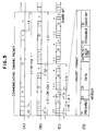
- Sections (a) and (b) of Fig. 5 show a bit construction and explain in detail the division of the packet of the communication channel frame of sections (a) and (b) of Fig. 4.
- the packet of the communication channel frame can be divided with no problems.
- Fig. 5(d) shows a typical construction of the packet constituted by a preamble for the synchronization of the carrier frequency and bit timing and error correcting numerals, a header showing calling and answering communicating units, and a postamble for packet check numerals for detecting errors of numerals in transmitted and received data and error correcting numerals.
- Fig. 6 shows an example of the allocation of the carrier frequency prepared in advance with respect to the multiple transmission rate packet.
- the carrier frequencies f(l + 4i) of Fig. 6(b) are allocated, the carrier frequencies f(l + 3i) and f(l + 5i) of Fig. 6(a) are not used.
- the carrier frequencies f(3 + 8i) of Fig. 6(c) are allocated, the carrier frequencies f(3 + 6i) and f(3 + 10i) of Fig. 6(b), and the carrier frequencies f(3 + 5i), f(3 + 7i), f(3 + 9i) and f(3 + 11i) of Fig. 6(a) are not used.
- Fig. 7 shows an example of the construction of each of the user's communication units used in the satellite communication system in Fig. 3A.
- a transmitter is constructed by a transmitting control section 51, a coding section 52, a modulating section 53, an intermediate frequency transmitting section 54 and a radio frequency transmitting section 55.
- a high frequency signal is transmitted from an antenna 57 through a diplexer 56 to a satellite.
- a high frequency signal from the satellite is received by the antenna 57 and is supplied as receiving data by a receiver through the diplexer 56.
- the receiver is constituted by a radio frequency receiving section 58, an intermediate frequency receiving section 59, a demodulating section 60, a decoding section 61, and a receiving control section 62.
- the modulating and demodulating sections and the coding and decoding sections shown by a broken line of Fig. 7 may be of a known digital type in which the speed is changed by an external control.
- Information required to call is outputted from the transmitting control section 51 in accordance with the construction of the common signalling channel at a predetermined transmission rate, and the calling signal is set to be at an intermediate carrier frequency for the common signalling channel by the intermediate frequency transmitting section 54, and is then transmitted.
- the transmission parameters of the communication channel allocated by the line control unit LCU are read and memorized by the receiving control section 62 through the intermediate frequency receiving section 59 set at the intermediate carrier frequency for the common signalling channel.
- the allocated transmission rate, packet length and packet position within the broken line of Fig. 7 are set at the intermediate carrier frequency for the communicating channel allocated by the intermediate frequency transmitting and receiving sections 54 and 59.
- the modulating and demodulating sections 53 and 60 have a known analog filter for changing the band by an external control, and the transmitting signal bandwidth and the receiving signal bandwidth are set in accordance with the allocated transmission rate.
- the receiving noise band of mode 2 of Fig. 4(b) is half that of mode 3 of Fig. 4(c), thereby improving the receiving channel quality by 3dB.
- mode 1 of Fig. 4(a) can be improved by 3dB in receiving channel quality in comparison with mode 2 of Fig. 4(b).
- Fig. 8 shows another embodiment of the present invention in which frequency source is effectively utilized.
- the transmission parameters during the talking communication as in Fig. 8 can easily be reset by using the common signalling channel instead of two carrier frequencies if the common signalling channel and the communication channel are constructed as shown in Fig. 9.
- a time frame is composed of times T1 and T2, and all the user's communicating units are switched to the carrier frequency F(0) during time T1 to transmit and receive the common signalling channel.
- the line control unit LCU gives instructions for changing the packet position to the user's communication units A, C, D, and F after a fixed time frame using the common signalling channel having time T1.
- the user's communication units A, C, D, and F memorize these instructions in the receiving control section 62 of Fig. 7, and operate a counter and change to transmitting and receiving packet positions after the fixed time frame.
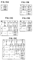
- Fig. 10 to 13 are views for explaining a packet divisional method which can be prepared in advance, in the case of transmitting bandwidth 4Fw for example, and a plurality of simultaneously communicable forms in this packet division and the receiving channel quality or receiving bandwidth of the communicating channel.
- the packet division of the transmitting bandwidth 4Fw and the communicating channel is performed by forming 4, 8 and 16 packets with the packets [1] to [16] of Fig. 10 adjacent to each other.
- Fig. 11 shows such a divisional method
- Fig. 12 shows the relation between the receiving bandwidths of packets obtained by the division of Fig. 11 and the information transmitting units P, 2P and 4P which can be used in user's communication units for treating only one carrier frequency.
- Fig. 13A to 13E show the receiving bandwidth of the packets and the information transmitting units corresponding to the individual division and a plurality of simultaneously communicable forms which can be received in the system.
- the communication forms are limited to 1 : 1 in the case of the numbers of packets 8, 4, 2, 1 obtained by the frequency division although this form has the best receiving channel quality.
- the numbers of packets 12, 7, 3 by the time division can correspond to various kinds of communication forms although the receiving channel quality is worse than that of the former form obtained by the frequency division.
- the transmission parameters of the communication channel including at least transmission rate, packet length and packet position are selected from a plurality of transmission parameters prepared in advance and are set through the common signalling channel, thereby freely corresponding to various kinds of communicating forms, various kinds of transmission rates corresponding to multi-media; various kinds of line situations such as attenuation due to rain-fall with a minimum multiplicity.
- the transmission parameters can be constructed to include a coding structure for error correction, etc., as well as the transmission rate, packet length and packet position.
- a certain error correcting coded numeral having a high gain therefor is often used to improve the channel quality, and make an antenna compact and economical in the satellite communication.
- the coding rate is set and changed at a fixed transmission rate, the information amount which can be transmitted per one packet can be changed.
- bit K I/ ⁇ where I is an information amount, and is received in a time slot length of a time interval S and is then transmitted, the information rate is K/S (b/s).
- Table 1 shows the results of the calculation of transmittable information amounts I and J in which bit K is designated in the longitudinal direction, and the coding rates ⁇ and ⁇ are designated in the transversal direction.
- the information rate is the same with respect to a first case in which an information amount 256 kb/s is transmitted at coding rate 1/2, and a second case in which an information amount 384 kb/s is transmitted at a coding rate 3/4.
- a conference using television for example can be held at a speed of 384 kb/s by the international standard using a packet which can transmit information amount 256 kb/s at coding rate 1 / 2.
- the television conference can be held at a speed of 384 kb/s and simultaneously a still picture often required in the conference can be transmitted at a speed of 64 kb/s as shown in item 1 of Table 1.
- the packet transmitting the information amount at a transmission rate of 192 kb/s and a coding rate of 1/2 is used in accordance with item 7 of Table 1, the information can be transmitted at the ISDN basic access speed of 144 kb/s by changing the coding rate to 3/4.
- a punctured system based on a certain decoder normally at coding rate 1/2 is often used to decode error correction at the coding rate greater than 2/3.
- the system has a greatly improved convenience for the users by setting and changing the coding rate using the common signalling channel and the packet header of the communication channel shown in Fig. 6. Further, in this case, the information rate is not changed so that there are no effects on the other communicating channels. Accordingly, even when all the information rates are used in Table 1, the basic speeds can be united as two speed systems of 32 kb/s and 48 kb/s.
Landscapes
- Engineering & Computer Science (AREA)
- Computer Networks & Wireless Communication (AREA)
- Signal Processing (AREA)
- Time-Division Multiplex Systems (AREA)
Claims (7)
- Mehrfachzugriffs-Kommunikationssystem zur Durchführung der Kommunikation zwischen mehreren Kommunikationseinheiten (3; A-N) unter Verwendung mehrerer Kommunikationskanäle und eines gemeinsamen Signalkanals zum Einrichten und Freigeben der Kommunikationskanäle, wobei
zumindest eine Signalkanalträgerfrequenz (FO) dem gemeinsamen Signalkanal zugeordnet ist; und
Kommunikationskanalträgerfrequenzen (F1-Fn), die sich von der Signalkanalträgerfrequenz (FO) unterscheiden, den Kommunikationskanälen zugeordnet werden;
gekennzeichnet durch einen Zeitblock, der aus einem ersten (T1) und zweiten (T2) Zeitschlitz für den gemeinsamen Signalkanal bzw. die Kommunikationskanäle besteht;
so daß der erste Zeitschlitz (T1) nur dem gemeinsamen Signalkanal zugeordnet ist, und der zweite Zeitschlitz (T2) zumindest den Kommunikationskanälen zugeordnet ist. - Mehrfachzugriffs-Kommunikationssystem nach Anspruch 1, bei welchem der zweite Zeitschlitz (T2) in mehrere Zeitabschnitte (t1, t2, ...) unterteilt ist, um zwischen einer Kommunikationseinheit (zum Beispiel A) und einer anderen Kommunikationseinheit (zum Beispiel X) zu kommunizieren.
- Mehrfachzugriffs-Kommunikationssystem nach Anspruch 1, bei welchem der dem gemeinsamen Signalkanal zugeordnete erste Zeitschlitz (T1) erstens zur Einrichtung eines neuen Kommunikationskanals in bezug auf eine Kommunikationseinheit verwendet wird, für welche ein Kommunikationskanal bereits eingerichtet wurde.
- Mehrfachzugriffs-Kommunikationssystem nach Anspruch 1, bei welchem der zweite Zeitschlitz (T2) ebenfalls dem gemeinsamen Signalkanal zugeordnet ist, um erstens den Kommunikationskanal freizugeben und zweitens die Trägerfrequenz des gemeinsamen Signalkanals zu übertragen, so daß die Trägerfrequenz (F1, ..., Fn) des Kommunikationskanals und die Trägerfrequenz (F0) des gemeinsamen Signalkanals nicht gleichzeitig übertragen werden.
- Mehrfachzugriffs-Kommunikationssystem nach Anspruch 1, bei welchem der zweite Zeitschlitz (T2) ebenfalls dem gemeinsamen Signalkanal zugeordnet ist, und zur Einrichtung eines Kommunikationskanals verwendet wird, der sich auf eine Kommunikationseinheit bezieht, für welche noch kein Kommunikationskanal eingerichtet wurde.
- Mehrfachzugriffs-Kommunikationssystem nach Anspruch 1, bei welchem zumindest entweder der erste oder der zweite Zeitschlitz (T1, T2), der dem gemeinsamen Signalkanal zugeordnet ist, in mehrere Zeitabschnitte unterteilt ist, um mehrere gemeinsame Signalkanäle zu empfangen.
- Mehrfachzugriffs-Kommunikationssystem nach Anspruch 1, welches mehrere Trägerfrequenzen aufweist, die dem gemeinsamen Signalkanal zugeordnet sind.
Applications Claiming Priority (4)
| Application Number | Priority Date | Filing Date | Title |
|---|---|---|---|
| JP53014/87 | 1987-03-10 | ||
| JP62053014A JP2597568B2 (ja) | 1987-03-10 | 1987-03-10 | 多元接続通信方式 |
| JP240839/87 | 1987-09-28 | ||
| JP62240839A JP2685760B2 (ja) | 1987-09-28 | 1987-09-28 | 多元接続選択通信方式 |
Publications (3)
| Publication Number | Publication Date |
|---|---|
| EP0282028A2 EP0282028A2 (de) | 1988-09-14 |
| EP0282028A3 EP0282028A3 (en) | 1990-11-14 |
| EP0282028B1 true EP0282028B1 (de) | 1994-12-14 |
Family
ID=26393715
Family Applications (1)
| Application Number | Title | Priority Date | Filing Date |
|---|---|---|---|
| EP88103712A Expired - Lifetime EP0282028B1 (de) | 1987-03-10 | 1988-03-09 | Übertragungssystem mit Vielfachzugriff |
Country Status (3)
| Country | Link |
|---|---|
| US (1) | US4868811A (de) |
| EP (1) | EP0282028B1 (de) |
| DE (1) | DE3852410T2 (de) |
Families Citing this family (45)
| Publication number | Priority date | Publication date | Assignee | Title |
|---|---|---|---|---|
| GB2229064B (en) * | 1987-06-11 | 1990-12-12 | Software Sciences Limited | An area communications system |
| US5229995A (en) * | 1990-07-17 | 1993-07-20 | Northern Telecom Limited | Radio link architecture for wireless communication systems |
| US5134615A (en) * | 1990-10-05 | 1992-07-28 | Motorola, Inc. | Frequency agile tdma communications system |
| WO1992007434A1 (en) * | 1990-10-23 | 1992-04-30 | Omnipoint Corporation | Method and apparatus for establishing spread spectrum communications |
| US5307348A (en) * | 1990-11-05 | 1994-04-26 | Motorola, Inc. | Scheduling in a communication system |
| US5303393A (en) * | 1990-11-06 | 1994-04-12 | Radio Satellite Corporation | Integrated radio satellite response system and method |
| US5455823A (en) * | 1990-11-06 | 1995-10-03 | Radio Satellite Corporation | Integrated communications terminal |
| US5983112A (en) * | 1990-12-06 | 1999-11-09 | Hughes Electronics Corporation | Frequency, time and power level diversity system for digital radio telephony |
| US6847611B1 (en) | 1990-12-10 | 2005-01-25 | At&T Corp. | Traffic management for frame relay switched data service |
| US5359595A (en) * | 1991-01-09 | 1994-10-25 | Rockwell International Corporation | Skywave adaptable network transceiver apparatus and method using a stable probe and traffic protocol |
| FR2672171B1 (fr) * | 1991-01-24 | 1993-04-09 | Alcatel Nv | Procede et reseau de communication a allocation de frequences. |
| US5517492A (en) * | 1992-01-17 | 1996-05-14 | Motorola, Inc. | Increased speech interleave with reduced delay |
| US5689245A (en) * | 1992-10-19 | 1997-11-18 | Radio Satellite Corporation | Integrated communications terminal |
| US5434850A (en) | 1993-06-17 | 1995-07-18 | Skydata Corporation | Frame relay protocol-based multiplex switching scheme for satellite |
| US6771617B1 (en) | 1993-06-17 | 2004-08-03 | Gilat Satellite Networks, Ltd. | Frame relay protocol-based multiplex switching scheme for satellite mesh network |
| US5469431A (en) * | 1993-07-12 | 1995-11-21 | Philips Electronics North America Corp. | Method of and apparatus for channel mapping with relative service identification |
| US6018528A (en) * | 1994-04-28 | 2000-01-25 | At&T Corp | System and method for optimizing spectral efficiency using time-frequency-code slicing |
| US5542115A (en) | 1994-06-24 | 1996-07-30 | Pioneer Tech Development Limited | Paging method and apparatus |
| US6282683B1 (en) * | 1994-09-26 | 2001-08-28 | Adc Telecommunications, Inc. | Communication system with multicarrier telephony transport |
| US6334219B1 (en) | 1994-09-26 | 2001-12-25 | Adc Telecommunications Inc. | Channel selection for a hybrid fiber coax network |
| JP3511408B2 (ja) * | 1994-10-06 | 2004-03-29 | パイオニア株式会社 | Catv電話システムの端末器及びセンタ装置 |
| USRE42236E1 (en) | 1995-02-06 | 2011-03-22 | Adc Telecommunications, Inc. | Multiuse subcarriers in multipoint-to-point communication using orthogonal frequency division multiplexing |
| US7280564B1 (en) | 1995-02-06 | 2007-10-09 | Adc Telecommunications, Inc. | Synchronization techniques in multipoint-to-point communication using orthgonal frequency division multiplexing |
| FI98675B (fi) * | 1995-02-17 | 1997-04-15 | Nokia Telecommunications Oy | Aikavälien allokoiminen matkaviestinjärjestelmässä |
| US5719868A (en) * | 1995-10-05 | 1998-02-17 | Rockwell International | Dynamic distributed, multi-channel time division multiple access slot assignment method for a network of nodes |
| US6219840B1 (en) * | 1996-03-29 | 2001-04-17 | Motorola, Inc. | Method for assigning communication resources in a communication system |
| US5959999A (en) * | 1996-09-20 | 1999-09-28 | Linkabit Wireless, Inc. | Providing control-function data in communication-data channel of a full-mesh satellite communication network by dynamic time-slot assignment in TDMA-frame communication channel |
| US5841765A (en) * | 1996-10-10 | 1998-11-24 | Skydata, Inc. | Demand-based connection management integrated services access terminal (ISAT) for satellite communication system |
| JP3276572B2 (ja) * | 1996-12-20 | 2002-04-22 | 富士通株式会社 | ディジタル多重無線装置 |
| US6373858B1 (en) * | 1997-04-21 | 2002-04-16 | Hughes Electronics Corporation | Burst format and associated signal processing to improve frequency and timing estimation for random access channels |
| US6157627A (en) * | 1997-06-23 | 2000-12-05 | Telefonaktiebolaget Lm Ericsson | Channel allocation for mixed multislot services |
| US6081524A (en) | 1997-07-03 | 2000-06-27 | At&T Corp. | Frame relay switched data service |
| DE69834492T2 (de) * | 1997-07-15 | 2007-05-10 | Viasat Inc., Carlsbad | Verfahren und vorrichtung zur segmentierung, wiederaufbau und inversem multiplexing von paketen und atm zellen über satelliten/drahtlose netzwerke |
| US7570645B2 (en) | 2000-01-18 | 2009-08-04 | Viasat, Inc. | Frame format and frame assembling/disassembling method for the frame format |
| US6226279B1 (en) | 1997-10-22 | 2001-05-01 | Telefonaktiebolaget L M Ericsson (Publ) | Allowing several multiple access schemes for packet data in a digital cellular communication system |
| US6996088B1 (en) * | 1998-09-18 | 2006-02-07 | Harris Corporation | Distributed trunking mechanism for VHF networking |
| DE19855194C2 (de) * | 1998-11-30 | 2001-06-13 | Siemens Ag | Verfahren und Kommunikationssystem zur Übertragung von Daten einer Kombination mehrerer Dienste über gemeinsam genutzte physikalische Kanäle |
| JP3586417B2 (ja) * | 2000-07-14 | 2004-11-10 | 三菱電機株式会社 | 衛星通信システム並びにこの衛星通信システムに用いられる子地球局及び親地球局 |
| DE10125909A1 (de) * | 2001-05-28 | 2002-12-12 | Infineon Technologies Ag | Datenübertragungssystem mit hoher Datenübertragungsrate |
| US7110421B2 (en) * | 2001-11-28 | 2006-09-19 | Sony Corporation | System and method for transmitting information over multiple channels |
| GB2384394A (en) * | 2002-01-18 | 2003-07-23 | Inmarsat Ltd | Adapting transmission parameters to link conditions |
| US7277411B2 (en) * | 2002-08-21 | 2007-10-02 | D.S.P. Group Ltd. | Method and system for transmitting and receiving data in a TDMA frequency hopping system utilizing frequency diversity |
| US10355825B2 (en) * | 2004-07-21 | 2019-07-16 | Qualcomm Incorporated | Shared signaling channel for a communication system |
| US7715319B2 (en) | 2007-02-06 | 2010-05-11 | Viasat, Inc. | Default assignment of scheduled transmissions |
| US11070523B2 (en) | 2017-04-26 | 2021-07-20 | National University Of Kaohsiung | Digital data transmission system, device and method with an identity-masking mechanism |
Family Cites Families (3)
| Publication number | Priority date | Publication date | Assignee | Title |
|---|---|---|---|---|
| US4339816A (en) * | 1980-05-29 | 1982-07-13 | International Telephone And Telegraph Corporation | Conferencing apparatus and methods for a frequency division multiplex communications system |
| US4590595A (en) * | 1983-03-28 | 1986-05-20 | Yo Morimura | Apparatus for detecting in-band single frequency signaling tones from FDM channels |
| CA1262382A (en) * | 1984-05-10 | 1989-10-17 | Nec Corporation | Station relief arrangement for use in relieving operation of a reference station in a tdma network without reduction of frame availability |
-
1988
- 1988-02-29 US US07/161,761 patent/US4868811A/en not_active Expired - Lifetime
- 1988-03-09 EP EP88103712A patent/EP0282028B1/de not_active Expired - Lifetime
- 1988-03-09 DE DE3852410T patent/DE3852410T2/de not_active Expired - Fee Related
Also Published As
| Publication number | Publication date |
|---|---|
| DE3852410T2 (de) | 1995-05-24 |
| EP0282028A3 (en) | 1990-11-14 |
| DE3852410D1 (de) | 1995-01-26 |
| US4868811A (en) | 1989-09-19 |
| EP0282028A2 (de) | 1988-09-14 |
Similar Documents
| Publication | Publication Date | Title |
|---|---|---|
| US4868811A (en) | Multiple access communication system | |
| US5351240A (en) | Communication link having dynamically allocatable auxiliary channel for data bursts | |
| JP3477492B2 (ja) | 時分割多重接続(tdma)トランクド・システム用のチャネル再割当方法 | |
| US5420851A (en) | Method of multiple access | |
| JP4420561B2 (ja) | 無線チャネルを有する家庭用通信システムにおける伝送方法 | |
| US5848070A (en) | Multiframe structure and handling protocol for a telecommunication network | |
| US5570355A (en) | Method and apparatus enabling synchronous transfer mode and packet mode access for multiple services on a broadband communication network | |
| US5959999A (en) | Providing control-function data in communication-data channel of a full-mesh satellite communication network by dynamic time-slot assignment in TDMA-frame communication channel | |
| US5889765A (en) | Bi-directional communications network | |
| US6424645B1 (en) | TDMA radio communication system achieving simultaneous assignment of channels to multiple terminal stations | |
| EP0951154A2 (de) | Verfahren und Vorrichtung zum Ermöglichen eines Mehrfachzugriffs in einem Breitband-Kommunikationsnetzwerk | |
| EP0827308A2 (de) | Gemeinsamer Kommunikationskanal | |
| US4586177A (en) | Integrated narrowband and wideband TDMA networks | |
| WO1993015573A1 (en) | Cdma/tdma communication system | |
| KR19990022492A (ko) | 광대역 통신 시스템의 역경로 할당 및 경합 해소 기구 | |
| HUT65532A (en) | Method for multipurpose utilizing signal sources in communication systems | |
| EP0845917B1 (de) | Durchführung von verzögerungskritischen Diensten in einem Kabel-Fernseh-System | |
| JP3058270B2 (ja) | Cdma通信方法、スペクトラム拡散通信システム、基地局、および端末装置 | |
| US7408892B2 (en) | Upstream adaptive modulation in DOCSIS based applications | |
| JP2002532987A (ja) | 無線通信システムにおけるデータ伝送方法 | |
| US6351469B1 (en) | Sound/data sharing communications system | |
| KR100392285B1 (ko) | 전기통신망과그전기통신망에사용하기위한2차국및1차국,통신방법 | |
| JP3433859B2 (ja) | ローカルアクセスケーブル上のマルチメディア通信用の制御 | |
| JP2002505817A (ja) | 共通のデータ媒体でデータ伝送するための方法 | |
| JP2685760B2 (ja) | 多元接続選択通信方式 |
Legal Events
| Date | Code | Title | Description |
|---|---|---|---|
| PUAI | Public reference made under article 153(3) epc to a published international application that has entered the european phase |
Free format text: ORIGINAL CODE: 0009012 |
|
| AK | Designated contracting states |
Kind code of ref document: A2 Designated state(s): DE FR GB |
|
| PUAL | Search report despatched |
Free format text: ORIGINAL CODE: 0009013 |
|
| AK | Designated contracting states |
Kind code of ref document: A3 Designated state(s): DE FR GB |
|
| 17P | Request for examination filed |
Effective date: 19910326 |
|
| 17Q | First examination report despatched |
Effective date: 19930317 |
|
| GRAA | (expected) grant |
Free format text: ORIGINAL CODE: 0009210 |
|
| AK | Designated contracting states |
Kind code of ref document: B1 Designated state(s): DE FR GB |
|
| PG25 | Lapsed in a contracting state [announced via postgrant information from national office to epo] |
Ref country code: FR Effective date: 19941214 |
|
| REF | Corresponds to: |
Ref document number: 3852410 Country of ref document: DE Date of ref document: 19950126 |
|
| EN | Fr: translation not filed | ||
| PLBE | No opposition filed within time limit |
Free format text: ORIGINAL CODE: 0009261 |
|
| STAA | Information on the status of an ep patent application or granted ep patent |
Free format text: STATUS: NO OPPOSITION FILED WITHIN TIME LIMIT |
|
| 26N | No opposition filed | ||
| REG | Reference to a national code |
Ref country code: GB Ref legal event code: 746 Effective date: 19981008 |
|
| REG | Reference to a national code |
Ref country code: GB Ref legal event code: IF02 |
|
| PGFP | Annual fee paid to national office [announced via postgrant information from national office to epo] |
Ref country code: DE Payment date: 20060302 Year of fee payment: 19 |
|
| PGFP | Annual fee paid to national office [announced via postgrant information from national office to epo] |
Ref country code: GB Payment date: 20060308 Year of fee payment: 19 |
|
| GBPC | Gb: european patent ceased through non-payment of renewal fee |
Effective date: 20070309 |
|
| PG25 | Lapsed in a contracting state [announced via postgrant information from national office to epo] |
Ref country code: DE Free format text: LAPSE BECAUSE OF NON-PAYMENT OF DUE FEES Effective date: 20071002 |
|
| PG25 | Lapsed in a contracting state [announced via postgrant information from national office to epo] |
Ref country code: GB Free format text: LAPSE BECAUSE OF NON-PAYMENT OF DUE FEES Effective date: 20070309 |