EP0282030B1 - Stérilisateur chauffant par micro-ondes - Google Patents
Stérilisateur chauffant par micro-ondes Download PDFInfo
- Publication number
- EP0282030B1 EP0282030B1 EP88103716A EP88103716A EP0282030B1 EP 0282030 B1 EP0282030 B1 EP 0282030B1 EP 88103716 A EP88103716 A EP 88103716A EP 88103716 A EP88103716 A EP 88103716A EP 0282030 B1 EP0282030 B1 EP 0282030B1
- Authority
- EP
- European Patent Office
- Prior art keywords
- attachment
- turning
- microwave heating
- retainer
- over
- Prior art date
- Legal status (The legal status is an assumption and is not a legal conclusion. Google has not performed a legal analysis and makes no representation as to the accuracy of the status listed.)
- Expired
Links
Images


Classifications
-
- H—ELECTRICITY
- H05—ELECTRIC TECHNIQUES NOT OTHERWISE PROVIDED FOR
- H05B—ELECTRIC HEATING; ELECTRIC LIGHT SOURCES NOT OTHERWISE PROVIDED FOR; CIRCUIT ARRANGEMENTS FOR ELECTRIC LIGHT SOURCES, IN GENERAL
- H05B6/00—Heating by electric, magnetic or electromagnetic fields
- H05B6/64—Heating using microwaves
- H05B6/78—Arrangements for continuous movement of material
- H05B6/782—Arrangements for continuous movement of material wherein the material moved is food
-
- A—HUMAN NECESSITIES
- A23—FOODS OR FOODSTUFFS; TREATMENT THEREOF, NOT COVERED BY OTHER CLASSES
- A23B—PRESERVATION OF FOODS, FOODSTUFFS OR NON-ALCOHOLIC BEVERAGES; CHEMICAL RIPENING OF FRUIT OR VEGETABLES
- A23B2/00—Preservation of foods or foodstuffs, in general
- A23B2/05—Preservation of foods or foodstuffs, in general by heating using irradiation or electric treatment
- A23B2/08—Preservation of foods or foodstuffs, in general by heating using irradiation or electric treatment using microwaves or dielectric heating
-
- Y—GENERAL TAGGING OF NEW TECHNOLOGICAL DEVELOPMENTS; GENERAL TAGGING OF CROSS-SECTIONAL TECHNOLOGIES SPANNING OVER SEVERAL SECTIONS OF THE IPC; TECHNICAL SUBJECTS COVERED BY FORMER USPC CROSS-REFERENCE ART COLLECTIONS [XRACs] AND DIGESTS
- Y10—TECHNICAL SUBJECTS COVERED BY FORMER USPC
- Y10S—TECHNICAL SUBJECTS COVERED BY FORMER USPC CROSS-REFERENCE ART COLLECTIONS [XRACs] AND DIGESTS
- Y10S99/00—Foods and beverages: apparatus
- Y10S99/14—Induction heating
Definitions
- This invention relates to a microwave sterilizer used for the sterilizing treatment of sealed foodstuffs may means of microwave irradiation.
- a sterilizer for sterilizing sealed foodstuffs by means of microwave as described above, a sterilizer having such construction that a foodstuff (hereinafter referred to as “material to be sterilized") which has been packed and sealed is contained in a pressure container (hereinafter referred to simply as "retainer") made from a material permeable to microwave, and the retainer as described above is placed in a cavity and irradiated with microwave, whereby the material to be sterilized in the retainer can be sterilized has been proposed as disclosed in Japanese Patent Publication No. 26949/1983, and such sterilizer has been put to practical use.
- USP 3,261,140 and USP 3,335,253 disclose an apparatus for heating or sterilizing sealed foodstuffs by irradiating them with microwave while transferring continuously said sealed foodstuffs.
- the present invention has been made in view of the above, and an object of the present invention is to provide a microwave heating sterilizer by which "materials to be sterilized" can be homogeneously and continuously heated.
- this object of the present invention is to provide a microwave sterilizer by which sterilization can be effected for a short period of time which is a characteristic feature of microwave irradiating sterilization, and temperature differences in respective parts are made minimum at the time when microwave irradiation (sterilization) is completed with respect to "materials to be sterilized" in a package as a matter of course, differences in temperature rise in the respective parts in the course of sterilization are also made minimum.
- the present invention concerns a microwave heating sterilizer wherein a package which is prepared by charging a tray or pouch made of a material permeable to microwave with a foodstuff being a substance to be sterilized and sealing the tray or pouch thus charged is irradiated with microwave while conveying continuously the same, characterized in that said package is first irradiated with microwave by means of a waveguide, then the package is turned over and irradiated with microwave.
- the present invention relates to a sterilizer wherein a retainer made from a material being permeable to microwave and heat-resistant and which contains a "material to be sterilized” is conveyed in and passed through a cavity being irradiated with microwave through a waveguide, comprising such construction that said retainer is made possible to be turned over in the course of the conveyance thereof.
- the construction involves supporting shafts extending from the positions determined at point symmetry with respect to the center of said retainer on the opposite end portions thereof, and turning-over parts each having a higher slide surface than the other part during conveyance of said retainer and a turning-over groove.
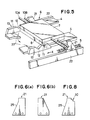
- the microwave heating sterilizer according to the present invention is of a construction shown schematically in Fig. 1 wherein reference numeral 1 designates a cavity, and 2 designates a waveguide emitting downwardly microwave into the cavity 1.
- reference numeral 1 designates a cavity
- 2 designates a waveguide emitting downwardly microwave into the cavity 1.
- conveying parts 20 and 20 for continuously transferring a retainer which will be described hereinbelow along the horizontal direction X are disposed on the lower opposite sides thereof.
- the conveying part 20 is composed of a guide rail 4 and a driving chain 5 extending along the inside of the guide rail 4.
- the driving chain 5 is made of polyacetal or the like which does not leak microwave.
- the retainer 6 is composed of two plate-like members 7 and 8 each of which is made from a material being permeable to microwave and heat-resistant such as silicon, glass fiber filled silicon, ceramics or the like.
- the retainer 6 contains a "material to be sterilized" A being a sealed foodstuff in a containing part 9 formed by joining these two plate-like members 7 and 8.
- Supporting shafts 10A and 10A as well as 10B and 10B extend from positions determined at point symmetry with respect to the center of the retainer 6 on the opposite end surfaces thereof.
- the guide rail 4 is positioned outside the retainer main body at a turning round position and is provided with a turning-over part 13 the opposite sides thereof being inclined and having a higher slide surface 11 and a turning-over groove 12.
- the conveying part 20 has such a construction that attachments 21 abutting upon a supporting shaft of the retainer 6 are attached to the driving chain 5 with a given interval.
- the attachment 21 is conveyed along an attachment guide 22 for restricting the conveying direction in the case when said attachment 21 is conveyed by means of the driving chain 5.
- a position of the turning-over part 13 in the guide rail 4 is lower than the other part thereof.
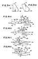
- the attachment 21 is rotatably attached to the driving chain 5, and as shown in Fig. 3(a) or (b), either a notched portion 24 is defined on the lower part of the abutting surface on the abutting side of the attachment 21, or an inclined portion 25 is formed on said lower part of the abutting surface, whereby said notched portion 24 or said inclined portion 25 pushes only either of supporting shafts 10A and 10B of the retainer 6 during turning-over operation, whilst said portion 24 or 25 does not abut upon the other supporting shaft.
- the attachment 21 has further another notch 26 having substantially the same angle as that of the turning-over groove 12 on the conveying side on the lower part of the back thereof.
- first of all horizontal conveyance is effected in such that the retainer 6 is positioned over the guide rail 4, and the attachment 21 abuts against the lower supporting shaft 10B.
- the retainer 6 does not abut upon the slide surface 11, but the supporting shaft 10B abuts upon said slide surface, so that the supporting shaft 10A positions ahead of the supporting shaft 10B and the retainer 6 descends.
- the retainer 6 is turned over in such that the supporting shaft 10B becomes ahead of the supporting shaft 10A as a result of shift of the center of gravity of the retainer 6 while leaving the attachment 21 to push the supporting shaft 10B.
- the attachment 21 is positioned on the lower portion of the attachment guide 22 as shown in Fig. 4(d) and pushes the retainer 6 up along the profile of the turning-over groove 12 to be in a complete turned over state.
- an angle of the front surface of the attachment 21 is substantially 90° with respect to an inclined surface 12A defining the trunign-over groove 12 of the turning-over part 13.
- the construction of the attachment 21 is made to have a notch 26 with an angle of substantially 90° which is defined by an inclined surface 12B of the turning-over groove 12 and the inclined side 25 in the front of the attachment 21, more specifically, when the angles of the inclined surfaces 12A and 12B are made to be 60° and 30°, respectively, a turning-over operation in the turning-over groove and conveyance from the turning-over groove become to be smoothly possible so that it is very efficient in the case where angles of the inclined sides 25 and 26 of the attachment are 15° and 45°, respectively. Furthermore, when an upper guide rail 4B is disposed over the guide rail 4 other than said turning-over part 13, its turning-over operation can be smoothly carried out.
- no lower portion may be defined at the position of the turning-over part 13 of the attachment guide 22 as shown in Fig. 5 in order to continuously transfer the attachment 21 in horizontal direction.
- a receiving part 27 which extends downwards and obliquely in front of the turning-over part 13 of the guide rail 4 may be provided. In this case, when the attachment 21 is fixed to the chain at two points, it can prevent that the attachment 21 rotates around its stationary shaft as the center during revolution of the attachment 21 along the chain, so that it is efficient.
- the turning-over mechanism of the present sterilizer is shown in Figs. 7(a) - (e).
- the retainer 6 positions on the guide rail 4 in the case where the retainer 6 is horizontally conveyed on the slide surface 11 at the turning-over part 13 as shown in Fig. 7(a), and the attachment 21 abuts upon the lower supporting shaft 10B on the slide surface 11, whereby the conveyance is effected.
- the supporting shaft 10A is ahead of the supporting shaft 10B and the retainer 6 descends at the position where the supporting shaft 10A is conveyed to the turning-over groove 12 of the turning-over part 13, so that the retainer 6 rotates forwardly in the turning-over groove 12, and there is a state where the attachment 21 is distant from the supporting shaft 10B as shown in Fig. 7(c).
- the front end of the retainer 6 rotated about against the receiving part 27 to keep a turned over state, and at the same time a condition where the supporting a shifts 10A and 10B are in contact with the inclined surface of the turning-over groove 12, respectively, is attained as shown in fig. 7(d).
- Fig. 7(e) the retainer 6 is pushed up along the profile of the turning-over groove 12 by means of the inclined surface 25 of the attachment 21, and the retainer 6 is conveyed while maintaining the turned over state thereof as shown in Fig. 7(f).
- the profile of the attachment 21 may be the one shown in Fig.
- a sealed foodstuff in the retainer is irradiated with microwave to sterilize the foodstuff while repeating the above-mentioned operations in its cavity with a required number of times.
- a stepped notch 30 on the rear upper portion of the attachment 21 on the side opposite to the abutting surface thereof as shown in Fig. 8.
- the retainer according to the present invention is composed of two plate-like members 7 and 8 each of which is made from a material being permeable to microwave and heat-resistant such as silicon, glass fiber filled Teflon, ceramics or the like as shown in Fig. 9.
- the retainer contains a "material to be sterilized" A being a sealed foodstuff in a containing part 9 formed by joining these two plate-like members 7 and 8, and the sterilization is effected while remaining the "material to be sterilized" A contained in the containing part 9.
- Columnar supporting shafts 10A and 10A as well as 10B and 10B extend from positions determined at point symmetry with respect to the center of the retainer on the opposite end surfaces thereof.
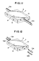
- These supporting shafts may be not columnar, but plate-like supporting shafts 10A and 10A as well as 10B and 10B each end portion of which may be formed into a circular arc as shown in Fig. 10. Furthermore, such supporting shaft 10A and 10A having point symmetrical profile may be disposed on only either of the plate-like members 7 and 8 as shown in Fig. 11.
- these supporting shafts may be ether integrally formed on the plate-like members by means of injection molding or the like manner, or the supporting shafts 10A, 10A, 10B and 10B may be separately fabricated and they may be joined to the plate-like members by means of threaded engagement or the like manner.
- the retainer is irradiated with microwave to sterilize the sealed foodstuff in its cavity of the above-mentioned heating sterilizer while turning over the retainer with a required number of times.
- a profile of the turning-over groove is defined in V-shape, and the inclined surface of the turning-over groove is arranged so as to form substantially 90° angle with respect to the inclined side in the front of the attachment, the retainer can be more smoothly turned round in the turning-over groove, and the retainer can also be smoothly conveyed from the turning-over groove.
- the present invention provides a microwave heating sterilizer provided with a mechanism for turning over a retainer made from a material being permeable to microwave and which contains a "material to be sterilized" in a cavity irradiated with microwave therein supporting shafts extend from positions determined at point symmetry with respect to the center of the retainer on the opposite ends thereof, and turning-over parts each having a higher slide surface than the other part thereof on the midway of a guide which conveys the retainer and a turning-over groove on the midpoint thereof are provided.
Landscapes
- Life Sciences & Earth Sciences (AREA)
- Engineering & Computer Science (AREA)
- Wood Science & Technology (AREA)
- Zoology (AREA)
- Chemical & Material Sciences (AREA)
- Food Science & Technology (AREA)
- Polymers & Plastics (AREA)
- Physics & Mathematics (AREA)
- Electromagnetism (AREA)
- Food Preservation Except Freezing, Refrigeration, And Drying (AREA)
- Apparatus For Disinfection Or Sterilisation (AREA)
Claims (16)
- Stérilisateur chauffant par micro-ondes dans lequel un logement (6) constitué par une matière perméable aux micro-ondes et réfactaire et contenant une matière à stériliser (A) est transporté et entraîné à travers une cavité (1) irradiée par micro-ondes par l'intermédiaire d'un guide d'ondes (2), caractérisé par
des arbres de support (10A, 10B) partant de positions déterminées en symétrie ponctuelle par rapport au centre du logement (6) sur ses portions terminales opposées,
des rails de guidage (4,13) du logement comportant chacune une partie de basculement (13) comportant une surface de glissement (11) et une rainure de basculement (12), et
des parties de transport (20) où un taquet (21), qui s'appuie sur lesdits arbres de support (10A,10B) pour transporter ledit dispositif de retenue (6) dans la direction de transport le long d'un guide de taquet (22), est fixé à une chaîne de transmission (5). - Stérilisateur chauffant par micro-ondes selon la revendication 1, dans lequel la partie à rainures de basculement dudit guide de taquet est abaissée, et ledit appendice est fixé de façon à pouvoir tourner.
- Stérilisateur chauffant par micro-ondes selon la revendication 1, dans lequel une partie réceptrice s'étendant obliquement vers le bas à l'avant de la partie de basculement du rail de guidage du logement est prévue.
- Stérilisateur chauffant par micro-ondes selon la revendication 2, dans lequel une partie réceptrice s' étendant obliquement vers le bas à l'avant de la partie de basculement du rail de guidage du logement est prévue.
- Stérilisateur chauffant par micro-ondes selon la revendication 2, dans lequel une encoche ayant une surface inclinée d'un angle sensiblement égal à celui du coté du transport de ladite rainure de basculement est définie sur la partie inférieure à l'arrière dudit taquet.
- Stérilisateur chauffant par micro-ondes selon la revendication 1, dans lequel ledit guide de taquet présente le même niveau sur toute sa surface, et ledit taquet n'est pas entraîné en rotation.
- Stérilisateur chauffant par micro-ondes sel on la revendication 6, dans lequel une partie réceptrice s'étendant obliquement vers le bas à l'avant de la partie de basculement du rail de guidage du logement est prévue.
- Stérilisateur chauffant par micro-ondes selon la revendication 3, dans lequel un angle de la surface inclinée d'un côté de poussée vers le haut de ladite rainure de basculement est rendu sensiblement égal à celui de ladite partie réceptrice.
- Stérilisateur chauffant par micro-ondes selon la revendication 4, dans lequel un angle de la surface inclinée d'un côté de poussée vers le haut de ladite rainure de basculement est rendu sensiblement égal à celui de ladite partie réceptrice.
- Stérilisateur chauffant par micro-ondes selon la revendication 7, dans lequel un angle de la surface inlinée d'un côté de poussée vers le haut de ladite rainure de basculement est rendu sensiblement égal à celui de ladite partie réceptrice.
- Stérilisateur chauffant par micro-ondes selon la revendication 2, dans lequel une portion à encoche est définie à la partie inférieure du côté d'appui dudit taquet.
- Stérilisateur chauffant par micro-ondes sel on la revendication 2, dans lequel une surface inclinée descendant vers l'intérieur est prévue à la partie inférieure du côté d'appui dudit taquet.
- Stérilisateur chauffant par micro-ondes selon la revendication 6, dans lequel une surface inclinée descendant vers l'extérieur est prévue à la partie inférieure du côté d'appui dudit taquet.
- Stérilisateur chauffant par micro-ondes selon la revendication 1, dans lequel une encoche étagée est définie à la partie supérieure à l'arrière dudit taquet.
- Stérilisateur chauffant par micro-ondes selon la revendication 2, dans lequel une encoche étagée est définie à la partie supérieure à l'arrière dudit taquet.
- Stérilisateur chauffant par micro-ondes selon la revendication 6, dans lequel une encoche étagée est définie à la partie supérieure à l'arrière dudit taquet.
Applications Claiming Priority (8)
| Application Number | Priority Date | Filing Date | Title |
|---|---|---|---|
| JP34758/87U | 1987-03-10 | ||
| JP3475887U JPH056785Y2 (fr) | 1987-03-10 | 1987-03-10 | |
| JP42336/87U | 1987-03-23 | ||
| JP4233587U JPH056786Y2 (fr) | 1987-03-23 | 1987-03-23 | |
| JP4233687U JPH0513196Y2 (fr) | 1987-03-23 | 1987-03-23 | |
| JP42335/87U | 1987-03-23 | ||
| JP15383087U JPH056788Y2 (fr) | 1987-10-07 | 1987-10-07 | |
| JP153830/87U | 1987-10-07 |
Publications (2)
| Publication Number | Publication Date |
|---|---|
| EP0282030A1 EP0282030A1 (fr) | 1988-09-14 |
| EP0282030B1 true EP0282030B1 (fr) | 1991-12-11 |
Family
ID=27459983
Family Applications (1)
| Application Number | Title | Priority Date | Filing Date |
|---|---|---|---|
| EP88103716A Expired EP0282030B1 (fr) | 1987-03-10 | 1988-03-09 | Stérilisateur chauffant par micro-ondes |
Country Status (6)
| Country | Link |
|---|---|
| US (1) | US4822967A (fr) |
| EP (1) | EP0282030B1 (fr) |
| AU (1) | AU605255B2 (fr) |
| CA (1) | CA1302680C (fr) |
| DE (1) | DE3866734D1 (fr) |
| DK (1) | DK125588A (fr) |
Families Citing this family (13)
| Publication number | Priority date | Publication date | Assignee | Title |
|---|---|---|---|---|
| FR2659518B1 (fr) * | 1990-03-07 | 1992-06-12 | Microondes Syst Sa | Dispositif applicateur d'ondes hyperfrequences pour le traitement de produits en feuille ou en nappe. |
| US5279788A (en) * | 1991-01-24 | 1994-01-18 | Eisai Co., Ltd. | Sterilizer for sealed container utilizing microwave |
| FR2704738B1 (fr) * | 1993-05-06 | 1997-08-08 | Moulinex Sa | Four ménager. |
| US5837980A (en) * | 1995-07-18 | 1998-11-17 | Henning; Jeffrey D. | Microwave oven rotisserie and stirring apparatus |
| US5908576A (en) * | 1995-07-18 | 1999-06-01 | Henning; Jeffrey D. | Rotisserie apparatus for microwave oven |
| ATE361254T1 (de) * | 2002-12-03 | 2007-05-15 | Kauppila Richard W | Vorrichtung und verfahren zum wenden mit hoher geschwindigkeit |
| US8033780B2 (en) * | 2007-11-14 | 2011-10-11 | Watters Keith E | Apparatus for inverting heavy loads and method of using same |
| US9120587B2 (en) * | 2010-09-10 | 2015-09-01 | Pepsico, Inc. | In-package non-ionizing electromagnetic radiation sterilization |
| WO2013074773A2 (fr) * | 2011-11-18 | 2013-05-23 | Pepsico, Inc. | Stérilisation par rayonnement électromagnétique non ionisant dans l'emballage |
| WO2015137182A1 (fr) * | 2014-03-13 | 2015-09-17 | 株式会社 村田製作所 | Dispositif de changement de posture, dispositif d'alignement, procédé de changement de posture, et procédé d'alignement |
| US10974902B2 (en) * | 2016-07-11 | 2021-04-13 | Sakai Display Products Corporation | Substrate inverting device |
| JP2019530185A (ja) * | 2016-10-03 | 2019-10-17 | 915 ラボ、エルエルシー | マイクロ波加熱に関する搬送ラインの搬送部 |
| CN110637964A (zh) * | 2019-09-29 | 2020-01-03 | 山东东旭亚机械设备有限公司 | 一种微波杀菌装置 |
Family Cites Families (16)
| Publication number | Priority date | Publication date | Assignee | Title |
|---|---|---|---|---|
| US3098554A (en) * | 1961-05-31 | 1963-07-23 | Budd Co | Workpiece turnover device |
| DE1184877B (de) * | 1962-04-12 | 1965-01-07 | Stiebel Werke G M B H & Co Dr | Mikrowellen-Ofen fuer Haushaltszwecke und gastronomische Kleinbetriebe |
| DE1211914B (de) * | 1963-05-09 | 1966-03-03 | Mikrov Rk As | Warenabgeber fuer kontinuierlich arbeitende Schokoladengiessanlagen |
| US3261140A (en) * | 1963-08-30 | 1966-07-19 | Continental Can Co | Microwave sterilization and vacuumizing of products in flexible packages and apparatus therefor |
| US3263052A (en) * | 1963-09-11 | 1966-07-26 | Cryodry Corp | Power distribution system for microwave process chambers |
| CH611847A5 (en) * | 1974-10-16 | 1979-06-29 | Aluminiumwerke Ag Rorschach | Process and apparatus for the sterilisation, filling and closing of packaging containers |
| US4095700A (en) * | 1975-12-30 | 1978-06-20 | Institutul Pentru Proiectari de Sectii si Uzine de Laminare -- Iprolam | Turn-over device for slab materials |
| DE2754003C2 (de) * | 1977-12-03 | 1985-12-12 | Neff - Werke, Carl Neff Gmbh, 7518 Bretten | Kontinuierlich arbeitendes Bratgerät |
| GB2098040A (en) * | 1981-03-31 | 1982-11-10 | Sanyo Electric Co | System for and method of sterilization of food material |
| JPS5826949A (ja) * | 1981-08-08 | 1983-02-17 | Matsushita Electric Ind Co Ltd | 電気温水加熱装置 |
| US4503307A (en) * | 1983-06-20 | 1985-03-05 | The United States Of America As Represented By The Secretary Of The Navy | Shielding apparatus for microwave thawing |
| FR2548586B1 (fr) * | 1983-07-08 | 1986-02-07 | Saint Gobain Isover | Procede et dispositif de traitement thermique de materiaux isolants |
| US4571474A (en) * | 1984-04-18 | 1986-02-18 | Plastics, Inc. | Microwave oven rotisserie and stirrer |
| DE3568947D1 (en) * | 1984-05-29 | 1989-04-27 | Paul Malcolm Trenchard | Mixer for use with a microwave oven |
| DE3447544A1 (de) * | 1984-12-27 | 1986-07-10 | Hermann Berstorff Maschinenbau Gmbh, 3000 Hannover | Verfahren und vorrichtung zur kontinuierlichen pasteurisierung von verpackten lebensmitteln |
| DE3502095A1 (de) * | 1985-01-23 | 1986-07-24 | Kurt Zeipel | Vorrichtung zum erwaermen von blut oder blutderivaten |
-
1988
- 1988-03-03 US US07/163,618 patent/US4822967A/en not_active Expired - Fee Related
- 1988-03-09 AU AU12829/88A patent/AU605255B2/en not_active Ceased
- 1988-03-09 DE DE8888103716T patent/DE3866734D1/de not_active Expired - Lifetime
- 1988-03-09 DK DK125588A patent/DK125588A/da not_active IP Right Cessation
- 1988-03-09 EP EP88103716A patent/EP0282030B1/fr not_active Expired
- 1988-03-10 CA CA000561051A patent/CA1302680C/fr not_active Expired - Lifetime
Also Published As
| Publication number | Publication date |
|---|---|
| AU605255B2 (en) | 1991-01-10 |
| AU1282988A (en) | 1988-09-08 |
| DE3866734D1 (de) | 1992-01-23 |
| DK125588A (da) | 1988-09-11 |
| DK125588D0 (da) | 1988-03-09 |
| CA1302680C (fr) | 1992-06-09 |
| EP0282030A1 (fr) | 1988-09-14 |
| US4822967A (en) | 1989-04-18 |
Similar Documents
| Publication | Publication Date | Title |
|---|---|---|
| EP0282030B1 (fr) | Stérilisateur chauffant par micro-ondes | |
| EP0269073B1 (fr) | Procédé de stérilisation au moyen de radiation de micro-ondes | |
| EP0938962A3 (fr) | Dispositif de moulage par soufflage | |
| EP0691270A3 (fr) | Machine et procédé pour stériliser et emballer en cartons des emballages "blister" | |
| CN100430095C (zh) | 电子射线杀菌装置 | |
| EP0614617A3 (fr) | Procédé de stérilisation de conserves en boîte. | |
| FI93081C (fi) | Menetelmä ja laite suljettujen säiliöiden steriloimiseksi käyttäen mikroaaltoja | |
| HUT70009A (en) | Drying systems for apparatus by which we make gelatin coating of various tablets | |
| JP2721188B2 (ja) | マイクロ波を利用したアンプルの滅菌方法と装置 | |
| EP0496633B1 (fr) | Stérilisateur à micro-ondes pour des récipients scellés | |
| JPS60148411A (ja) | 食用液体包装装置 | |
| JPH0761249B2 (ja) | マイクロ波加熱殺菌装置 | |
| JPH056788Y2 (fr) | ||
| JP2000085726A (ja) | 容器の殺菌方法及び装置 | |
| JP4953352B2 (ja) | 殺菌装置および容器の殺菌方法 | |
| JPH056785Y2 (fr) | ||
| JP2658139B2 (ja) | マイクロ波加熱殺菌装置 | |
| WO1988004145A1 (fr) | Procede, equipement et conteneur de transport pour un systeme de chargement de sacs en plastique | |
| JPH05277166A (ja) | マイクロ波を利用した密封容器の滅菌装置 | |
| EP0897869A1 (fr) | Procédé et installation pour emballer des produits alimentaires dans des récipients ainsi que le procédé pour stériliser cette installation | |
| JPH0513196Y2 (fr) | ||
| JPH0120860B2 (fr) | ||
| JP2907446B2 (ja) | マイクロ波を利用した密封容器の滅菌装置における搬送バケット | |
| JP2000262260A (ja) | マイクロ波食品加熱殺菌装置及び加熱殺菌方法 | |
| GB2251541A (en) | Sterilizing food |
Legal Events
| Date | Code | Title | Description |
|---|---|---|---|
| PUAI | Public reference made under article 153(3) epc to a published international application that has entered the european phase |
Free format text: ORIGINAL CODE: 0009012 |
|
| AK | Designated contracting states |
Kind code of ref document: A1 Designated state(s): DE FR GB NL SE |
|
| 17P | Request for examination filed |
Effective date: 19890201 |
|
| 17Q | First examination report despatched |
Effective date: 19910422 |
|
| GRAA | (expected) grant |
Free format text: ORIGINAL CODE: 0009210 |
|
| ITF | It: translation for a ep patent filed | ||
| AK | Designated contracting states |
Kind code of ref document: B1 Designated state(s): DE FR GB NL SE |
|
| REF | Corresponds to: |
Ref document number: 3866734 Country of ref document: DE Date of ref document: 19920123 |
|
| ET | Fr: translation filed | ||
| PLBE | No opposition filed within time limit |
Free format text: ORIGINAL CODE: 0009261 |
|
| STAA | Information on the status of an ep patent application or granted ep patent |
Free format text: STATUS: NO OPPOSITION FILED WITHIN TIME LIMIT |
|
| 26N | No opposition filed | ||
| EAL | Se: european patent in force in sweden |
Ref document number: 88103716.2 |
|
| PGFP | Annual fee paid to national office [announced via postgrant information from national office to epo] |
Ref country code: GB Payment date: 19950227 Year of fee payment: 8 |
|
| PGFP | Annual fee paid to national office [announced via postgrant information from national office to epo] |
Ref country code: FR Payment date: 19950309 Year of fee payment: 8 |
|
| PGFP | Annual fee paid to national office [announced via postgrant information from national office to epo] |
Ref country code: NL Payment date: 19950331 Year of fee payment: 8 |
|
| PG25 | Lapsed in a contracting state [announced via postgrant information from national office to epo] |
Ref country code: GB Effective date: 19960309 |
|
| PGFP | Annual fee paid to national office [announced via postgrant information from national office to epo] |
Ref country code: DE Payment date: 19960313 Year of fee payment: 9 |
|
| PGFP | Annual fee paid to national office [announced via postgrant information from national office to epo] |
Ref country code: SE Payment date: 19960315 Year of fee payment: 9 |
|
| PG25 | Lapsed in a contracting state [announced via postgrant information from national office to epo] |
Ref country code: NL Effective date: 19961001 |
|
| GBPC | Gb: european patent ceased through non-payment of renewal fee |
Effective date: 19960309 |
|
| PG25 | Lapsed in a contracting state [announced via postgrant information from national office to epo] |
Ref country code: FR Effective date: 19961129 |
|
| NLV4 | Nl: lapsed or anulled due to non-payment of the annual fee |
Effective date: 19961001 |
|
| REG | Reference to a national code |
Ref country code: FR Ref legal event code: ST |
|
| PG25 | Lapsed in a contracting state [announced via postgrant information from national office to epo] |
Ref country code: SE Effective date: 19970310 |
|
| PG25 | Lapsed in a contracting state [announced via postgrant information from national office to epo] |
Ref country code: DE Effective date: 19971202 |
|
| EUG | Se: european patent has lapsed |
Ref document number: 88103716.2 |