EP0282076B1 - Gerät zum Ausgeben - Google Patents
Gerät zum Ausgeben Download PDFInfo
- Publication number
- EP0282076B1 EP0282076B1 EP88103888A EP88103888A EP0282076B1 EP 0282076 B1 EP0282076 B1 EP 0282076B1 EP 88103888 A EP88103888 A EP 88103888A EP 88103888 A EP88103888 A EP 88103888A EP 0282076 B1 EP0282076 B1 EP 0282076B1
- Authority
- EP
- European Patent Office
- Prior art keywords
- tip
- liquid
- pipets
- stopper
- pipet
- Prior art date
- Legal status (The legal status is an assumption and is not a legal conclusion. Google has not performed a legal analysis and makes no representation as to the accuracy of the status listed.)
- Expired - Lifetime
Links
- 239000007788 liquid Substances 0.000 claims description 110
- 230000007246 mechanism Effects 0.000 claims description 74
- 239000011159 matrix material Substances 0.000 claims description 15
- 238000006073 displacement reaction Methods 0.000 claims description 13
- 230000000881 depressing effect Effects 0.000 claims description 12
- 238000005259 measurement Methods 0.000 claims description 3
- 239000003153 chemical reaction reagent Substances 0.000 description 10
- 239000002699 waste material Substances 0.000 description 9
- 238000012545 processing Methods 0.000 description 7
- 244000052616 bacterial pathogen Species 0.000 description 5
- 230000006835 compression Effects 0.000 description 5
- 238000007906 compression Methods 0.000 description 5
- 239000012530 fluid Substances 0.000 description 4
- 244000005700 microbiome Species 0.000 description 4
- 238000012360 testing method Methods 0.000 description 4
- 238000010276 construction Methods 0.000 description 3
- 230000000994 depressogenic effect Effects 0.000 description 3
- 238000007599 discharging Methods 0.000 description 3
- 230000002070 germicidal effect Effects 0.000 description 3
- 238000012986 modification Methods 0.000 description 3
- 230000004048 modification Effects 0.000 description 3
- 241000894006 Bacteria Species 0.000 description 2
- 230000008859 change Effects 0.000 description 2
- 230000002950 deficient Effects 0.000 description 2
- 230000006866 deterioration Effects 0.000 description 2
- 238000007689 inspection Methods 0.000 description 2
- 230000007257 malfunction Effects 0.000 description 2
- 238000012544 monitoring process Methods 0.000 description 2
- 230000035755 proliferation Effects 0.000 description 2
- 230000009467 reduction Effects 0.000 description 2
- 230000004044 response Effects 0.000 description 2
- 238000011109 contamination Methods 0.000 description 1
- 230000008602 contraction Effects 0.000 description 1
- 238000012258 culturing Methods 0.000 description 1
- 230000008030 elimination Effects 0.000 description 1
- 238000003379 elimination reaction Methods 0.000 description 1
- 238000003780 insertion Methods 0.000 description 1
- 230000037431 insertion Effects 0.000 description 1
- 230000002906 microbiologic effect Effects 0.000 description 1
- 229920003023 plastic Polymers 0.000 description 1
- 239000004033 plastic Substances 0.000 description 1
- 238000009877 rendering Methods 0.000 description 1
- 229910001220 stainless steel Inorganic materials 0.000 description 1
- 239000010935 stainless steel Substances 0.000 description 1
- 238000012546 transfer Methods 0.000 description 1
- 238000004879 turbidimetry Methods 0.000 description 1
Images


Classifications
-
- G—PHYSICS
- G01—MEASURING; TESTING
- G01N—INVESTIGATING OR ANALYSING MATERIALS BY DETERMINING THEIR CHEMICAL OR PHYSICAL PROPERTIES
- G01N35/00—Automatic analysis not limited to methods or materials provided for in any single one of groups G01N1/00 - G01N33/00; Handling materials therefor
- G01N35/10—Devices for transferring samples or any liquids to, in, or from, the analysis apparatus, e.g. suction devices, injection devices
- G01N35/1065—Multiple transfer devices
- G01N35/1072—Multiple transfer devices with provision for selective pipetting of individual channels
-
- B—PERFORMING OPERATIONS; TRANSPORTING
- B01—PHYSICAL OR CHEMICAL PROCESSES OR APPARATUS IN GENERAL
- B01L—CHEMICAL OR PHYSICAL LABORATORY APPARATUS FOR GENERAL USE
- B01L3/00—Containers or dishes for laboratory use, e.g. laboratory glassware; Droppers
- B01L3/02—Burettes; Pipettes
- B01L3/0275—Interchangeable or disposable dispensing tips
- B01L3/0279—Interchangeable or disposable dispensing tips co-operating with positive ejection means
-
- G—PHYSICS
- G01—MEASURING; TESTING
- G01N—INVESTIGATING OR ANALYSING MATERIALS BY DETERMINING THEIR CHEMICAL OR PHYSICAL PROPERTIES
- G01N35/00—Automatic analysis not limited to methods or materials provided for in any single one of groups G01N1/00 - G01N33/00; Handling materials therefor
- G01N2035/00178—Special arrangements of analysers
- G01N2035/00207—Handling bulk quantities of analyte
- G01N2035/00217—Handling bulk quantities of analyte involving measurement of weight
-
- G—PHYSICS
- G01—MEASURING; TESTING
- G01N—INVESTIGATING OR ANALYSING MATERIALS BY DETERMINING THEIR CHEMICAL OR PHYSICAL PROPERTIES
- G01N35/00—Automatic analysis not limited to methods or materials provided for in any single one of groups G01N1/00 - G01N33/00; Handling materials therefor
- G01N35/10—Devices for transferring samples or any liquids to, in, or from, the analysis apparatus, e.g. suction devices, injection devices
- G01N2035/1027—General features of the devices
- G01N2035/103—General features of the devices using disposable tips
Definitions
- the present invention relates to an automatic dispensing machine for automatically dispensing accurately a predetermined quantity of liquids required to be stored at a constant temperature.
- the present invention is also applicable to an automatic inspection machine utilizing reagents, etc. and an automatic incubator in which culture solutions, etc. are dispensed.
- Fig. 1 liquid in a liquid tank 2 enclosed by a constant temperature bath 1 is directly dispensed into a container 4 by using a discharge pump 3.
- a dispensing quantity of the liquid set at this time is controlled on the basis of an operating time of the discharge pump 3.
- a tube 5 extending from the liquid tank 2 to the container 4 through the discharge pump 3 is empty at the time of start of dispensing of the liquid. Therefore, in order to fill the tube 5 with the liquid prior to start of dispensing of the liquid of the liquid tank 2, a discharge opening 6 is required to be displaced to a waste liquid container 8 by a displacement mechanism 7 such that the liquid is discharged from the discharge opening 6 into the waste liquid container 8.
- the liquid of the liquid tank 2 is directly dispensed into the container 4 by the discharge pump 3 and the dispensing quantity of the liquid is controlled based on the operating time of the discharge pump 3.
- the known dispensing machines have such drawbacks that the dispensing quantity of the liquid changes due to deterioration of the tube 5 or according to presence or absence of droplets at the discharge opening 6 and that the tube 5 is fractured due to defective setting of the tube 5, thereby resulting in excessive reduction of the dispensing quantity of the liquid.
- the tube 5 since the tube 5 is empty at the time of start of dispensing of the liquid, the tube 5 is required to be filled with the liquid initially.
- the known automatic dispensing machines in which the liquid is drawn into the waste liquid container 8 before the liquid is dispensed into the container 4, an operator cannot judge whether the tube 5 has been filled with the liquid. Therefore, the known automatic dispensing machines have such a disadvantage that dispensing of the liquid into the container 4 should be started after the liquid has been sufficiently delivered into the waste liquid tank 8, thus resulting in increase of waste of the liquid.
- a plurality of pipets are moved upwardly and downwardly by a lifting mechanism and tips of the pipets are inserted into the wells such that exchange of the culture solution, i.e. suction and discharge of the culture solution are performed.
- wells arranged in a pattern of an 8 ⁇ 12 matrix namely 8 (number of rows of the matrix) wells arranged in a sidewise direction of the tray and 12 (number of columns of the matrix) wells arranged in a longitudinal direction of the tray are provided on a tray in common use.
- 8 pipets corresponding to the 8 wells in the sidewise direction of the tray are provided so as to be moved horizontally in one direction by a drive mechanism such that replenishment, exchange or change of the culture solution is performed at all the wells.
- the above described exchange, etc. of the culture solution is not always performed at all the wells. Namely, in the case where germs have been mixed into a specific one of the wells in the course of culture of the microorganisms, germicide is syringed into the specific well and the culture solution is not required to be discharged into the specific well by inserting thereinto the pipet in the subsequent exchange, etc. of the culture solution. On the contrary, it is necessary to prevent the germicide from attaching to the pipet through insertion of the pipet into the specific well.
- the prior art automatic culture processing apparatuses provided with a plurality of the pipets has been disadvantageous in that since exchange, etc. of the culture solution is performed at the wells of one row or one column of the matrix simultaneously, the pipets cannot be used if there exists a well having germs mixed thereinto.
- US-A-4 332 768 discloses an arrangement in an automatically operating analyzing apparatus for supplying metered quantities of a liquid reagent to a test-tube.
- the arrangement comprises a cup for liquid reagent; a pump capable of drawing liquid into a suction pipe and re-dispensing a given volume of liquid from said suction pipe, said pump being movable between a position above the reagent cup and a position above the test-tube and arranged to be lowered, in said first position, into the reagent cup for withdrawing reagent liquid therefrom and in said second position to dispense reagent liquid into the test-tube; a storage vessel for reagent liquid, said vessel being connected to said cup through a line having its one end projecting into the liquid in the storage vessel and its other end discharging into the cup, and including a check valve arranged to permit a liquid flow in only one direction towards the reagent cup; means for generating a sub-pressure in said cup; and a level sensing
- EP-A-0 086 160 discloses an automated apparatus for performing microbiological measurements by turbidimetry.
- the apparatus includes a table having at one end a plurality of test tubes arranged in the pattern of a matrix; a section includes a table having at one end a plurality of test tubes arranged in the pattern of a matrix; a section composed of side-by-side troughs containing a plurality of solutions; a plurality of pipets above the table and movable therealong and in a manner permitting the pipets to first dip into the troughs to remove given volumes of fluid therefrom; and then to proceed to said test tubes to deposit removed fluid into said test tubes.
- an essential object of the present invention is to provide a dispensing machine which is capable of accurately dispensing a predetermined quantity of liquid and reduces waste of the liquid in dispensing of the liquid, with substantial elimination of the disadvantages inherent in coventional dispensing machines of this kind.
- Another important object of the present invention is to provide a dispensing machine of the above described type which is provided with a pipet selection device for enabling selective actuation of a plurality of pipets employed in the dispensing machine.
- Still another object of the present invention is to provide a dispensing machine of the above described type which is further provided with a tip exchange device light in weight and simple in construction.
- the dispensing machine of the present invention is as defined in the accompanying Claim 1 that has been divided into a two-part-form on the assumption that US-A-4 332 768 is the nearest state of the art.
- the dispensing machine includes a syringe pump 10, a liquid tank 11, a discharge pipe 12, a pump displacement mechanism 13 for displacing the syringe pump 10 between the liquid tank 11 and a container 4, a piston driving mechanism 14 for driving a piston of the syringe pump 10, a weigher 15 for measuring weights of the liquid tank 11 and liquid contained in the liquid tank 11, a drainage pipe 16 for draining the liquid of the liquid tank 11, a drainage pump 17 for draining the liquid of the liquid tank 11, a waste liquid container 8, a liquid tank 2 for containing supplied liquid and a constant temperature bath 1 for maintaining the liquid in the liquid tank 2 at a constant temperature.
- the dispensing machine further includes a discharge pipe 12 for discharging the liquid of the liquid tank 2 into the liquid tank 11, a discharge pump 3 for discharging the liquid of the liquid tank 2 into the liquid tank 11, a tube 5 extending from the liquid tank 2 to the liquid tank 11 and a control device 18.
- the control device 18 controls displacement of the syringe pump 10 and the piston of the syringe pump 10 and actuation of the discharge pump 3 and the drainage pump 17 and reads measurement output signals of the weigher 15.
- the discharge pump 3 is actuated so as to discharge the liquid of the liquid tank 2 into the liquid tank 11.
- the weigher 15 measures weight of the liquid tank 11 and the control device 18 reads the measured value of the weigher 15.
- the weigher 15 measures weight of the liquid tank 11 at a predetermined interval and detects weight of the liquid by subtracting the weight of the empty liquid tank 11 from the total weight of the empty liquid tank 11 and the liquid.
- the control device 18 stops actuation of the discharge pump 3.
- the syringe pump 10 In order to dispense the liquid of the liquid tank 11 into the container 4, the syringe pump 10 is lowered to a suction position for the liquid tank 11 by the pump displacement mechanism 13. Then, the piston of the syringe pump 10 is driven by the piston driving mechanism 14 so as to suck a necessary quantity of the liquid from the liquid tank 11. Subsequently, the syringe pump 10 is lifted to a discharge position for the container 4 by the pump displacement mechanism 13 so as to discharge the liquid into the container 4 upon drive of the piston of the syringe pump 10. The piston of the syringe pump 10 is driven through its positional control and thus, it becomes possible to control a dispensed quantity of the liquid by controlling a travel distance of the piston of the syringe pump 10.
- the control device 18 actuates the drainage pump 17 such that the liquid remaining in the liquid tank 11 is drained into the waste liquid container 8 through the drainage pipe 16 by the drainage pump 17.
- the dispensing machine of the present invention since a predetermined quantity of the liquid can be accurately dispensed into the container and waste of the liquid is reduced, the dispensing machine can be applicable to an inspection machine utilizing expensive reagents, etc. or an incubator in which expensive cell solutions, etc. are dispensed.
- the dispensing machine of the present invention since malfunctions such as deterioration of the tube, defective connection of the tube, failure of the pumps, etc. can be detected by monitoring the output signals of the weigher, the dispensing machine can be effectively applied to automatic apparatuses.
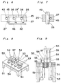
- Figs. 3 to 9 show a pipet selection device which can be employed in the dispensing machine of the present invention.
- a horizontal displacement mechanism 23 for displacing a plurality of pipets 22 horizontally and a lifting mechanism 24 for moving the pipets 22 upwardly and downwardly are provided above a base plate 21 for supporting a rectangular culture tray A.
- a plurality of wells a are arranged in a pattern of a matrix on the culture tray A.
- the pipets 22 are so provided as to correspond, in number, to the wells a of a sidewise direction of the culture tray A and are supported by a support member 25 such that the support member 25 is moved in one horizontal direction and in a vertical direction by the horizontal displacement mechanism 23 and the lifting mechanism 24, respectively.
- the wells a are arranged in a pattern of an 8 ⁇ 12 matrix on the culture tray A, 8 pipets 22 are provided.
- each of the pipets 22 is constituted by a flexible pipe 41 for sucking and supplying liquid, a rectilinear slide pipe 42 connected with one end of the flexible pipe 41 and a tip 43 attached detachably to a lower end of the slide pipe 42.
- a plurality of through-holes 26 corresponding to the wells a of the sidewise direction of the culture tray A, respectively are formed on the support member 25.
- the slide pipe 42 is loosely fitted through each of the through-holes 26 such that the through-holes 26 act as slide guides for the pipets 22, respectively.
- a plurality of apertures or slots 27 each for inserting thereinto a wedged holder 29 for holding each of the pipets 22 are formed in the support member 25 and extend from one side of the support member 25 so as to partially open into the through-holes 26, respectively.
- the holders 29 coupled with a connecting rod 28 are drawably inserted into the apertures 27, respectively.
- the connecting rod 28 is thrust by a drive means (not shown) so as to push the holders 29 into the apertures 27, respectively in the direction of the arrow B in Fig. 5.
- a wedged face of each of the holders 29 is projected into each of the through-holes 26 so as to depress the slide pipe 42 into pressing contact with a face of each of the through-holes 26 as shown in the one-dot chain lines of Fig. 5 such that the slide pipe 42 is secured in each of the through-holes 26 by each of the holders 29.
- each of the holders 29 is disengaged from the slide pipe 42 and thus, the pipets 22 can be again slid upwardly and downwardly in the through-holes 26, respectively. Therefore, at this time, height of the tip 43 can be adjusted arbitrarily within a permissible travel stroke of the slide pipe 42.
- Figs. 6 and 7 show a modification of the pipet holding mechanism of Figs. 4 and 5.
- elastic tubes 45 each having one closed end are, respectively, inserted into the apertures 27 formed in the support member 25 and are connected with a tube 46 for supplying pressurized fluid to the elastic tubes 2.
- the elastic tubes 45 are expanded so as to become larger in diameter such that the slide pipe 42 is depressed against the face of each of the through-holes 26 by each of the elastic tubes 45 as shown in Fig. 7. Therefore, in this modified pipet holding mechanism, fine adjustments of a holding force of the pipets 22 can be performed more easily than in the pipet holding mechanism of Figs.
- a bore 27 ⁇ extending in a longitudinal direction of the support member 25 is formed in the support member 25 so as to open into the through-holes 26 and a long elastic tube having one closed end is inserted into the bore 27 ⁇ such that all the slide pipes 42 are simultaneously held through expansion and contraction of this elastic tube.
- the pipet selection device further includes a stopper mechanism 50.
- the stopper mechanism 50 is constituted by a plurality of cylinders 52 fixed vertically to a frame 51, a cylinder shaft 53 extending from each of the cylinders 52, a stopper 54 secured to an upper end of the cylinder shaft 53 and a guide shaft 55 attached vertically to a lower face of a distal end portion of the stopper 54.
- the guide shaft 55 is guided by slide bearings 56 mounted in the frame 51. It is to be noted that each of the cylinders 52 can be replaced by a solenoid coil.
- the stopper mechanism 50 In the stopper mechanism 50, four cylinders 52 are spaced in the longitudinal direction of the base plate 21 from the remaining four cylinders 52 and the eight cylinders 52 are arranged in the sidewise direction of the slide plate 21 at an interval equal to a pitch of the wells a.
- a through-opening 57 for receiving the tip 43 is formed at the distal end portion of the stopper 54. Furthermore, the distal end portion of one stopper 54 protrudes in between those of the neighboring two stoppers 54 and the stoppers 54 longitudinally extend alternately oppositely in the longitudinal direction of the base plate 21 such that the through-openings 57 of the stoppers 54 are arranged in a line in the sidewise direction of the base plate 21.
- the support member 25 of the horizontal displacement mechanism 23 is displaced to the stopper mechanism 50 where the stoppers 54 of the stopper mechanism 50 are individually adjusted in height.
- the stopper 54 for the pipet 22 corresponding to the well a not requiring exchange of the liquid is raised in height, while the remaining stoppers 54 are set at a low position as shown in Fig. 8 by way of example.
- the pipet holding mechanism as a whole is lowered to a predetermined position by the lifting mechanism 24.
- the tip 43 corresponding to the high stopper 54 is inserted into the through-opening 57 of the high stopper 54 and is prevented from being further lowered through contact of a flange portion 49 of the tip 43 with the high stopper 54.
- the remaining tips 43 are further lowered without their contact with the respective stoppers 54.
- the holding force of the pipet holding mechanism is increased. Consequently, a distal end of the tip 43 of the pipet 22 corresponding to the high stopper 54 is held higher than those of the remaining pipets 22 by the pipet holding mechanism.
- the support member 25 is slightly raised by the lifting mechanism 24 and then, is returned to a predetermined position by the horizontal displacement mechanism 23, so that it becomes possible to prevent the distal end of the unnecessary tip 43 from being inserted into the well a for exchange of the liquid.
- the pipet selection device is particularly useful for an automatic incubator in which progress of culture is measured at each of the wells.
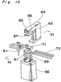
- Figs. 10 to 16 show a tip exchange device which can be employed in the dispensing machine of the present invention.
- a pipet body 83 of each of the pipets 22 is secured to a support member 84 and a jig 62 is press fitted around a distal end portion of the pipet body 83 such that a tip 61 of each of the pipets 22 is, in turn, fitted around a distal end portion of the jig 62.
- the jig 62 is formed by a rectilinear pipe made of stainless steel or the like and having a flange 63.
- the tip exchange device includes a stopper mechanism 64 having a substantially U-shaped configuration, a tip depressing mechanism 65 and a tip lifting mechanism 66.
- the stopper mechanism 64 is formed, at its front end, with a semicircular recess 85 for fitting the jig 62 thereinto.
- the flange 63 of the jig 62 is gripped in a groove 86 of the stopper mechanism 64 as shown in Fig. 11.
- the tip depressing mechanism 65 is formed by a plate formed, at its front end, with a recess 87.
- the tip depressing mechanism 65 is provided immediately below the stopper mechanism 64 and is driven upwardly and downwardly by a ball screw, etc. so as to depress the tip 61 downwardly.
- the tip lifting mechanism 66 includes a plate 70 in threaded engagement with a screw shaft 68 driven by a motor 67 and a tip magazine 71.
- Four poles 69 are mounted on the plate 70 so as to lift the tip magazine 71 through rotation of the screw shaft 68.
- the tip magazine 71 is formed with a hole for fitting the tip 61 thereinto and is transported to a predetermined position above the four poles 69 by a conveyor 72.
- a drive of the tip depressing mechanism 65 and the tip lifting mechanism 66 is not limited to the screw shaft. Thus, other mechanical devices and hydraulic or pneumatic cylinders can be, needless to say, employed for driving the tip depressing mechanism 65 and the tip lifting mechanism 66.
- the pipet body 83 is moved by the support member 84 and the jig 62 is fitted into the recess 85 of the stopper mechanism 64 such that the flange 63 of the jig 62 is gripped in the groove 86 of the stopper mechanism 64. Then, the tip depressing mechanism 65 is lowered so as to depress a flange portion of the tip 61 downwardly.
- the flange 63 of the jig 62 is gripped in the groove 86 of the stopper mechanism 64 such that vertical movement of the jig 62 is prevented, so that the tip 61 is depressed downwardly so as to be detached from the jig 62.
- the used tip 61 is dropped down to the hole of the tip magazine 71.
- Another tip magazine 71 carrying a new tip 61 is transported to a position above the tip lifting mechanism 66 and then, is lifted by the poles 69 of the tip lifting mechanism 66.
- the tip 61 is brought into contact with the distal end portion of the jig 62 as shown by the dotted lines of Fig. 11 so as to lift the jig 62.
- the tip 61 is press fitted around the distal end portion of the jig 62 so as to be secured to the jig 62. Thereafter, the poles 69 are lowered so as to return the empty pipet magazine 71 to the original position up to the conveyor 72 and the empty tip magazine 71 is held at the position until the next exchange of the tip 61.
- automatic exchange of the tip 61 can be performed.
- construction of the pipet body 83 may be designed in consideration of only a mechanism of displacement, etc. for exchange of the liquid and it is not necessary to increase rigidity or strength of the pipet body 83.
- Figs. 14, 15a and 15b show a tip exchange device for performing exchange of a plurality of the tips 61 simultaneously.
- the tip exchange device includes the stopper mechanism 64, the tip depressing mechanism 65 and the tip lifting mechanism 66 as in the tip exchange device of Fig. 10.
- the stopper mechanism 64 is formed with a plurality of the recesses 85 and the tip depressing mechanism 65 is formed with a plurality of the recesses 87.
- the tip magazine 71 has a plurality of the holes for receiving a plurality of the tips 61.
- the tips 61 are usually made of plastics. Usually, there is a considerable scatter in a diameter of a hole of the tip 61, which hole receives the jig 62. Therefore, such a phenomenon may take place that when a number of the tips 61 arranged horizontally are, respectively, pressed against the distal end portions of the jigs 62 having the flanges 63 arranged horizontally at a predetermined height by the stopper mechanism 64, the tips 61 are not fitted around the distal end portions of the jigs 62 uniformly, thereby resulting in detachment of some of the tips 61 from the corresponding jigs 62.
- the groove 86 is so formed as to have a large width such that the flange 63 of each of the jigs 62 is loosely inserted into the groove 86 and a compression spring 74 having an inside diameter larger than that of the flange 63 and having an outside diameter smaller than that of the flange 63 is wound around the pipet body 83 in the groove 86.
- the compression spring 74 may be replaced by an arrangement of Fig. 16 in which the flange 63 is depressed downwardly by a pivotal lever 76 through a compression spring 75 attached to the stopper mechanism 64 and the pivotal lever 76.
- the tips 61 are, respectively, fitted around the distal end portions of the jigs 62 uniformly even if there is a scatter in the inside diameter of the tips 61, thereby eliminating the above described undesirable phenomenon.
- the tip exchange device the tips can be exchanged automatically and an excessive force is not applied to the pipets. Therefore, rigidity of the pipet body is not required to be increased so greatly.
- the tip exchange device can be designed in view of only positioning accuracy of the pipets relative to the wells, the dispensing machine can be manufactured at low cost and easily.
Landscapes
- Chemical & Material Sciences (AREA)
- Health & Medical Sciences (AREA)
- Immunology (AREA)
- Pathology (AREA)
- Analytical Chemistry (AREA)
- Biochemistry (AREA)
- General Health & Medical Sciences (AREA)
- General Physics & Mathematics (AREA)
- Physics & Mathematics (AREA)
- Life Sciences & Earth Sciences (AREA)
- Clinical Laboratory Science (AREA)
- Chemical Kinetics & Catalysis (AREA)
- Apparatus Associated With Microorganisms And Enzymes (AREA)
- Feeding, Discharge, Calcimining, Fusing, And Gas-Generation Devices (AREA)
- Automatic Analysis And Handling Materials Therefor (AREA)
- Hand Tools For Fitting Together And Separating, Or Other Hand Tools (AREA)
- Automatic Assembly (AREA)
Claims (6)
- Ausgabemaschine, umfassend:
eine Spritzenpumpe (10);
einen Flüssigkeitstank (11);
einen Pumpenverlagerungsmechanismus (13) zum Verlagern der besagten Spritzenpumpe (10) zwischen dem besagten Flüssigkeitstank (11) und einem Behälter (4);
einen Kolbenverschiebemechanismus (14) zum Verschieben eines Kolbens der besagten Spritzenpumpe (10);
ein Ablaßsystem (16, 17) zum Ablassen der Flüssigkeit des besagten Flüssigkeitstanks (11);
ein Zufuhrsystem (2, 3, 5) zum Zuführen der Flüssigkeit zu dem besagten Flüssigkeitstank;
eine Steuervorrichtung (18), die eine Verlagerung der besagten Spritzenpumpe (10) und eine Verschiebung des besagten Kolbens der besagten Spritzenpumpe (10) und eine Betätigung des besagten Zufuhrsystems (2, 3, 5) und des besagten Ablaßsystems (16, 17) steuert;
gekennzeichnet durch
eine Waage (15) für Gewichtsmessungen des besagten Flüssigkeitstanks (11) und von Flüssigkeit in dem besagten Flüssigkeitstank (11);
wobei die besagte Steuervorrichtung (18) Mittel aufweist, durch welche sie Meß-Ausgangssignale der besagten Waage (15) ausliest;
und wobei der besagte Behälter (4) eine Mehrzahl von Senken (a) umfaßt, die in einem Matrixmuster auf einer Kulturschale (A) angeordnet sind;
und wobei die besagte Spritzenpumpe eine Mehrzahl von Pipetten (22) umfaßt, die derart vorgesehen sind, daß sie den Senken (a) einer Reihe oder einer Spalte der Matrix entsprechen;
Vorrichtungen, so daß die besagten Pipetten (22) für einen Austausch der Flüssigkeit der Senken (a) gleichzeitig bezüglich der besagten Kulturschale (A) mindestens in einer vertikalen Richtung verlagert werden, wobei die besagte Ausgabemaschine weiter eine Pipettenauswahlvorrichtung einschließt, um einen selektiven Gebrauch der besagten Pipetten (22) zu ermöglichen, wobei die besagte Pipettenauswahlvorrichtung umfaßt;
einen Pipettenhaltemechanismus (25), um die besagten Pipetten (22) einstellbar zu halten, so daß eine individuelle Lageeinstellung der besagten Pipetten (22) in vertikaler Richtung möglich ist;
einen Sperrmechanismus (50), um Lagen der distalen Enden der besagten Pipetten (22) individuell einzustellen;
wobei der besagte Sperrmechanismus (50) eine Mehrzahl von Sperrgliedern (54) einschließt, um jeweils ein Flanschteil (49) einer an jeder der besagten Pipetten (22) befestigen Spitze (43) zu halten; und
eine Mehrzahl von Antriebsgliedern (52), um jeweils die besagten Sperrglieder (54) zu verlagern, um die Höhen der besagten Sperrglieder (54) individuell einzustellen. - Ausgabemaschine nach Anspruch 1, dadurch gekennzeichnet, daß sie weiter eine Spitzenaustauschvorrichtung einschließt, um eine mittels einer Aufspannvorrichtung (62) mit einem Flansch (63) an einem distalen Ende der besagten Pipette (22) befestigte Spitze (61) auszutauschen, wobei die besagte Spitzenaustauschvorrichtung umfaßt:
eine Sperrvorrichtung (64), die mit einer ersten Ausnehmung (85) zum Aufnehmen der besagten Aufspannvorrichtung (62) versehen ist, um die besagte Pipette (22) durch ihren Eingriff mit dem besagten Flansch (63) zu sichern;
eine Spitzenabsenkvorrichtung (65), die mit einer zweiten Ausnehmung (87) zum Aufnehmen der besagten Aufspannvorrichtung (62) versehen ist, um die besagte Spitze (61) nach unten abzusenken; und
eine Spitzenhubvorrichtung (66) zum Anheben eines die besagte Spitze (61) tragenden Spitzenmagazins (71). - Ausgabemaschine nach Anspruch 2, dadurch gekennzeichnet, daß die besagte Spitzenaustauschvorrichtung weiter eine Vorrichtung (74) umfaßt, um den besagten Flansch (63) der von der besagten Sperrvorrichtung (64) gesicherten Aufspannvorrichtung (62) elastisch nach unten zu drängen.
- Ausgabemaschine nach Anspruch 1, dadurch gekennzeichnet, daß sie weiter eine Spitzenaustauschvorrichtung einschließt, um eine Mehrzahl von Spitzen (61) auszutauschen, die jeweils mittels einer Aufspannvorrichtung (62) mit einem Flansch (63) an einem distalen Ende jeder der besagten Pipetten (22) befestigt sind, wobei die besagte Spitzenaustauschvorrichtung umfaßt:
eine Sperrvorrichtung (64), die mit einer Mehrzahl von ersten Ausnehmungen (85) zum Aufnehmen der besagten Aufspannvorrichtung (62) versehen ist, um die besagten Pipetten (22) durch ihren Eingriff mit den besagten Flanschen (63) zu sichern;
eine Spitzenabsenkvorrichtung (65), die mit einer Mehrzahl von zweiten Ausnehmungen (87) jeweils zum Aufnehmen der besagten Aufspannvorrichtungen (62) versehen ist, um die besagten Spitzen (61) nach unten abzusenken; und
eine Spitzenhubvorrichtung (66) zum Anheben eines die besagten Spitzen (61) tragenden Spitzenmagazins (71). - Ausgabemaschine nach Anspruch 4, dadurch gekennzeichnet, daß die besagte Spitzenaustauschvorrichtung weiter eine Vorrichtung (74) umfaßt, um die besagten Flansche (63) der von der besagten Sperrvorrichtung (64) gesicherten Aufspannvorrichtungen (62) elastisch nach unten zu drängen.
- Ausgabemaschine nach Anspruch 4, dadurch gekennzeichnet, daß die besagte Spitzenaustauschvorrichtung weiter eine Vorrichtung (74) umfaßt, um die besagten Flansche (63) der von der besagten Sperrvorrichtung (64) gesicherten Aufspannvorrichtungen (62) elastisch nach unten zu drängen.
Priority Applications (1)
| Application Number | Priority Date | Filing Date | Title |
|---|---|---|---|
| EP92112853A EP0514948B1 (de) | 1987-03-11 | 1988-03-11 | Steuervorrichtung für relativ zu Flüssigkeitsbechern und Kulturplatten verschiebbare Pipetten |
Applications Claiming Priority (6)
| Application Number | Priority Date | Filing Date | Title |
|---|---|---|---|
| JP3552387U JPS63143198U (de) | 1987-03-11 | 1987-03-11 | |
| JP35523/87 | 1987-03-11 | ||
| JP13471687A JPS63298161A (ja) | 1987-05-29 | 1987-05-29 | 分注装置 |
| JP134716/87 | 1987-05-29 | ||
| JP14731387A JPS63313575A (ja) | 1987-06-13 | 1987-06-13 | チップ交換装置 |
| JP147313/87 | 1987-06-13 |
Related Child Applications (3)
| Application Number | Title | Priority Date | Filing Date |
|---|---|---|---|
| EP92116433.1 Division-Into | 1988-03-11 | ||
| EP92112853.4 Division-Into | 1988-03-11 | ||
| EP19920116433 Division EP0522601A3 (de) | 1987-03-11 | 1988-03-11 | Vorrichtung zum Wechseln von Pipettenspitzen |
Publications (3)
| Publication Number | Publication Date |
|---|---|
| EP0282076A2 EP0282076A2 (de) | 1988-09-14 |
| EP0282076A3 EP0282076A3 (en) | 1989-06-07 |
| EP0282076B1 true EP0282076B1 (de) | 1993-08-11 |
Family
ID=27288791
Family Applications (3)
| Application Number | Title | Priority Date | Filing Date |
|---|---|---|---|
| EP19920116433 Ceased EP0522601A3 (de) | 1987-03-11 | 1988-03-11 | Vorrichtung zum Wechseln von Pipettenspitzen |
| EP92112853A Expired - Lifetime EP0514948B1 (de) | 1987-03-11 | 1988-03-11 | Steuervorrichtung für relativ zu Flüssigkeitsbechern und Kulturplatten verschiebbare Pipetten |
| EP88103888A Expired - Lifetime EP0282076B1 (de) | 1987-03-11 | 1988-03-11 | Gerät zum Ausgeben |
Family Applications Before (2)
| Application Number | Title | Priority Date | Filing Date |
|---|---|---|---|
| EP19920116433 Ceased EP0522601A3 (de) | 1987-03-11 | 1988-03-11 | Vorrichtung zum Wechseln von Pipettenspitzen |
| EP92112853A Expired - Lifetime EP0514948B1 (de) | 1987-03-11 | 1988-03-11 | Steuervorrichtung für relativ zu Flüssigkeitsbechern und Kulturplatten verschiebbare Pipetten |
Country Status (4)
| Country | Link |
|---|---|
| US (1) | US4844298A (de) |
| EP (3) | EP0522601A3 (de) |
| CA (1) | CA1285536C (de) |
| DE (2) | DE3855446D1 (de) |
Families Citing this family (34)
| Publication number | Priority date | Publication date | Assignee | Title |
|---|---|---|---|---|
| US5213761A (en) * | 1989-04-12 | 1993-05-25 | Olympus Optical Co., Ltd. | Automatic chemical analyzer having an improved delivery mechanism |
| JPH0386251A (ja) * | 1989-08-28 | 1991-04-11 | Todoroki Sangyo Kk | 化学反応制御装置 |
| DE4023182A1 (de) * | 1990-07-20 | 1992-01-23 | Kodak Ag | Vorrichtung zum bewegen von pipettenhalter in einem analysegeraet |
| US5179983A (en) * | 1991-05-03 | 1993-01-19 | Block Medical, Inc. | Apparatus for filling multiple reservoir infusion systems |
| US5428993A (en) * | 1992-02-26 | 1995-07-04 | Toa Medical Electronics Co., Ltd. | Automatic analyzer having function of detecting remaining liquid quantity |
| US5273717A (en) * | 1992-09-30 | 1993-12-28 | Eastman Kodak Company | Self-calibrating analyzer aspirator |
| US5605798A (en) | 1993-01-07 | 1997-02-25 | Sequenom, Inc. | DNA diagnostic based on mass spectrometry |
| DE4314657A1 (de) * | 1993-05-04 | 1994-11-10 | Friedhelm Sehrt | Sicherheitsvorrichtung zur sicheren Handhabung flüssiger Stoffe mittels einer Spritze insbesondere zum Dosieren und Abfüllen gesundheitsgefährdender Flüssigkeiten |
| US5639425A (en) * | 1994-09-21 | 1997-06-17 | Hitachi, Ltd. | Analyzing apparatus having pipetting device |
| US6428955B1 (en) | 1995-03-17 | 2002-08-06 | Sequenom, Inc. | DNA diagnostics based on mass spectrometry |
| AU714880B2 (en) * | 1996-03-05 | 2000-01-13 | Syngenta Participations Ag | Testing system for chemical substances or substance mixtures |
| US5906795A (en) * | 1996-04-08 | 1999-05-25 | Sanyo Electric Co., Ltd. | Pipetting apparatus |
| EP1164203B1 (de) | 1996-11-06 | 2007-10-10 | Sequenom, Inc. | DNA-Diagnostik mittels Massenspektrometrie |
| US7285422B1 (en) | 1997-01-23 | 2007-10-23 | Sequenom, Inc. | Systems and methods for preparing and analyzing low volume analyte array elements |
| US6024925A (en) * | 1997-01-23 | 2000-02-15 | Sequenom, Inc. | Systems and methods for preparing low volume analyte array elements |
| DE69735112T2 (de) | 1996-11-06 | 2006-09-07 | Sequenom, Inc., San Diego | Verfahren zur Analyse und Vorrichtung |
| CA2276462C (en) * | 1996-12-31 | 2007-06-12 | High Throughput Genomics, Inc. | Multiplexed molecular analysis system apparatus and method |
| US6033911A (en) * | 1998-02-27 | 2000-03-07 | Hamilton Company | Automated assaying device |
| US6723564B2 (en) | 1998-05-07 | 2004-04-20 | Sequenom, Inc. | IR MALDI mass spectrometry of nucleic acids using liquid matrices |
| DE19835833A1 (de) | 1998-08-07 | 2000-02-17 | Max Planck Gesellschaft | Dosierkopf zur parallelen Bearbeitung einer Vielzahl von Fluidproben |
| US6461812B2 (en) | 1998-09-09 | 2002-10-08 | Agilent Technologies, Inc. | Method and multiple reservoir apparatus for fabrication of biomolecular arrays |
| US6309891B1 (en) * | 1998-09-09 | 2001-10-30 | Incyte Genomics, Inc. | Capillary printing systems |
| US6158484A (en) * | 1999-03-05 | 2000-12-12 | Greenlee; Wilfred E. | Dispenser for church communion liquid |
| NL1012394C2 (nl) * | 1999-06-21 | 2000-12-22 | Inst F R Biotechnologie | Werkwijze en inrichting voor het gelijktijdig en onafhankelijk van elkaar bemonsteren van ingevroren cultures van micro-organismen en/of eukaryote cellen. |
| DE10040849A1 (de) * | 2000-08-21 | 2002-03-21 | Mwg Biotech Ag | Pipettierkopf für einen Roboter mit mehreren Pipettierspitzen |
| US20020142483A1 (en) | 2000-10-30 | 2002-10-03 | Sequenom, Inc. | Method and apparatus for delivery of submicroliter volumes onto a substrate |
| US20030044320A1 (en) * | 2001-08-31 | 2003-03-06 | Shun Luo | High throughput screening micro array platform |
| JP4053562B2 (ja) * | 2005-11-25 | 2008-02-27 | ファナック株式会社 | グリス供給装置 |
| GB0616448D0 (en) * | 2006-08-18 | 2006-09-27 | Ici Plc | Methods of and apparatus for dispensing powder samples |
| WO2009039122A2 (en) | 2007-09-17 | 2009-03-26 | Sequenom, Inc. | Integrated robotic sample transfer device |
| US8550130B2 (en) * | 2010-11-10 | 2013-10-08 | Martin John Burrows | Apparatus and method for refilling reusable containers |
| CN104246514B (zh) * | 2012-04-24 | 2016-08-17 | 小滴喷射有限公司 | 喷射系统以及利用喷射系统喷射的方法 |
| CN106459866B (zh) | 2014-06-17 | 2018-11-23 | 雅马哈发动机株式会社 | 分注尖头安装头装置以及使用该头装置的移动装置 |
| CN108889354B (zh) * | 2018-07-06 | 2020-12-04 | 上海兰博贸易有限公司 | 一种高精度移液系统 |
Family Cites Families (10)
| Publication number | Priority date | Publication date | Assignee | Title |
|---|---|---|---|---|
| US2765962A (en) * | 1956-01-20 | 1956-10-09 | Nat Equip Corp | Pump construction |
| US3666420A (en) * | 1970-11-09 | 1972-05-30 | Bodenseewerk Perkin Elmer Co | Apparatus for automatically carrying out chemical analyses |
| US4199013A (en) * | 1977-04-01 | 1980-04-22 | Packard Instrument Company, Inc. | Liquid sample aspirating and/or dispensing system |
| SE8001913L (sv) * | 1980-03-11 | 1981-09-12 | Clinicon Ab | Anordning for overforing av doserade mengder reagensvetska till provror vid en analysapparat |
| FR2521304A1 (fr) * | 1982-02-09 | 1983-08-12 | Rhone Poulenc Sa | Appareil automatise pour la realisation de dosages biologiques, biochimiques ou physico-chimiques |
| US4478094A (en) * | 1983-01-21 | 1984-10-23 | Cetus Corporation | Liquid sample handling system |
| US4623008A (en) * | 1983-08-12 | 1986-11-18 | Sakata Shokai, Ltd. | Automatic dispensing system |
| US4554839A (en) * | 1983-10-14 | 1985-11-26 | Cetus Corporation | Multiple trough vessel for automated liquid handling apparatus |
| US4728501A (en) * | 1984-07-27 | 1988-03-01 | Minoru Atake | Adjustable liquid sampling apparatus |
| CH671526A5 (de) * | 1985-12-17 | 1989-09-15 | Hamilton Bonaduz Ag |
-
1988
- 1988-03-10 CA CA000561070A patent/CA1285536C/en not_active Expired - Lifetime
- 1988-03-10 US US07/166,508 patent/US4844298A/en not_active Expired - Fee Related
- 1988-03-11 EP EP19920116433 patent/EP0522601A3/de not_active Ceased
- 1988-03-11 DE DE3855446T patent/DE3855446D1/de not_active Expired - Lifetime
- 1988-03-11 EP EP92112853A patent/EP0514948B1/de not_active Expired - Lifetime
- 1988-03-11 DE DE88103888T patent/DE3883028T2/de not_active Expired - Fee Related
- 1988-03-11 EP EP88103888A patent/EP0282076B1/de not_active Expired - Lifetime
Also Published As
| Publication number | Publication date |
|---|---|
| DE3855446D1 (de) | 1996-08-29 |
| EP0282076A2 (de) | 1988-09-14 |
| DE3883028T2 (de) | 1993-12-16 |
| CA1285536C (en) | 1991-07-02 |
| EP0282076A3 (en) | 1989-06-07 |
| EP0522601A2 (de) | 1993-01-13 |
| EP0514948B1 (de) | 1996-07-24 |
| US4844298A (en) | 1989-07-04 |
| EP0522601A3 (de) | 1993-01-20 |
| EP0514948A1 (de) | 1992-11-25 |
| DE3883028D1 (de) | 1993-09-16 |
Similar Documents
| Publication | Publication Date | Title |
|---|---|---|
| EP0282076B1 (de) | Gerät zum Ausgeben | |
| EP0140247B1 (de) | Gefäss mit mehreren Löchern für eine automatische Flüssigkeitsbehandlungsanlage | |
| EP0114686B1 (de) | Vorrichtung und Verfahren zum Behandeln von flüssigen Proben | |
| US6358470B1 (en) | Automatic distribution apparatus for inserting nozzles into tips | |
| US4452899A (en) | Method for metering biological fluids | |
| US4340390A (en) | Method and apparatus for metering biological fluids | |
| EP0138205A1 (de) | Bidirektionales System zum Übertragen flüssiger Proben | |
| US5897837A (en) | Dispensing device and Immunoassay apparatus using the same | |
| EP0246632B1 (de) | Pipettiervorrichtung mit einem automatischen Mechanismus zum Wechseln der Spitzen | |
| TWI422801B (zh) | 分注量檢測方法及吸液監測器型分注裝置 | |
| US20020104389A1 (en) | Automated liquid handling device | |
| JPH0579944B2 (de) | ||
| CN116148027B (zh) | 样本制备仪 | |
| CA1144462A (en) | Discrete type automated chemical analytic apparatus | |
| EP0042337B1 (de) | Verfahren und Vorrichtung zum Dosieren biologischer Flüssigkeiten | |
| EP0292995B1 (de) | Vorrichtung zur Übertragung von Zellen | |
| GB2225223A (en) | Automated washing equipment | |
| EP0087028A1 (de) | Einrichtung zur automatischen chemischen Analyse | |
| WO1988000707A1 (en) | Liquid handling station | |
| CN213923993U (zh) | 一种分液装置 | |
| JPS5951357A (ja) | 生化学自動分析装置 | |
| CN223766314U (zh) | 一种配料系统 | |
| FI77579B (fi) | Mikrodoserande utdelningsanordning foer vaetskeprov. | |
| CN214300774U (zh) | 一种自动化滴液机 | |
| JP3395610B2 (ja) | 液体の分注方法及び分注装置 |
Legal Events
| Date | Code | Title | Description |
|---|---|---|---|
| PUAI | Public reference made under article 153(3) epc to a published international application that has entered the european phase |
Free format text: ORIGINAL CODE: 0009012 |
|
| AK | Designated contracting states |
Kind code of ref document: A2 Designated state(s): DE FR GB SE |
|
| PUAL | Search report despatched |
Free format text: ORIGINAL CODE: 0009013 |
|
| AK | Designated contracting states |
Kind code of ref document: A3 Designated state(s): DE FR GB SE |
|
| RAP1 | Party data changed (applicant data changed or rights of an application transferred) |
Owner name: SUMITOMO ELECTRIC INDUSTRIES, LIMITED |
|
| RIN1 | Information on inventor provided before grant (corrected) |
Inventor name: WASHIMI, KOUICHI C/O OSAKA WORKS Inventor name: OHOKA, AKIHIRO C/O OSAKA WORKS |
|
| RIN1 | Information on inventor provided before grant (corrected) |
Inventor name: WASHIMI, KOUICHI C/O OSAKA WORKS OF Inventor name: OHOKA, AKIHIRO C/O OSAKA WORKS OF |
|
| 17P | Request for examination filed |
Effective date: 19891103 |
|
| 17Q | First examination report despatched |
Effective date: 19910510 |
|
| GRAA | (expected) grant |
Free format text: ORIGINAL CODE: 0009210 |
|
| AK | Designated contracting states |
Kind code of ref document: B1 Designated state(s): DE FR GB SE |
|
| REF | Corresponds to: |
Ref document number: 3883028 Country of ref document: DE Date of ref document: 19930916 |
|
| ET | Fr: translation filed | ||
| PLBE | No opposition filed within time limit |
Free format text: ORIGINAL CODE: 0009261 |
|
| STAA | Information on the status of an ep patent application or granted ep patent |
Free format text: STATUS: NO OPPOSITION FILED WITHIN TIME LIMIT |
|
| 26N | No opposition filed | ||
| EAL | Se: european patent in force in sweden |
Ref document number: 88103888.9 |
|
| PGFP | Annual fee paid to national office [announced via postgrant information from national office to epo] |
Ref country code: SE Payment date: 19950315 Year of fee payment: 8 |
|
| PGFP | Annual fee paid to national office [announced via postgrant information from national office to epo] |
Ref country code: GB Payment date: 19960304 Year of fee payment: 9 |
|
| PG25 | Lapsed in a contracting state [announced via postgrant information from national office to epo] |
Ref country code: SE Effective date: 19960312 |
|
| PGFP | Annual fee paid to national office [announced via postgrant information from national office to epo] |
Ref country code: DE Payment date: 19960313 Year of fee payment: 9 |
|
| PGFP | Annual fee paid to national office [announced via postgrant information from national office to epo] |
Ref country code: FR Payment date: 19960315 Year of fee payment: 9 |
|
| REG | Reference to a national code |
Ref country code: GB Ref legal event code: 746 Effective date: 19960319 |
|
| REG | Reference to a national code |
Ref country code: FR Ref legal event code: D9 Free format text: CORRECTION |
|
| EUG | Se: european patent has lapsed |
Ref document number: 88103888.9 |
|
| PG25 | Lapsed in a contracting state [announced via postgrant information from national office to epo] |
Ref country code: GB Effective date: 19970311 |
|
| GBPC | Gb: european patent ceased through non-payment of renewal fee |
Effective date: 19970311 |
|
| PG25 | Lapsed in a contracting state [announced via postgrant information from national office to epo] |
Ref country code: FR Free format text: LAPSE BECAUSE OF NON-PAYMENT OF DUE FEES Effective date: 19971128 |
|
| PG25 | Lapsed in a contracting state [announced via postgrant information from national office to epo] |
Ref country code: DE Effective date: 19971202 |
|
| REG | Reference to a national code |
Ref country code: FR Ref legal event code: ST |