EP0282265A2 - Bilderzeugungs-Systeme - Google Patents
Bilderzeugungs-Systeme Download PDFInfo
- Publication number
- EP0282265A2 EP0282265A2 EP88302013A EP88302013A EP0282265A2 EP 0282265 A2 EP0282265 A2 EP 0282265A2 EP 88302013 A EP88302013 A EP 88302013A EP 88302013 A EP88302013 A EP 88302013A EP 0282265 A2 EP0282265 A2 EP 0282265A2
- Authority
- EP
- European Patent Office
- Prior art keywords
- data
- transducer
- coded
- vehicle
- signal
- Prior art date
- Legal status (The legal status is an assumption and is not a legal conclusion. Google has not performed a legal analysis and makes no representation as to the accuracy of the status listed.)
- Withdrawn
Links
Images

Classifications
-
- G—PHYSICS
- G01—MEASURING; TESTING
- G01S—RADIO DIRECTION-FINDING; RADIO NAVIGATION; DETERMINING DISTANCE OR VELOCITY BY USE OF RADIO WAVES; LOCATING OR PRESENCE-DETECTING BY USE OF THE REFLECTION OR RERADIATION OF RADIO WAVES; ANALOGOUS ARRANGEMENTS USING OTHER WAVES
- G01S15/00—Systems using the reflection or reradiation of acoustic waves, e.g. sonar systems
- G01S15/02—Systems using the reflection or reradiation of acoustic waves, e.g. sonar systems using reflection of acoustic waves
- G01S15/06—Systems determining the position data of a target
- G01S15/08—Systems for measuring distance only
- G01S15/10—Systems for measuring distance only using transmission of interrupted, pulse-modulated waves
- G01S15/102—Systems for measuring distance only using transmission of interrupted, pulse-modulated waves using transmission of pulses having some particular characteristics
- G01S15/104—Systems for measuring distance only using transmission of interrupted, pulse-modulated waves using transmission of pulses having some particular characteristics wherein the transmitted pulses use a frequency- or phase-modulated carrier wave
-
- G—PHYSICS
- G01—MEASURING; TESTING
- G01S—RADIO DIRECTION-FINDING; RADIO NAVIGATION; DETERMINING DISTANCE OR VELOCITY BY USE OF RADIO WAVES; LOCATING OR PRESENCE-DETECTING BY USE OF THE REFLECTION OR RERADIATION OF RADIO WAVES; ANALOGOUS ARRANGEMENTS USING OTHER WAVES
- G01S15/00—Systems using the reflection or reradiation of acoustic waves, e.g. sonar systems
- G01S15/88—Sonar systems specially adapted for specific applications
- G01S15/89—Sonar systems specially adapted for specific applications for mapping or imaging
- G01S15/8902—Side-looking sonar
- G01S15/8904—Side-looking sonar using synthetic aperture techniques
Definitions
- This invention relates to imaging systems and in particular, though not exclusively to synthetic aperture sonar systems.
- the principles described and embodied herein may however be used in other imaging systems, for example in synthetic aperture radar systems.
- High resolution rapid coverage side-scan sonar systems find applications in many areas, for example geological surveying of the sea bed, pipeline inspection, mine-hunting etc.
- the area swept by the imaging system per unit time as the transducer is towed through the water can be shown to be limited by the propagation velocity of the acoustic signal, i.e. the speed of sound in water.
- the maximum range requirement in these conventional systems determines the upper limit for the pulse repetition frequency of the transducer.
- the pulse repetition frequency determines the maximum allowable velocity of the transducer as it travels along.
- US Patent No. 4, 400, 803 discloses a system in which a series of acoustic pulses at a range of independent frequencies is transmitted at the same time.
- the echoes are filtered using band-pass filters and then demodulated for bandwidth compression in the conventional manner. It is believed however that the described system will not produce high resolution information because only a limited number of independent pulses may be accomodated in the frequency band, even if the band extends down to D.C. Depending on the maximum range and ship velocity the number of independent frequencies available may be insufficient.
- back scattering and attenuation are frequency dependent and thus the use of different frequencies for the pulses will introduce inhomogeneities into the system.
- the system includes an interferometer and it is believed to be impractical to design an interferometer capable of handling signals with such widely varying frequencies.
- an imaging system comprising:- transducer means movable along a given path and including emitter means and receiver means for emitting and receiving respectively in a direction generally transverse to said path; code generator means operable to generate and supply to said emitter means a relatively narrow band emission signal comprising a plurality of coded waveforms each having a substantially delta-like auto-correlation function and a relatively low cross-correlation function; decoder means for receiving the output signal of said receiver means and for decoding the output signal thereby to extract response data relating to each of said plurality of coded waveforms.
- a synthetic aperture sonar system comprising transducer means movable along a given path and having emitter means and receiver means for emitting and receiving a sonar signal in a direction generally transverse to said given path, code generator means for supplying to said emitter means a plurality of coded waveforms each having a substantially delta-like auto-correlation function and a relatively low cross-correlation function and decoder means for decoding the output signal of the receiver means thereby to extract response data relating to each of said plurality of coded waveforms.
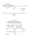
- the system comprises a towfish 10 connected to a ship 11 by means of a towing cable 12, which also serves to transmit digital data and, if required, power between the towfish and the ship.
- the towfish is towed at a velocity of 3 m/s (6 knots) at a height of roughly 15 m from the sea bed.
- the towfish incorporates an inertial navigation system 13 and associated control members and/or control jets (not shown) to cause the towfish to follow a predetermined course.
- the embodiment of the system described is intended to provide a resolution of 10 cm x 10 cm over a range of 200 m and at ship velocities of 3 m/s (6 knots).
- the shipboard elements of the system are distinguished from the elements housed on board the towfish by means of a dotted line D.
- the shipboard elements include a random access memory (RAM) 14 which stores in digital form data representing a series of coded waveforms.
- the RAM 14 stores baseband data which is later mixed up to the carrier frequency.
- the RAM 14 supplies digital data to a D/A converter 15, and the output analog signal is supplied to a filter 16 thence to a mixer 17 where it is mixed up to the carrier frequency.
- 4Br m /c digital words of RAM are required where r m is the maximum range, B is the bandwidth and c the propogation velocity.
- the output of the mixer 17 is amplified by amplifier 18 and supplied to a projector 19 via the towing cable 12.
- the RAM 14, D/A converter 15, and mixer 17 are operated under the control of a master crystal oscillator 20 and associated frequency dividers 21.
- the projector 18 is typically 20 cm long and one wavelength wide.
- the towfish 10 houses a hydrophone 22.
- the output of the hydrophone is amplified by a buffer/pre-amplifier 23 and then subjected at 24 to an active noise cancellation process designed to minimise the level of sound that the hydrophone receives directly from the projector.
- the signal supplied to the projector is attenuated or amplified at 25, subjected to a variable time delay at 26 and then combined with the output signal from the hydrophone.
- the projector and the hydrophone are placed in the nulls of each other's beam response and sound absorbing material is placed between the hydrophone and the projector.
- random noise from noise source 27 is added to the signal before being digitised by an A/D converter 28 controlled by the master oscillator 20 via the towing cable 12.
- the noise has a flat spectrum up to half the sample frequency of the A/D converter 28 and an rms value roughly corresponding to the 1-bit level of the A/D converter.
- the A/D converter digitises the signal at a sample rate which is at least twice the bandwidth signal and, in this design, it is much greater than twice the highest frequency (it oversamples).
- the sample frequency is a multiple of four times the carrier frequency. This permits easy extraction of the in-phase and quadrature signal components.
- the signal is transmitted to the ship via the towing cable 12.
- the towfish also includes an inertial navigation system 13 which supplied navigation data to the ship via the towing cable 12.
- the digitised output signal of the hydrophone is supplied to a finite impulse response (FIR) filter 29.
- FIR finite impulse response
- Figure 3 A schematic representation of the FIR filter is shown in Figure 3. Referring to Figure 3 an input signal is passed through a series of delay stages 30 which delay the input by one clock cycle. Before each delay stage, the signal is tapped and passed to a multiplier 31 where it is multiplied by a respective settable coefficient C l ??C n . The outputs of all the multipliers are supplied to an accumulator 32 of increased dynamic range where they are summed in each clock cycle to provide an output.
- the A/D Converter and the FIR filter are both controlled by the master oscillator 20.
- FIR filter chips examples include the IMS A 100 chip which has a 32-stage 16-bit data and 16 bit coefficient capability at a throughput rate of 2.5 MHz from Inmos Limited, Bristol, England, and the DSP 56200 chip from Motorola Inc. which can be programmed with 256 24-bit coefficients.
- the Motorola chip can handle 16-bit data at a rate of 10.25 MHz and has a 40 bit accumulator with programmable, automatic rounding to any desired output resolution.
- the FIR filter 29 accumulates and performs an averaging process on successive data words supplied to the filter.
- the accumulator output will correspond to the numerical total of n sequential outputs from the A/D converter.
- the analogue input to the A/D converter includes random noise at the 1-bit level
- the level of the analogue signal when untreated i.e. without the noise
- some will fall in an upper quantum band and some will fall in a lower band.
- the ratio of the numbers falling in each band will thus give an indication of the level of the untreated signal relative to the quantum level.
- the output of the accumulator will be digital signal of increased resolution representing the level of the analogue signal.
- the signal is subjected to a pulse compression process.
- the input waveform is correlated with each of the coded waveforms in turn.
- the correlation process performs the dual function of decoding and pulse compressing the response data. Because the coded waveforms input into the system are selected to have delta-like auto-correlation functions and negligible cross-correlation functions, correlation of the waveform received from the FIR filter with a particular coded waveform will extract only the response data for that particular waveform.
- data representative of replicas of the various coded waveforms is read out from the RAM 33 and used in the correlation process.
- the correlation process may also be carried out using an FIR filter supplied from RAM 33 with coefficients representing replicas of the coded waveforms supplied to the projector, and controlled so as to correlate the digitised signal from the hydrophone with the stored codes in sequence.
- the correlation may also be performed in parallel using a separate filter for each code waveform.
- the output signal is a train of data representing the response data of each of the transmitted codes.
- the response data is stored in RAM 34 in terms of range (i.e. time after transmission of each pulse) and distance along the transducer trajectory. Following pulse compression, the signal represents in serial form the response data at each of a series of points along the path of the transducer.
- the dynamic range extension technique and the pulse compression are shown as separate steps, they may be carried out using as a single step by combining the functions of pulse compression and dynamic range extension using parallel FIR filters supplied with the coded replicas from code store 33.
- the filter 29 may be controlled to perform the various averaging functions necessary for extension of the dynamic range at the same time as the correlation necessary for pulse compression.
- the data from the RAM 34 is then subjected at 35 to azimuth compression.
- the stored data is adjusted by applying complex weighting and, possibly, time delays to focus the array to take account of the spherical wavefront of the echo. It will be understood that, beyond a certain range, the curvature of the wavefront is negligible and thus that no focussing is necessary.
- the azimuth compression step requires a knowledge of the position of the towfish and this is supplied by the inertial navigation system 13 on board the towfish.
- the data may also be weighted to allow aperture shading.
- the image data is supplied to a detector 36, and then, following dynamic range reduction the image data may be displayed on e.g. a VDU 37, or supplied to a processor 38 for applying artificial intelligence or image processing techniques to interpret the image data received.
- Synthetic aperture radar techniques are generally used in side-looking configurations and make use of the fact that backscattering elements at different azimuthal positions can be distinguished by their Doppler frequency shifts.
- an enhanced range and vehicle velocity is achieved by a technique which increases the effective PRF and which overcomes the limitation described above.
- a family of large BT-product (bandwidth-time product) coded waveforms are transmitted which have the property that each waveform has a delta-like autocorrelation function and has a negligible cross-correlation function with the other members of the family.
- several effectively independent pulses are maintained in the water at the same time. In other words, it is not necessary to wait for a pulse to travel to the maximum range and return before transmitting the next pulse.
- the information relating to an individual pulse is extracted upon reception by passing the signals through the equivalent of a set of filters matched to the particular codes.
- the Nyquist criterion and relatively slow velocity of sound limit the vehicle velocity and maximum unambiguous range.
- the described embodiment overcomes this limitation by transmitting in sequence the members of a family of coded waveforms.
- the sequence should be repeated at the conventional PRF rate (or less). For reasonable length codes this means that transmissions occur continuously (i.e. the individual codes are joined 'end-to-end' or 'overlap') and this has other interesting consequences for system design.
- each code could have a duration longer than 33ms (but no longer than 0.27s).
- the signal bandwidth should be greater than about 7.5Hz and this provides an absolute lower limit on the carrier frequency.
- the coded waveforms have amplitudes and/or phases which vary as a function of time. Referring now to the factors affecting the choice of waveform the bandwidth of the signal determines the range resolution limit and so a minimum bandwidth must be maintained. To obtain good signal-to-noise ratios and high rejections between the individual codes, large BT products are used. In the design of the waveforms the full 2D ambiguity function would have to be optimised. The ideal ambiguity function would be of the so-called 'thumbtack' form. Suitable types of codes are polyphase codes or codes based upon Fourier series with the phase as a function of frequency providing the free parameters with which to optimise the ambiguity functions and cross-correlation functions. The latter, Fourier series, approach would result in a periodic waveform which should have its period made equal to the round-trip time to maximum range and back. If the individual pulses 'overlap' the transmission would consist of the sum of the pulses.
- the system may provide data for a moving target indicator. Because of the increase in the effective pulse repetition frequency, the range of the system may be increased without requiring a related decrease in the maximum unambiguous detection speed. This is because with the described system it is possible to have several coded waveforms in the water at the same time each of which is independent from the others and each of which can be decoded to obtain the respective response data.
- a radar system transmits coded waveforms having a delta-like auto-correlation function and negligible cross-correlation functions, and similar pulse compression and processing is carried out as in the sonar system.
- the advantage of this system in radar is that it is possible to maintain several mutually independent coded waveforms in the transmission medium at the same time so that the effective pulse repetition frequency can be increased without reducing the maximum range.
- the increase in pulse repetition frequency allows a MTI system to be configured in which the maximum unambiguous speed of target which may be detected is higher than previously considered theoretically possible.
Landscapes
- Engineering & Computer Science (AREA)
- Radar, Positioning & Navigation (AREA)
- Remote Sensing (AREA)
- Physics & Mathematics (AREA)
- Acoustics & Sound (AREA)
- Computer Networks & Wireless Communication (AREA)
- General Physics & Mathematics (AREA)
- Measurement Of Velocity Or Position Using Acoustic Or Ultrasonic Waves (AREA)
- Lubrication Of Internal Combustion Engines (AREA)
- Debugging And Monitoring (AREA)
- Vehicle Body Suspensions (AREA)
Applications Claiming Priority (2)
| Application Number | Priority Date | Filing Date | Title |
|---|---|---|---|
| GB08705147A GB2202329A (en) | 1987-03-05 | 1987-03-05 | Imaging systems for marine use |
| GB8705147 | 1987-03-05 |
Publications (2)
| Publication Number | Publication Date |
|---|---|
| EP0282265A2 true EP0282265A2 (de) | 1988-09-14 |
| EP0282265A3 EP0282265A3 (de) | 1989-11-15 |
Family
ID=10613360
Family Applications (1)
| Application Number | Title | Priority Date | Filing Date |
|---|---|---|---|
| EP88302013A Withdrawn EP0282265A3 (de) | 1987-03-05 | 1988-03-07 | Bilderzeugungs-Systeme |
Country Status (3)
| Country | Link |
|---|---|
| EP (1) | EP0282265A3 (de) |
| GB (1) | GB2202329A (de) |
| NO (1) | NO880982L (de) |
Cited By (11)
| Publication number | Priority date | Publication date | Assignee | Title |
|---|---|---|---|---|
| FR2645280A1 (fr) * | 1988-01-22 | 1990-10-05 | Thomson Csf | Recepteur radar, notamment pour radar ayant une antenne a formation de faisceau par le calcul |
| AU602387B2 (en) * | 1987-01-17 | 1990-10-11 | Electronic Data Systems Corporation | Synthetic aperture radar |
| EP0393269A1 (de) * | 1987-08-21 | 1990-10-24 | The Marconi Company Limited | Entfernungsmessgerät |
| US5204683A (en) * | 1988-01-22 | 1993-04-20 | Thomson-Csf | Radar receiver for a radar having a digital beam forming antenna |
| EP0625715A1 (de) * | 1993-05-21 | 1994-11-23 | STN ATLAS Elektronik GmbH | Verfahren zum Erkennen von Zielen und/oder Bestimmen ihrer Zieldaten |
| FR2755515A1 (fr) * | 1996-11-06 | 1998-05-07 | Nec Corp | Systeme de sonar a synthese d'ouverture |
| FR2769372A1 (fr) * | 1997-10-07 | 1999-04-09 | Thomson Marconi Sonar Sas | Procede de correction des effets des mouvements parasites de l'antenne dans un sonar a antenne synthetique |
| AU718492B2 (en) * | 1994-12-05 | 2000-04-13 | Midspar Systems Pty Ltd | Apparatus and method for the reduction of unwanted noise in hydrophones by use of differential displacement cancellation of the end-plugs |
| FR2865544A1 (fr) * | 2003-12-17 | 2005-07-29 | Denso Corp | Dispositif destine a detecter une distance et dispositif destine a detecter un corps |
| EP2733504A1 (de) * | 2012-11-14 | 2014-05-21 | ATLAS Elektronik GmbH | Unterwassersignalfolge, Sendeeinrichtung und Auswertevorrichtung sowie Wasserfahrzeug oder Wasserfahrzeugflotte |
| EP3605144A4 (de) * | 2017-03-22 | 2021-03-10 | Aquafusion, Ltd. | Echolotungsvorrichtung und echolotungsverfahren |
Families Citing this family (3)
| Publication number | Priority date | Publication date | Assignee | Title |
|---|---|---|---|---|
| GB2303754B (en) * | 1989-03-03 | 1997-07-02 | Marconi Gec Ltd | Ranging systems |
| US7259713B1 (en) | 1990-08-16 | 2007-08-21 | Selex Sensors And Airborne Systems Limited | Ranging systems |
| GB9927462D0 (en) * | 1999-11-22 | 2000-01-19 | Systems Engineering & Assessme | Signal processing apparatus |
Family Cites Families (11)
| Publication number | Priority date | Publication date | Assignee | Title |
|---|---|---|---|---|
| GB1459444A (en) * | 1973-01-24 | 1976-12-22 | Emi Ltd | Moving target indicators using synthetic aperture processing techniques |
| GB1455871A (en) * | 1973-04-27 | 1976-11-17 | Marconi Co Ltd | Side-looking coherent pulse radar systems |
| US4053884A (en) * | 1976-03-26 | 1977-10-11 | The United States Of America As Represented By The Secretary Of The Navy | High prf unambiguous range radar |
| US4328495A (en) * | 1980-04-28 | 1982-05-04 | Honeywell Inc. | Unambiguous doppler radar |
| FR2483086A1 (fr) * | 1980-05-22 | 1981-11-27 | Martin Philippe | Procede de traitement de signal pour radar a visee laterale et a synthese d'ouverture et circuit de mise en oeuvre |
| FR2493528A1 (fr) * | 1980-11-04 | 1982-05-07 | Thomson Csf | Systeme de detection multivoies a emission diversifiee |
| US4400803A (en) * | 1981-05-26 | 1983-08-23 | The United States Of America As Represented By The Secretary Of The Navy | Wide swath precision echo sounder |
| GB2184236B (en) * | 1981-07-27 | 1987-11-18 | Gec Avionics | Surveillance sonar for torpedo detection and guidance |
| US4513288A (en) * | 1982-03-29 | 1985-04-23 | The United States Of America As Represented By The Secretary Of The Army | Group-complementary code sets for implementing pulse-compression processing with optimum aperiodic autocorrelation and optimum cross-correlation properties |
| US4580139A (en) * | 1983-06-22 | 1986-04-01 | The United States Of America As Represented By The Secretary Of The Army | Waveform design for optimized ambiguity response |
| EP0199571A1 (de) * | 1985-04-20 | 1986-10-29 | Peter Travis Gough | Synthetisches Apertur-Sonar mit Dauerstrichsendung |
-
1987
- 1987-03-05 GB GB08705147A patent/GB2202329A/en not_active Withdrawn
-
1988
- 1988-03-04 NO NO880982A patent/NO880982L/no unknown
- 1988-03-07 EP EP88302013A patent/EP0282265A3/de not_active Withdrawn
Cited By (15)
| Publication number | Priority date | Publication date | Assignee | Title |
|---|---|---|---|---|
| AU602387B2 (en) * | 1987-01-17 | 1990-10-11 | Electronic Data Systems Corporation | Synthetic aperture radar |
| EP0393269A1 (de) * | 1987-08-21 | 1990-10-24 | The Marconi Company Limited | Entfernungsmessgerät |
| FR2645280A1 (fr) * | 1988-01-22 | 1990-10-05 | Thomson Csf | Recepteur radar, notamment pour radar ayant une antenne a formation de faisceau par le calcul |
| US5204683A (en) * | 1988-01-22 | 1993-04-20 | Thomson-Csf | Radar receiver for a radar having a digital beam forming antenna |
| EP0625715A1 (de) * | 1993-05-21 | 1994-11-23 | STN ATLAS Elektronik GmbH | Verfahren zum Erkennen von Zielen und/oder Bestimmen ihrer Zieldaten |
| US5481504A (en) * | 1993-05-21 | 1996-01-02 | Atlas Elektronik Gmbh | Method and device for determining target speed and distance with frequency modulated pulses |
| AU718492B2 (en) * | 1994-12-05 | 2000-04-13 | Midspar Systems Pty Ltd | Apparatus and method for the reduction of unwanted noise in hydrophones by use of differential displacement cancellation of the end-plugs |
| FR2755515A1 (fr) * | 1996-11-06 | 1998-05-07 | Nec Corp | Systeme de sonar a synthese d'ouverture |
| FR2769372A1 (fr) * | 1997-10-07 | 1999-04-09 | Thomson Marconi Sonar Sas | Procede de correction des effets des mouvements parasites de l'antenne dans un sonar a antenne synthetique |
| WO1999018452A1 (fr) * | 1997-10-07 | 1999-04-15 | Thomson-Marconi Sonar S.A.S. | Procede de correction des effets des mouvements parasites de l'antenne dans un sonar a antenne synthetique |
| US6304513B1 (en) * | 1997-10-07 | 2001-10-16 | Thomson Marconi Sonar S.A.S. | Method for correcting effects of an antenna interfering movements in a sonar with synthetic antenna |
| FR2865544A1 (fr) * | 2003-12-17 | 2005-07-29 | Denso Corp | Dispositif destine a detecter une distance et dispositif destine a detecter un corps |
| US7496157B2 (en) | 2003-12-17 | 2009-02-24 | Denso Corporation | Apparatus for detecting a distance and apparatus for detecting a body |
| EP2733504A1 (de) * | 2012-11-14 | 2014-05-21 | ATLAS Elektronik GmbH | Unterwassersignalfolge, Sendeeinrichtung und Auswertevorrichtung sowie Wasserfahrzeug oder Wasserfahrzeugflotte |
| EP3605144A4 (de) * | 2017-03-22 | 2021-03-10 | Aquafusion, Ltd. | Echolotungsvorrichtung und echolotungsverfahren |
Also Published As
| Publication number | Publication date |
|---|---|
| GB8705147D0 (en) | 1987-08-05 |
| NO880982L (no) | 1988-09-06 |
| EP0282265A3 (de) | 1989-11-15 |
| NO880982D0 (no) | 1988-03-04 |
| GB2202329A (en) | 1988-09-21 |
Similar Documents
| Publication | Publication Date | Title |
|---|---|---|
| US12405374B2 (en) | Hyperspectral sonar | |
| US4456982A (en) | Imaging system with multiple, simultaneous transmissions | |
| US7944390B2 (en) | High-resolution synthetic aperture side view radar system used by means of digital beamforming | |
| EP0282265A2 (de) | Bilderzeugungs-Systeme | |
| US4403314A (en) | Active detection system using simultaneous multiple transmissions | |
| US7215599B2 (en) | Ultrasonic transmitter, ultrasonic transceiver and sonar apparatus | |
| EP4145176B1 (de) | Sonardatenkompression | |
| CA1151283A (en) | Method for shaping and aiming narrow beams | |
| US6427531B1 (en) | Active acoustic phased array antenna system | |
| US4992796A (en) | Computed-interferometry radar system with coherent integration | |
| CN112055819A (zh) | 无线电或声波检测器、发射器、接收器及其方法 | |
| US5302955A (en) | Apparatus for combining data produced from multiple radars illuminating a common target area | |
| US4400803A (en) | Wide swath precision echo sounder | |
| US4403311A (en) | Acoustic imaging system | |
| US11280903B2 (en) | Acoustic doppler system and method | |
| JP2002214341A (ja) | 合成開口ソーナー及び合成開口処理方法 | |
| IL112508A (en) | Signal processing for ultra- wideband impulse radar | |
| JPS63106585A (ja) | 像形成装置 | |
| US4953143A (en) | Multiple frequency synthetic aperture sonar | |
| US5295118A (en) | Synthetic aperture side-looking sonar apparatus | |
| Gough | A synthetic aperture sonar system capable of operating at high speed and in turbulent media | |
| US4961174A (en) | High data rate continuous wave towed sonar | |
| GB2134741A (en) | Radar apparatus | |
| US6771561B2 (en) | Sonar system especially for shallow water application such as in littoral environments | |
| Newhouse et al. | Introduction to ultrasonic pseudo-random code systems |
Legal Events
| Date | Code | Title | Description |
|---|---|---|---|
| PUAI | Public reference made under article 153(3) epc to a published international application that has entered the european phase |
Free format text: ORIGINAL CODE: 0009012 |
|
| AK | Designated contracting states |
Kind code of ref document: A2 Designated state(s): BE FR GB NL SE |
|
| PUAL | Search report despatched |
Free format text: ORIGINAL CODE: 0009013 |
|
| AK | Designated contracting states |
Kind code of ref document: A3 Designated state(s): BE FR GB NL SE |
|
| STAA | Information on the status of an ep patent application or granted ep patent |
Free format text: STATUS: THE APPLICATION IS DEEMED TO BE WITHDRAWN |
|
| 18D | Application deemed to be withdrawn |
Effective date: 19900516 |