EP0282268B1 - Optische Schaltmatrix - Google Patents
Optische Schaltmatrix Download PDFInfo
- Publication number
- EP0282268B1 EP0282268B1 EP88302018A EP88302018A EP0282268B1 EP 0282268 B1 EP0282268 B1 EP 0282268B1 EP 88302018 A EP88302018 A EP 88302018A EP 88302018 A EP88302018 A EP 88302018A EP 0282268 B1 EP0282268 B1 EP 0282268B1
- Authority
- EP
- European Patent Office
- Prior art keywords
- optical
- input
- optical switches
- output
- switches
- Prior art date
- Legal status (The legal status is an assumption and is not a legal conclusion. Google has not performed a legal analysis and makes no representation as to the accuracy of the status listed.)
- Expired - Lifetime
Links
- 230000003287 optical effect Effects 0.000 title claims description 213
- 239000011159 matrix material Substances 0.000 title claims description 85
- 239000000758 substrate Substances 0.000 claims description 4
- 238000010586 diagram Methods 0.000 description 7
- 230000006872 improvement Effects 0.000 description 6
- 230000000694 effects Effects 0.000 description 5
- 238000003491 array Methods 0.000 description 4
- 230000008901 benefit Effects 0.000 description 2
- 230000000593 degrading effect Effects 0.000 description 2
- 230000003292 diminished effect Effects 0.000 description 2
- 238000000926 separation method Methods 0.000 description 2
- 229910003327 LiNbO3 Inorganic materials 0.000 description 1
- 241000233805 Phoenix Species 0.000 description 1
- 230000008859 change Effects 0.000 description 1
- 230000000052 comparative effect Effects 0.000 description 1
- 150000001875 compounds Chemical class 0.000 description 1
- 230000008878 coupling Effects 0.000 description 1
- 238000010168 coupling process Methods 0.000 description 1
- 238000005859 coupling reaction Methods 0.000 description 1
- 238000005516 engineering process Methods 0.000 description 1
- 239000000463 material Substances 0.000 description 1
- 230000004048 modification Effects 0.000 description 1
- 238000012986 modification Methods 0.000 description 1
- 239000013307 optical fiber Substances 0.000 description 1
- 230000009467 reduction Effects 0.000 description 1
- 238000004904 shortening Methods 0.000 description 1
- 239000007787 solid Substances 0.000 description 1
Images







Classifications
-
- H—ELECTRICITY
- H04—ELECTRIC COMMUNICATION TECHNIQUE
- H04Q—SELECTING
- H04Q11/00—Selecting arrangements for multiplex systems
- H04Q11/0001—Selecting arrangements for multiplex systems using optical switching
- H04Q11/0005—Switch and router aspects
-
- G—PHYSICS
- G02—OPTICS
- G02B—OPTICAL ELEMENTS, SYSTEMS OR APPARATUS
- G02B6/00—Light guides; Structural details of arrangements comprising light guides and other optical elements, e.g. couplings
- G02B6/10—Light guides; Structural details of arrangements comprising light guides and other optical elements, e.g. couplings of the optical waveguide type
- G02B6/12—Light guides; Structural details of arrangements comprising light guides and other optical elements, e.g. couplings of the optical waveguide type of the integrated circuit kind
- G02B2006/12083—Constructional arrangements
- G02B2006/12119—Bend
-
- G—PHYSICS
- G02—OPTICS
- G02B—OPTICAL ELEMENTS, SYSTEMS OR APPARATUS
- G02B6/00—Light guides; Structural details of arrangements comprising light guides and other optical elements, e.g. couplings
- G02B6/10—Light guides; Structural details of arrangements comprising light guides and other optical elements, e.g. couplings of the optical waveguide type
- G02B6/12—Light guides; Structural details of arrangements comprising light guides and other optical elements, e.g. couplings of the optical waveguide type of the integrated circuit kind
- G02B2006/12133—Functions
- G02B2006/12145—Switch
-
- H—ELECTRICITY
- H04—ELECTRIC COMMUNICATION TECHNIQUE
- H04Q—SELECTING
- H04Q11/00—Selecting arrangements for multiplex systems
- H04Q11/0001—Selecting arrangements for multiplex systems using optical switching
- H04Q11/0005—Switch and router aspects
- H04Q2011/0052—Interconnection of switches
Definitions
- This invention relates to optical matrix switches for performing matrix switching operations on optical input signals, and generating optical output signals.
- Matrix switches of this type are commonly used in optical fibre carrier networks.
- Optical matrix switches have been known to consist of sixteen 2 x 2 optical switches arranged in a 4 x 4 square matrix array on a LiNbO3 substrate. Serially and diagonally arranged waveguides interconnect the optical switches.
- the number of optical switches in such a matrix switch is the same as in the most elementary optical matrix switch, in which the optical switches are arranged in a square matrix and are connected orthogonally, but this arrangement connects any given pair of input and output ports through a constant number of optical switch means and requires only half as many means as the most elementary optical matrix switch in the worst case. It therefore has the advantages of low loss and reduced crosstalk, although the arrangement is not entirely free from crosstalk.
- An improved type of optical matrix switch in which crosstalk does not occur comprises 2 arrays of sixteen 2 x 2 optical switches arranged in a 4 x 4 square matrix. One of the arrays is an input array, the other is an output array. The 2 x 2 optical switches at the crosspoints of the matrix arrays on the input and output sides are interconnected by waveguides. This arrangement enables the information entering the input ports to undergo matrix switching and appear at the output ports with almost no crosstalk at all, because the same 2 x 2 optical switch never receives differing input information.
- An alternative optical matrix switch that has been proposed has reduced crosstalk, and comprises approximately the same number of optical switches as an optical matrix switch with an elementary square matrix configuration, but this matrix switch is small in size and has only a small number of optical switches on the route from a given input port to a given output port.
- This arrangement comprises a combination of 2 x 2 optical switches used successively in a 1 x 2 configuration, a 2 x 2 configuration, and a 2 x 1 configuration.
- a major feature of this type of optical matrix switch is its reduced size, but this matrix switch suffers from the disadvantage that light loss occurs at the points of intersection of the waveguides, thereby degrading the crosstalk characteristics.
- the invention provides an optical matrix switch with 2 i+1 input ports (where i is a natural number) and 2 i+1 output ports which optical matrix switch performs a matrix selection on optical input signals received at the input ports and outputs them as optical output signals at the output ports, and which optical matrix switchcomprises an i-stage input branching tree consisting of 1 x 2 branching means connected in a tree configuration, for dividing the optical input signals into 2 (2i+1) branched signals; a double tree including 2 2i 2 x 2 optical switches connected in series to the input branching tree so that each 2 x 2 optical switch receives two branched signals from different input ports and generates switch output signals at a selected one of its two outputs; an i-stage output merging tree consisting of 2 x 1 merging means connected in a tree configuration for receiving the switch output signals from the 2 x 2 optical switches and generating optical output signals at the 2 i+1 output ports.
- Fig. 1 is an oblique view showing the structure of an optical matrix switch according to the prior art, which has sixteen 2 x 2 optical switches 91 arranged in a 4 x 4 square matrix array.
- Each of four input ports 1a, 1b, 1c and 1d feeds a row of 2 x 2 optical switches 91.
- One set of the inputs and outputs of the optical switches in each row are connected in series via waveguides 93.
- the outputs of the last column of 2 x 2 optical switches 91 are connected to the four output ports 2a, 2b, 2c and 2d.
- each 2 x 2 optical switch 91 that is not connected in series in its row is linked via a waveguide 93 to the input of a 2 x 2 optical switch 91 in the next column that is not connected in series in its row, thus creating diagonal interconnections between the 2 x 2 optical switches 91.
- Information entering one of the input ports 1a, 1b, 1c or 1d is switched by the 2 x 2 optical switches at the crosspoints of the matrix, each of which can be in either the cross or bar state.
- Crosstalk occurs at the third 2 x 2 optical switch 91 in the fourth row when information entering at input port 1b and following the solid arrows meets information entering at input port 1d and following the dotted arrows.
- Fig. 2 shows an oblique view of an alternative optical matrix switch according to the prior art comprising sixteen 2 x 2 optical switches 94 arranged in a 4 x 4 square matrix array connected to the input ports 1a, 1b, 1c and 1d, and a similar array of 2 x 2 optical switches 95 connected to the output ports 2a, 2b, 2c and 2d.
- the 2 x 2 optical switches 94 and 95 at the crosspoints of the matrix arrays on the input and output sides are interconnected by waveguides 93 in a pattern that shifts one row lower in the output array for each successive column in the input array.
- Information entering the input ports undergoes matrix switching, and the information is output at the output ports with almost no crosstalk at all, because the same 2 x 2 optical switch never receives differing input information.
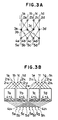
- Fig. 3A and Fig. 3B show, respectively, 4 x 4 and 8 x 8 configurations of an alterantive optical matrix switch according to prior art in which an attempt has been made to reduce the number of optical switches required whilst maintaining the crosstalk characteristics.
- the configuration in Fig. 3A comprises input waveguides 1a through 1d, output waveguides 5a through 5d, 2 x 2 optical switches used in the 1 x 2 configuration (2a through 2d) and 2 x 1 configuration (4a through 4d), and 2 x 2 optical switches 3a through 3d. Circles represent optical switches; lines represent waveguides linking the switches. These optical switches and waveguides are fabricated on the same substrate.
- the configuration in Fig. 3B comprises input waveguides 1a through 1h, output waveguides 5a thorugh 5 h, 2 x 2 optical switches used in the 1 x 2 configuration 2 1a through 2 1h , 2 x 2 optical switches used in the 2 x 1 configuration 4 2a through 4 2h , and 4 x 4 optical switches 7a through 7d consisting of 2 x 2 optical switches structured as in Fig. 3A.
- the input waveguides 1a through 1h and 1 x 2 optical switches 2 1a through 2 1b in Fig. 3B can be divided into two groups: those labelled with subscripts from a through d and those labelled with subscripts from e through h.
- the output 2 x 1 optical switches 4 2a through 4 2h and the output waveguides 5a through 5 h can also be divided into two groups.
- the input ports 1a thorugh 1d are selectively connected by the input optical switches 2 1a through 2 1d to one of the 4 x 4 optical switches 7a and 7b connected to the two output port groups.
- the input ports 1e through 1 h are selectively connected by the input optical switches 2 1e through 2 1h to one of the 4 x 4 optical switches 7c and 7d connected to the two output port groups.
- the output 2 x 1 optical switches 4 2a through 4 2h selected one of the 4 x 4 optical switches 7a and 7b or 7c and 7d connected to the two groups of input ports 1a through 1d and 1e through 1h and connect them to the output ports.
- the output port that is selected depends on the operation of the 4 x 4 optical switches 7a through 7d.
- a problem encountered by the configuration described above is that light loss occurs at the points of intersection of the waveguides, degrading the crosstalk characteristics.
- the light signal 41 travelling through the waveguide 7c-4 2a in Fig. 3C If the light signal 42 is present in the waveguide 7a-4 2b , crosstalk will occur at the point of intersection 43 of the waveguides 41 and 42.
- the amount of crosstalk into the waveguide 7a-4 2a at the point of intersection 43 is 20dB with respect to the strength of the light signal 42, and that the loss at the points of intersection 44a through 44f and 43 is 2dB.
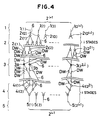
- Fig. 4 is a functional schematic diagram of one embodiment of the present invention.
- Optical input signals enter at the 2 i+1 input ports 1 (1 (1) , 1 (2) , 1 (3) , ..., 1 (2 i+1 ) , where i is a natural number).
- the input ports 1 are connected to an i-stage input branching tree 2 consisting of 1 x 2 branching means 2 1(1) , 2 1(2) , ..., 2 i(1) , 2 i(2) , ..., 2 i(2 2i ) .
- From the i-th stage, comprising the 1 x 2 branching means 2 i(1) , 2 i(2) , ..., 2 i(2 2i ) are obtained 2 (2i+1) branched signals.
- 2 2i 2 x 2 optical switches 3 (3 (1) , 3 (2) , ..., 3 (2 2i ) ) which, together with the input branching tree 2, form a compound tree.
- the two inputs of each of the 2 2i 2 x 2 optical switches 3 are connected so as to receive branched signals from different input ports.
- Each of the 2 x 2 optical switches 3 also has two outputs.
- the 2 (2i+1) outputs from the collection of all the 2 x 2 optical switches 3 are connected to the inputs of the 2 2i 2 x 1 merging means 4 1(1) , 4 1(2) , ..., 4 1(1 2i ) in the first stage of an i-stage merging tree 4, and thence through the i-stage merging tree to the inputs of the i-th stage of 2 x 1 merging means 4 i(1) , 4 i (2), ..., 4 i(2 i+1 ) .
- the outputs of the merging means 4 i in the i-th stage are connected to 2 i+1 output ports 5 (5 (1) , 5 (2) , ..., 5 (2 i+1 ) ).
- the interconnections among the input ports 1, the input branching tree 2, the 2 x 2 optical switches 3, the merging tree 4, and the output ports 5 consist of waveguides 6, and are configured so that the optical input signal applied to any input port (1a, say) can reach all of the output ports 5 (5 (1) , 5 (2) , ..., 5 (2 i+1 ) ) via the input branching tree 2, the 2 x 2 optical switches 3, and the merging tree 4.
- Additional dummy waveguides marked DW in the drawing are provided, crossing the above waveguides at dummy points of intersection. These dummy points of intersection are placed so as to equalize the total number of points of intersection (the sum of the number of real points of inter-section and the number of dummy points of intersection) on any light propagation path from an input port to an output port.
- the input optical signals received at the 2 i+1 input ports 1 (1 (1) , 1 (2) , ..., 1 (2 i+1 ) ) are divided into 2 (2i+1) branched signals by the i-stage input branching tree 2 consisting of stages of 1 x 2 branching means (2 i(1) , 2 i(2) , ..., 2 i(2 2i ) ), and fed to the 2 2i 2 x 2 optical switches 3 (3 (1) , 3 (2) , ..., 3 (2 2i ) ).
- Each 2 x 2 optical switch 3 receives at its two inputs branched signals from two different input ports, selects one of its two outputs, and outputs a switch output signal.
- the first stage of 2 x 1 merging means (4 1(1) , 4 1(2 ), ..., 4 1(2 2i ) ) connected to the outputs of the 2 x 2 optical switches 3 receives the switch output signals and merges them into outputs that are fed to the second stage of 2 x 1 merging means (4 2(1) , 4 2(2) , ..., 4 2(2 2i-1 ) ).
- the merged signals continue to travel through the i-stage merging tree 4 unit they become the optical outputs from the i-th stage of 2 x 1 merging means (4 i(1) , 4 i(2) , ..., 4 i(2 i+1 ) ) to the 2 i+1 output ports 5.
- Fig. 5A is a schematic diagram of the embodiment; Fig. 5B shows the operation of the 2 x 2 optical switches in the double tree.
- the optical input signals at the four input ports 1a, 1b, 1c, and 1d are connected through an input branching tree consisting of only one stage of 1 x 2 branching means 2a, 2b, 2c, and 2d to the eight inputs of the four 2 x 2 optical switches 3a, 3b, 3c, and 3d.
- the eight outputs of the 2 x 2 optical switches 3a, 3b, 3c, and 3d are connected through an output merging tree consisting of only one stage of 2 x 1 merging means 4a, 4b, 4c and 4d to the four output ports 5a, 5b, 5c, and 5d.
- the four 2 x 2 optical switches 3a, 3b, 3c, and 3d form the elements of a double tree, being at once the second stage of the tree structure with respect to the input branching tree and the pre-stage tree elements of the 2 x 1 merging means 4a, 4b, 4c, and 4d forming the output merging tree.
- the manner in which the outputs of the input branching tree and the inputs of the 2 x 2 optical switches, and the output of the 2 x 2 optical switches and the inputs of the output merging tree are connected via waveguides 6 is as follows.
- One output of the 1 x 2 branching means 2a and one output of the 1 x 2 branching means 2b in the input branching tree are connected to the inputs of the 2 x 2 optical switch 3a.
- the other outputs of the 1 x 2 branching means 2a and the other input of the 1 x 2 branching means 2b in the input branching tree are connected to the inputs of the 2 x 2 optical switch 3b.
- One output of the 1 x 2 branching means 2c and one output of the 1 x 2 branching means 2d are connected to the inputs of the 2 x 2 optical switch 3c.
- the other output of the 1 x 2 branching means 3c and the other output of the 1 x 2 branching means 2d in the input branching tree are connected to the inputs of the 2 x 2 optical switch 3d.
- the outputs of the 2 x 2 optical switch 3a are connected to one input of the 2 x 1 merging means 4a and one input of the 2 x 1 merging means 4b in the output merging tree.
- the outputs of the 2 x 2 optical switch 3b are connected to one input of the 2 x 1 merging means 4c and one input of the 2 x 1 merging means 4d.
- the outputs of the 2 x 2 optical switch 3c connected to the other input of the 2 x 1 merging means 4a and the other input of the 2 x 1 merging means 4b in the input branching tree.
- the outputs of the 2 x 2 optical switch 3d are connected to the other input of the 2 x 1 merging means 4c and the other input of the 2 x 1 merging means 4d.
- Additional dummy waveguides marked DW in the drawing are provided, crossing the above waveguides at dummy points of intersection. These dummy points of intersection are placed so as to equalize the total number of points of intersection (the sum of the number of real points of intersection and the number of dummy points of intersection) on any light propagation path from an input port to an output port.
- the optical input signals at the input ports 1a, 1b, 1c, and 1d are branched by the branching tree consisting of the 1 x 2 branching means 2a, 2b, 3c, and 3d and become the inputs to the 2 x 2 optical switches 3a, 3b, 3c, and 3d.
- the two inputs to each of the 2 x 2 optical switches 3a, 3b, 3c, and 3d are branched signals from different input ports 1a, 1b, 1c, and 1d.
- the switch output signals from the 2 x 2 optical switches 3a, 3b, 3c, and 3d are combined by the output merging tree and supplied as optical output signals to the output ports 5a, 5b, 5c, and 5d.
- the 2 x 2 optical switch 3 has a pair of inputs 31a and 31b and a pair of outputs 32a and 32b, and operates in a way equivalent to the double tree in the right half of Fig. 5B by coupling an input to a selected output.
- this double tree comprises a 1 x 2 optical switch 33a that branches the input 31a, two optical switches 34a and 34b that are connected in tree fashion, a 1 x 2 optical switch 33b that branches the input 31b, and optical switches 34a and 34b that receive and merge the outputs of the 1 x 2 optical switches 33a and 33b.
- the 2 x 2 optical switch in the left part of Fig. 5B is both a branching means that forms part of the branching tree and a merging means that forms part of the merging tree. For this reason the tree is referred to as a double tree.
- the 4 x 4 optical matrix switch in Fig. 5A is equivalent to a so-called nonblocking 4 x 4 optical matrix switch that can direct an optical input signal at any of the input ports 1a, 1b, 1c, and 1d through the input branching tree, the 2 x 2 optical switches of the double tree, and the output merging tree to all of the output ports 5a, 5d, 5c, and 5d.
- the input branching tree and the output merging tree divide and combine information with almost no crosstalk.
- a slight increase in crosstalk occurs in the single stage of 2 x 2 optical switches 3a, 3b, 3c, and 3d in the double tree, because each optical switch replaces parts of both trees, but this arrangement achieves a simple, compact configuration.
- the light signal entering 3b from the optical switch 2a has already passed through one point of intersection in Fig. 3A, so if (as in Fig. 3A) there is no dummy waveguide 11b, the strength of this light signal will differ from that of the light signal entering 3b from the optical switch 2b.
- This invention thus provides the same effect as at point of intersection.
- the paths by which light can enter the two input ports of one of the switches 3a, 3b, 3c, or 3d are always adjacent, so if there are no dummy waveguides, one path will always have an excess of log2n-1 points of intersection.
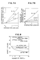
- Fig. 7A shows the degree of improvement in the crosstalk/signal strength ratio in relation to the crosstalk arising at the optical switches 3a through 3d.
- Fig. 7B shows the degree of improvement in the crosstalk/signal strength ratio in relation to the crosstalk arising at the points of intersection in the worst case.
- Fig. 8 shows the worst case of the S x R value after the improvement made by this invention. Both the all-active and intermediate types show improvement in characteristics over the elementary square matrix.
- the input branching tree has two stages of 1 x 2 branching means 2 1a , 2 1b , ..., 2 2a , ..., 2 2p , which feed thirty-two branched signals to sixteen 2 x 2 optical switches 3a, 3b, ..., 3p and the thirty-two switch output signals enter a two-stage output merging tree consisting of the 2 x 1 merging means 4 1a , 4 1b , ..., 4 1p , 4 2a , ..., 4 2h , the output signals of which are connected to the eight output ports 5a, 5b, ..., 5h.
- the configuration in Fig. 9 can be viewed as consisting of four unit matrices 7a, 7b, 7c, and 7d, each equivalent in configuration to the 4 x 4 optical matrix switch of Fig. 5A.
- the four units are arranged in parallel, and the input ports 1a, 1b, ..., 1h are divided into two groups of four ports each, 1a to 1d and 1e to 1h, the inputs from which are distributed to the four unit matrices 7 by the first stage of 1 x 2 branching means 2 1a , 2 1b , ..., 2 1h .
- Fig. 10 shows an optical matrix switch in which this unit configuration is generalized.
- the outputs from the unit matrices are combined by the 2 x 1 merging means 4 (1) , ..., 4 (2 i ) of 4 (2 i +1) , ..., 4 (2 i+1 ) , resulting in output signals at the 2 i+1 output ports 5(1), ..., 5(2 i+1 ).
- Each of the 2 i x 2 i unit matrices from 7a to 7d has the structure shown in Fig. 10 with i replaced by i-1.
- the unit matrix is the 2 x 2 optical switch shown in Fig. 5B.
- the 4 x 4 optical matrix switch in Fig. 5A can also be viewed as an instance of the generalized configuration in Fig. 10, in which the unit matrices are 2 x 2 optical switches.
- the inventive concept of providing dummy waveguides to equalize the total number of points of intersection can be applied to various other structures of optical matrix switches.
- Fig. 11 shows another example of a 4 x 4 optical matrix switch.
- the circuit configuration in Fig. 11 has a function similar to that of the circuit shown in Fig. 5A.
- the output merging means 104a, 104b, 104c, and 104d in Fig. 11 correspond to 4a, 4c, 4b, and 4d in that order in Fig. 5A, while the output ports 105a, 105b, 105c, and 105d correspond to the output ports 5a, 5c, 5b, and 5d.
- Fig. 12 shows a further example of a 4 x 4 optical matrix switch.
- output merging means 204a, and 204d positioned outside of the array of merging means 204a to 204d are connected to 2 x 2 switches 3b and 3c positioned inside of the array of four switches 3a to 3d, and output merging means 204b and 204c positioned inside are connected to the 2 x 2 switches 3a and 3d positioned outside.
- the arrangement of Fig. 12 has a particular advantage in that all the four inputs are transmitted to different outputs when the all the 2 x 2 switches are in the same state, i.e., either in the cross state in which the light propagates straightly or in the bar state in which the light is totally reflected, in other words, when the same control signal is applied to the control electrodes of all the 2 x 2 switches.
- the optical matrix switch can be constructed by providing on/off switches 35a and 35b at the two inputs of the 2 x 2 optical switch 3, as in Fig. 13. If both the input branching tree and output merging tree are configured from passive branching and merging means, the optical matrix switch has a compact overall structure, with the length of just two optical switch stages. The saving in space is particularly noticeable when there are eight or more input ports.
- Fig. 14A to Fig. 14C show other embodiments of this invention.
- the waveguide interconnections in these embodiments are identical to those in Fig. 11, Fig. 5A, and Fig. 9, except that some of the waveguides connecting the optical switches, branching means, and merging means are bent. If we refer to the direction of the straight lines connecting corresponding members of the equal numbers of input and output ports as the longitudinal direction and the direction perpendicular to this direction as the transverse direction, then some or all of the waveguides 61 connecting optical switches, branching means, and merging means that are positioned differently in the transverse direction follow bent paths.
- the bent paths take the form of piecewise circular arcs as illustrated in the drawing. Use of bent waveguides enables the longitudinal dimensions of the optical matrix switch to be shortened.
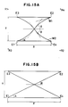
- Figs. 15A and 15B show two intersecting bent waveguides W1 and W2.
- the bent portions are combinations of circular arcs with centers at R1 to R4.
- the optical switches, branching means, merging means, and other elements E1 to E4 are aligned in the longitudinal and transverse directions are separated by distances of Y in the transverse direction.
- the distance between elements in the longitudinal direction be X when bent waveguides are used and X ⁇ when straight waveguides are used.
- the dimensions X and X ⁇ are limited by the angle of divergence 2 ⁇ at the points of branching and the angle of intersection 2 ⁇ at the point of intersection.
- the angle of divergence 2 ⁇ must normally be less than about 2 degrees, and cannot be made larger than 4 degrees even by the use of special materials. To avoid crosstalk the angle of intersection 2 ⁇ must be at least 4 to 7 degrees.
- the bent waveguides permit the angle of intersection 2 ⁇ to be larger and the distance X between elements to be shorter.
- straight waveguides the angle of intersection and the angle of divergence are equal, so special optical switches are required to achieve the necessary angle of intersection (4 to 7 degrees); but with bent waveguides the angle of divergence can be less than the angle of intersection, so special optical switches are not needed.
- Figs. 17A, 17B, 17C, 18A and 18B show the results of some preliminary calculations of the total lengths of various optical matrix switches.
- Fig. 17A is plotted with respect to the number of ports.
- Fig. 17A treats the case in which the branching means and merging means are configured from passive means without using optical switches (so ls, the length of the switches, is 0).
- Figs. 18A and 18B the total length of a 16 x 16 optical matrix switch as a function of the radius of curvature.
- Fig. 18A is for the all-active case;
- Fig. 18B is for the intermediate case.
- dummy waveguides DW are provided, forming dummy points of intersection so that the number of points of intersection passed through is the same for light following any path.
- input signals from input ports enter an input branching tree consisting of 1 x 2 branching means
- switch output signals are obtained from the 2 x 2 optical switches of a double tree that is connected to the input branching tree, these enter an output merging tree consisting of 2 x 1 merging means, and output signals are obtained at the output ports.
- the number of optical switch stages that information entering at the input ports must pass through can be 2log22 i+1 - 1, so light loss is reduced.
- this invention enables the optical matrix switch to be constructed with only 3(i+1)2/4 optical switches as compared with the normal tree structure, and permits an optical matrix switch to be configured with about 5/4 as many optical switches as compared with the elementary square matrix array, so it is capable of providing a compact optical matrix switch with excellent selection capabilities and little crosstalk.
- dummy points of intersection are formed with dummy waveguides to equalize the total number of points of intersection on any light propagation path, so the light obtained at the output ports is nearly uniform.
- the length of the optical matrix can be still further reduced.
Landscapes
- Engineering & Computer Science (AREA)
- Computer Networks & Wireless Communication (AREA)
- Use Of Switch Circuits For Exchanges And Methods Of Control Of Multiplex Exchanges (AREA)
- Optical Integrated Circuits (AREA)
Claims (4)
- Optischer Matrixschalter mit 2i+1 Eingangsanschlüssen (1) (wobei i eine natürliche Zahl ist) und 2i+1 Ausgangsanschlüsse (5), wobei der optische Matrixschalter eine Matrixauswahl optischer Eingangssignale durchführt, die an den Eingangsanschlüssen (1) empfangen werden, und diese als optische Ausgangssignale an den Ausgangsanschlüssen (5) ausgibt, und wobei der optische Matrixschalter aufweist
einen i-stufigen Eingangsverzweigungsbaum (2), der aus einer 1 x 2 Verzweigungseinrichtungen besteht, die in einer Baumkonfiguration verbunden sind, zum Teilen der optischen Eingangssignale in 2(2i+1) verzweigte Signale;
einen Doppelbaum (3), der 22i 2 x 2 optische Schalter enthält, die in Serie mit dem Eingangsverzweigungsbaum (2) so verbunden sind, daß jeder optische 2 x 2 Schalter zwei verzweigte Signale von unterschiedlichen Eingangsanschlüssen empfängt und Schalterausgangssignale an einem ausgewählten seiner zwei Ausgänge erzeugt;
einen i-stufigen Ausgangsmischbaum, der aus 2 x 1 Mischeinrichtungen (4) besteht, die in einer Baumkonfiguration zum Empfangen der Schaltausgangssignale von den 2 x 2 optischen Schaltern und zum Erzeugen optischer Ausgangssignale an den 2i+1 Ausgangsanschlüssen (5) verbunden sind;
Wellenleiter (6), die auf einem Substrat ausgebildet sind, zum Verbinden der Verzweigungseinrichtung (2) der 2 x 2 optischen Schalter (3) und der Mischeinrichtungen (4); und
dadurch gekennzeichnet,
daß der Matrixschalter Blindwellenleiter aufweist, die Blindschnittpunkte (DW) erzeugen, um die Anzahl der Schnittpunkte auf jedem Lichtfortpflanzungsweg von einem Eingangsanschluß (1) zu einem Ausgangsanschluß (5) auszugleichen. - Optischer Matrixschalter nach Anspruch 1, worin die Wellenleiter (61) Biegungsabschnitte enthalten, wodurch die Länge des optischen Matrixschalters von den Eingangsanschlüssen (1) zu den Ausgangsanschlüssen (5) verkürzt wird.
- Optischer Matrixschalter nach irgendeinem der vorhergehenden Ansprüche, worin die 2 x 2 optischen Schalter (3) in einer lateralen Richtung orthogonal zur Längsrichtung angeordnet sind, d.h., der Richtung von den Eingangsanschlüssen (1) zu den Ausgangsanschlüssen (5).
- Optischer Matrixschalter nach irgendeinem der vorhergehenden Ansprüche, worin die 2 x 2 optischen Schalter (3), die Verzweigungseinrichtungen (2) und die Mischeinrichtungen (4) fortlaufend gemäß ihren Positionen in lateraler Richtung numeriert sind; wobei die erste, die zweite, die dritte und die vierte Verzweigungseinrichtung (2a, 2b, 2c, 2d) oder die Mischeinrichtungen (4) mit ersten und zweiten 2 x 2 optischen Schaltern (3a, 3b), ersten und zweiten 2 x 2 optischen Schaltern (3a, 3b), dritten und vierten 2 x 2 optischen Schaltern (3c, 3d) bzw. dritten und vierten 2 x 2 optischen Schaltern (3c, 3d) verbunden sind; und die ersten, zweiten, dritten und vierten Mischeinrichtungen (4a, 4b, 4c, 4d) oder Verzweigungseinrichtungen (2) mit zweiten und dritten 2 x 2 optischen Schaltern (3b, 3c), ersten und vierten 2 x 2 optischen Schaltern (3a, 3d), ersten und vierten 2 x 2 optischen Schaltern (3a, 3d) und zweiten und dritten 2 x 2 optischen Schaltern (3b, 3c) verbunden sind.
Applications Claiming Priority (4)
| Application Number | Priority Date | Filing Date | Title |
|---|---|---|---|
| JP53072/87 | 1987-03-10 | ||
| JP62053072A JPS63259519A (ja) | 1986-11-12 | 1987-03-10 | 光マトリクススイツチ |
| JP6783687A JPS63234228A (ja) | 1987-03-24 | 1987-03-24 | 光マトリクススイツチ |
| JP67836/87 | 1987-03-24 |
Publications (2)
| Publication Number | Publication Date |
|---|---|
| EP0282268A1 EP0282268A1 (de) | 1988-09-14 |
| EP0282268B1 true EP0282268B1 (de) | 1992-05-27 |
Family
ID=26393780
Family Applications (1)
| Application Number | Title | Priority Date | Filing Date |
|---|---|---|---|
| EP88302018A Expired - Lifetime EP0282268B1 (de) | 1987-03-10 | 1988-03-09 | Optische Schaltmatrix |
Country Status (3)
| Country | Link |
|---|---|
| US (1) | US4852958A (de) |
| EP (1) | EP0282268B1 (de) |
| DE (1) | DE3871412D1 (de) |
Families Citing this family (19)
| Publication number | Priority date | Publication date | Assignee | Title |
|---|---|---|---|---|
| US4932735A (en) * | 1989-09-29 | 1990-06-12 | Gte Laboratories Incorporated | Integrated optical hybrid matrix switches with very low crosstalk |
| US5002354A (en) * | 1989-10-16 | 1991-03-26 | Gte Laboratories Incorporated | High-extinction 2×2 integrated optical changeover switches |
| US4998791A (en) * | 1989-10-16 | 1991-03-12 | Gte Laboratories Incorporated | Integrated optical switches with very high extinction ratios |
| DE69031968T2 (de) * | 1989-10-26 | 1998-06-10 | Oki Electric Ind Co Ltd | Optischer Wellenleiterschalter |
| US5050951A (en) * | 1990-05-08 | 1991-09-24 | Amp Incorporated | Optical matrix switch with longitudinally configured switch elements |
| DE4213095A1 (de) * | 1992-04-21 | 1993-10-28 | Bosch Gmbh Robert | Optisches Schaltnetzwerk |
| DE19502547C1 (de) * | 1995-01-27 | 1996-03-28 | Siemens Ag | Verfahren zum Betrieb einer mehrstufigen NxN-Raumkoppelanordnung |
| JPH09329720A (ja) * | 1996-06-10 | 1997-12-22 | Mitsubishi Gas Chem Co Inc | 集積型光導波路およびその製造法 |
| KR100198782B1 (ko) * | 1996-11-04 | 1999-06-15 | 정선종 | 빔꺽기 소자를 이용한 공간 스위치 |
| US6259834B1 (en) * | 1999-07-29 | 2001-07-10 | Lynx Photonic Networks Inc. | Dense tree optical switch network |
| US6285809B1 (en) * | 1999-11-19 | 2001-09-04 | Lynx Photonic Networks, Inc. | Wraparound optical switch matrix |
| JP4170577B2 (ja) * | 2000-10-13 | 2008-10-22 | 富士通株式会社 | 光スイッチ拡張方法および光スイッチ、ならびに、光クロスコネクト装置 |
| JP2003199130A (ja) * | 2001-12-27 | 2003-07-11 | Fujitsu Ltd | 光パスクロスコネクト装置及びその切替方法 |
| US7447397B1 (en) * | 2004-06-14 | 2008-11-04 | Dynamic Method Enterprises Limited | Optical switch matrix |
| CN102396196B (zh) * | 2009-02-17 | 2014-11-26 | 奥兰若技术有限公司 | 用于光学通信的光学芯片和器件 |
| EP2413170B1 (de) * | 2010-07-28 | 2013-02-13 | u2t Photonics AG | Optische Vorrichtung |
| FR2963787B1 (fr) * | 2010-08-10 | 2012-09-21 | Draka Comteq France | Procede de fabrication d'une preforme de fibre optique |
| US9363581B2 (en) | 2013-03-28 | 2016-06-07 | Lumentum Operations Llc | Compact multicast switches, MxN switches and MxN splitters |
| JP2020101599A (ja) | 2018-12-20 | 2020-07-02 | 日本電信電話株式会社 | 光スイッチ素子 |
Family Cites Families (1)
| Publication number | Priority date | Publication date | Assignee | Title |
|---|---|---|---|---|
| US4787692A (en) * | 1987-03-13 | 1988-11-29 | American Telephone And Telegraph Company At&T Bell Laboratories | Electro optical switch architectures |
-
1988
- 1988-03-09 DE DE8888302018T patent/DE3871412D1/de not_active Expired - Lifetime
- 1988-03-09 EP EP88302018A patent/EP0282268B1/de not_active Expired - Lifetime
- 1988-03-10 US US07/166,305 patent/US4852958A/en not_active Expired - Lifetime
Non-Patent Citations (1)
| Title |
|---|
| International Switching Symposium 1987 - SHIMOE HAJIKANO MURAKAMI, Fujitsu Laboratories - "A path-independent-insertion-loss optical space switching network" - pages 999-1003 * |
Also Published As
| Publication number | Publication date |
|---|---|
| DE3871412D1 (de) | 1992-07-02 |
| US4852958A (en) | 1989-08-01 |
| EP0282268A1 (de) | 1988-09-14 |
Similar Documents
| Publication | Publication Date | Title |
|---|---|---|
| EP0282268A1 (de) | Optische Schaltmatrix | |
| EP0349597B1 (de) | Verbesserungen in elektro-optischen schalterarchitekturen | |
| JP3036586B2 (ja) | Atmスイッチ | |
| US4846542A (en) | Optical switch matrix | |
| US5123011A (en) | Modular multistage switch for a parallel computing system | |
| JP3475989B2 (ja) | 波長多重化チャネルのソート方法および装置 | |
| US5495356A (en) | Multidimensional switching networks | |
| US6097517A (en) | Wavelength router | |
| EP0386958B1 (de) | Erweitertes Zweischienen-Schaltnetzwerk | |
| EP0397372A1 (de) | Netztopologie für reduzierte Blockierung und entsprechende photonische Systemausführung | |
| EP0278450B1 (de) | Optischer Matrixschalter | |
| US5524154A (en) | Hybrid architecture for an optical switching fabric implemented with 1×2 switching devices | |
| KR0164113B1 (ko) | 광 도파로 내의 모드 변환과 모드 선택을 이용한 광교환 장치 | |
| US4932736A (en) | High-extinction 1×2 integrated optical switch | |
| US5640471A (en) | Adiabatic tapered S-bends for compact digital switch arrays | |
| US6064127A (en) | Switch network | |
| JPH0545931B2 (de) | ||
| JPH07212804A (ja) | 光スイッチ | |
| EP0349623B1 (de) | Aktives Kommunikationsnetzwerk | |
| US20210018692A1 (en) | Multicast Switch | |
| JPS58122513A (ja) | 光スタ−カップラ | |
| JPH0545930B2 (de) | ||
| JP3294373B2 (ja) | 光スイッチ | |
| JPS58136196A (ja) | 光マトリクススイツチ網の構成法 | |
| JPH0775144A (ja) | 光スイッチ |
Legal Events
| Date | Code | Title | Description |
|---|---|---|---|
| PUAI | Public reference made under article 153(3) epc to a published international application that has entered the european phase |
Free format text: ORIGINAL CODE: 0009012 |
|
| AK | Designated contracting states |
Kind code of ref document: A1 Designated state(s): DE FR GB |
|
| 17P | Request for examination filed |
Effective date: 19881015 |
|
| 17Q | First examination report despatched |
Effective date: 19901115 |
|
| GRAA | (expected) grant |
Free format text: ORIGINAL CODE: 0009210 |
|
| AK | Designated contracting states |
Kind code of ref document: B1 Designated state(s): DE FR GB |
|
| ET | Fr: translation filed | ||
| REF | Corresponds to: |
Ref document number: 3871412 Country of ref document: DE Date of ref document: 19920702 |
|
| PLBE | No opposition filed within time limit |
Free format text: ORIGINAL CODE: 0009261 |
|
| STAA | Information on the status of an ep patent application or granted ep patent |
Free format text: STATUS: NO OPPOSITION FILED WITHIN TIME LIMIT |
|
| 26N | No opposition filed | ||
| REG | Reference to a national code |
Ref country code: GB Ref legal event code: IF02 |
|
| PGFP | Annual fee paid to national office [announced via postgrant information from national office to epo] |
Ref country code: DE Payment date: 20070301 Year of fee payment: 20 |
|
| PGFP | Annual fee paid to national office [announced via postgrant information from national office to epo] |
Ref country code: GB Payment date: 20070307 Year of fee payment: 20 |
|
| REG | Reference to a national code |
Ref country code: GB Ref legal event code: PE20 Expiry date: 20080308 |
|
| PGFP | Annual fee paid to national office [announced via postgrant information from national office to epo] |
Ref country code: FR Payment date: 20070308 Year of fee payment: 20 |
|
| PG25 | Lapsed in a contracting state [announced via postgrant information from national office to epo] |
Ref country code: GB Free format text: LAPSE BECAUSE OF EXPIRATION OF PROTECTION Effective date: 20080308 |