EP0282276B1 - Appareil et méthode pour effectuer des réactions chimiques - Google Patents
Appareil et méthode pour effectuer des réactions chimiques Download PDFInfo
- Publication number
- EP0282276B1 EP0282276B1 EP88302035A EP88302035A EP0282276B1 EP 0282276 B1 EP0282276 B1 EP 0282276B1 EP 88302035 A EP88302035 A EP 88302035A EP 88302035 A EP88302035 A EP 88302035A EP 0282276 B1 EP0282276 B1 EP 0282276B1
- Authority
- EP
- European Patent Office
- Prior art keywords
- heat
- reaction vessel
- reaction
- elongated
- chamber
- Prior art date
- Legal status (The legal status is an assumption and is not a legal conclusion. Google has not performed a legal analysis and makes no representation as to the accuracy of the status listed.)
- Expired - Lifetime
Links
- 238000006243 chemical reaction Methods 0.000 title claims abstract description 249
- 238000000034 method Methods 0.000 title claims description 19
- 238000012546 transfer Methods 0.000 claims abstract description 117
- 239000000376 reactant Substances 0.000 claims abstract description 55
- 238000004891 communication Methods 0.000 claims abstract description 17
- 239000012530 fluid Substances 0.000 claims abstract description 17
- 238000012856 packing Methods 0.000 claims abstract description 7
- 239000011440 grout Substances 0.000 claims description 12
- 230000001351 cycling effect Effects 0.000 claims description 8
- 238000007789 sealing Methods 0.000 claims description 6
- 238000005192 partition Methods 0.000 claims description 3
- 239000007795 chemical reaction product Substances 0.000 abstract description 12
- 230000000712 assembly Effects 0.000 abstract description 11
- 238000000429 assembly Methods 0.000 abstract description 11
- 230000002706 hydrostatic effect Effects 0.000 abstract description 8
- 239000000203 mixture Substances 0.000 abstract description 8
- 239000011261 inert gas Substances 0.000 abstract description 2
- 230000007246 mechanism Effects 0.000 abstract description 2
- 239000002699 waste material Substances 0.000 description 135
- QVGXLLKOCUKJST-UHFFFAOYSA-N atomic oxygen Chemical compound [O] QVGXLLKOCUKJST-UHFFFAOYSA-N 0.000 description 25
- 239000001301 oxygen Substances 0.000 description 25
- 229910052760 oxygen Inorganic materials 0.000 description 25
- 239000007789 gas Substances 0.000 description 13
- 238000009279 wet oxidation reaction Methods 0.000 description 12
- 239000008346 aqueous phase Substances 0.000 description 9
- 239000000463 material Substances 0.000 description 9
- 238000007254 oxidation reaction Methods 0.000 description 9
- 230000001105 regulatory effect Effects 0.000 description 7
- PXHVJJICTQNCMI-UHFFFAOYSA-N Nickel Chemical compound [Ni] PXHVJJICTQNCMI-UHFFFAOYSA-N 0.000 description 6
- 230000003647 oxidation Effects 0.000 description 6
- 230000008569 process Effects 0.000 description 5
- 239000000126 substance Substances 0.000 description 5
- 229910001069 Ti alloy Inorganic materials 0.000 description 4
- 230000015572 biosynthetic process Effects 0.000 description 4
- 238000010276 construction Methods 0.000 description 4
- 238000005755 formation reaction Methods 0.000 description 4
- 239000007788 liquid Substances 0.000 description 4
- 238000005086 pumping Methods 0.000 description 4
- 239000011541 reaction mixture Substances 0.000 description 4
- 229910000990 Ni alloy Inorganic materials 0.000 description 3
- 238000009835 boiling Methods 0.000 description 3
- 230000001276 controlling effect Effects 0.000 description 3
- 230000006378 damage Effects 0.000 description 3
- 230000003247 decreasing effect Effects 0.000 description 3
- 238000013461 design Methods 0.000 description 3
- 229910052751 metal Inorganic materials 0.000 description 3
- 239000002184 metal Substances 0.000 description 3
- 238000012986 modification Methods 0.000 description 3
- 230000004048 modification Effects 0.000 description 3
- 238000011084 recovery Methods 0.000 description 3
- 239000011435 rock Substances 0.000 description 3
- IJGRMHOSHXDMSA-UHFFFAOYSA-N Atomic nitrogen Chemical compound N#N IJGRMHOSHXDMSA-UHFFFAOYSA-N 0.000 description 2
- 238000004140 cleaning Methods 0.000 description 2
- 238000012423 maintenance Methods 0.000 description 2
- 239000005416 organic matter Substances 0.000 description 2
- 239000010815 organic waste Substances 0.000 description 2
- 238000012545 processing Methods 0.000 description 2
- 230000009467 reduction Effects 0.000 description 2
- 230000008439 repair process Effects 0.000 description 2
- 229910000975 Carbon steel Inorganic materials 0.000 description 1
- VEXZGXHMUGYJMC-UHFFFAOYSA-M Chloride anion Chemical compound [Cl-] VEXZGXHMUGYJMC-UHFFFAOYSA-M 0.000 description 1
- MYMOFIZGZYHOMD-UHFFFAOYSA-N Dioxygen Chemical compound O=O MYMOFIZGZYHOMD-UHFFFAOYSA-N 0.000 description 1
- 229910000831 Steel Inorganic materials 0.000 description 1
- 238000009825 accumulation Methods 0.000 description 1
- 239000006227 byproduct Substances 0.000 description 1
- 239000004568 cement Substances 0.000 description 1
- 150000001805 chlorine compounds Chemical class 0.000 description 1
- 230000008602 contraction Effects 0.000 description 1
- 238000005260 corrosion Methods 0.000 description 1
- 230000007797 corrosion Effects 0.000 description 1
- 238000007865 diluting Methods 0.000 description 1
- 238000005553 drilling Methods 0.000 description 1
- 230000005611 electricity Effects 0.000 description 1
- 238000004134 energy conservation Methods 0.000 description 1
- 210000003608 fece Anatomy 0.000 description 1
- 230000005484 gravity Effects 0.000 description 1
- 230000000977 initiatory effect Effects 0.000 description 1
- 238000002347 injection Methods 0.000 description 1
- 239000007924 injection Substances 0.000 description 1
- 239000011810 insulating material Substances 0.000 description 1
- 239000010871 livestock manure Substances 0.000 description 1
- 238000010907 mechanical stirring Methods 0.000 description 1
- 230000001404 mediated effect Effects 0.000 description 1
- 238000012544 monitoring process Methods 0.000 description 1
- 229910052757 nitrogen Inorganic materials 0.000 description 1
- 239000012071 phase Substances 0.000 description 1
- 239000000047 product Substances 0.000 description 1
- 238000000926 separation method Methods 0.000 description 1
- 238000007086 side reaction Methods 0.000 description 1
- 239000007787 solid Substances 0.000 description 1
- 239000003381 stabilizer Substances 0.000 description 1
- 239000010935 stainless steel Substances 0.000 description 1
- 229910001220 stainless steel Inorganic materials 0.000 description 1
- 239000010959 steel Substances 0.000 description 1
- XLYOFNOQVPJJNP-UHFFFAOYSA-N water Substances O XLYOFNOQVPJJNP-UHFFFAOYSA-N 0.000 description 1
- 239000003643 water by type Substances 0.000 description 1
Images


Classifications
-
- C—CHEMISTRY; METALLURGY
- C02—TREATMENT OF WATER, WASTE WATER, SEWAGE, OR SLUDGE
- C02F—TREATMENT OF WATER, WASTE WATER, SEWAGE, OR SLUDGE
- C02F3/00—Biological treatment of water, waste water, or sewage
- C02F3/02—Aerobic processes
- C02F3/06—Aerobic processes using submerged filters
-
- C—CHEMISTRY; METALLURGY
- C02—TREATMENT OF WATER, WASTE WATER, SEWAGE, OR SLUDGE
- C02F—TREATMENT OF WATER, WASTE WATER, SEWAGE, OR SLUDGE
- C02F11/00—Treatment of sludge; Devices therefor
- C02F11/06—Treatment of sludge; Devices therefor by oxidation
- C02F11/08—Wet air oxidation
- C02F11/083—Wet air oxidation using deep well reactors
-
- B—PERFORMING OPERATIONS; TRANSPORTING
- B01—PHYSICAL OR CHEMICAL PROCESSES OR APPARATUS IN GENERAL
- B01J—CHEMICAL OR PHYSICAL PROCESSES, e.g. CATALYSIS OR COLLOID CHEMISTRY; THEIR RELEVANT APPARATUS
- B01J3/00—Processes of utilising sub-atmospheric or super-atmospheric pressure to effect chemical or physical change of matter; Apparatus therefor
- B01J3/002—Component parts of these vessels not mentioned in B01J3/004, B01J3/006, B01J3/02 - B01J3/08; Measures taken in conjunction with the process to be carried out, e.g. safety measures
-
- B—PERFORMING OPERATIONS; TRANSPORTING
- B01—PHYSICAL OR CHEMICAL PROCESSES OR APPARATUS IN GENERAL
- B01J—CHEMICAL OR PHYSICAL PROCESSES, e.g. CATALYSIS OR COLLOID CHEMISTRY; THEIR RELEVANT APPARATUS
- B01J3/00—Processes of utilising sub-atmospheric or super-atmospheric pressure to effect chemical or physical change of matter; Apparatus therefor
- B01J3/04—Pressure vessels, e.g. autoclaves
- B01J3/042—Pressure vessels, e.g. autoclaves in the form of a tube
-
- C—CHEMISTRY; METALLURGY
- C02—TREATMENT OF WATER, WASTE WATER, SEWAGE, OR SLUDGE
- C02F—TREATMENT OF WATER, WASTE WATER, SEWAGE, OR SLUDGE
- C02F11/00—Treatment of sludge; Devices therefor
- C02F11/06—Treatment of sludge; Devices therefor by oxidation
- C02F11/08—Wet air oxidation
Definitions
- the present invention relates generally to methods and apparatus for initiating and controlling chemical reactions and, more specifically, to methods and apparatus which are particularly efficient for large-scale, aqueous-phase oxidation of municipal wastes.
- the down-hole, wet-oxidation reaction apparatus described in US-A- 4 272 383 includes a vertical assembly of pipes or tubes which are suspended in a cased well.
- the pipes extend approximately 1524 metres (approximately 5000 feet) below ground level and are arranged concentrically to define a series of annuli.
- the assembly has a central bore which serves as the downgoing passage of a heat exchanger.
- the first or innermost annulus is closed at its lower end in flow communication with the downgoing passage of the heat exchanger.
- This annulus functions as the upcoming passage of the central, concentric, heat exchanger.
- a heat-transfer medium such as, for example, oil, is circulated through the heat exchanger by pumping it into the downgoing passage and then flowing it back up through the upcoming passage.
- the heat exchanger is significant not only because energy conservation is a matter of great importance, but also because it functions to regulate the temperature of the reactants.
- the heat exchanger of a vertical, down-hole, wet-oxidation reaction apparatus is used to control the rate of reaction of the reactants by selectively supplying or removing heat.
- the tubes which define the downgoing passage and upcoming passage or annulus of the heat exchanger are positioned in the bore of a somewhat larger pipe or tube such that a second annulus is defined.
- This second annulus is the downgoing or influent passage for the reactants.
- the volume of the downgoing passage is significantly limited by the presence of the centrally disposed heat exchanger which must be large enough to achieve rate-controlling heat-transfer.
- a third annulus which is the upcoming or effluent passage is formed by an outer tube which surrounds the tube enclosing the second annulus. This outer tube is capped at its lower end such that the upcoming passage is in flow communication with the downgoing passage.
- a reactant mixture is flowed into the downgoing reactant passage, which, as stated, is in heat exchange relation to the heat exchanger.
- the reaction mixture includes diluted municipal waste having a chemical oxygen demand of from about 1.0 to 6.0 percent.
- heat is supplied by the centrally disposed heat exchanger. This is achieved by pumping a heat-transfer medium through an above-ground heater and then through the flow passages of the heat exchanger, the annulus of which is adjacent the downgoing reactant passage.
- gaseous oxygen In addition to the diluted municipal waste, gaseous oxygen, alone, or present in a mixture of gases, is also injected through gas supply lines suspended in the downgoing reactant passage.
- the flow rate of the diluted municipal waste and the gaseous oxygen are regulated to provide a mixed flow velocity or flow pattern which promotes intense mixing to enhance mass transfer between the available oxygen and the combustible components of the municipal waste.
- the rate of the wet oxidation reaction increases.
- the exothermic oxidation reaction generates substantial heat which, in turn, further elevates the temperature of the reactants.
- the temperature of the reactants exceeds about 177°C to 204°C (about 350°F to 400°F)
- the reaction becomes autogenous and it is no longer necessary to supply heat to the system.
- the fluid pressure exerted by the hydrostatic head of the approximately 1600 metres (approximately a mile) long column of diluted waste prevents the high temperature reaction mixture from boiling.
- the temperature of the reaction mixture is allowed to rise to about 260°C to 288°C (about 500°F to 550°F) in a reaction zone in the lower part of the down-going reactant passage where the reaction temperature is then maintained by removing heat with the heat exchanger.
- the heat exchanger provides heat to the reactants during start-up and helps regulate the reaction during continuous operation. Excess thermal energy produced by the reaction can be converted to electrical energy or the like simply by circulating the heat-transfer medium through, for example, a steam turbine.
- the apparatus described in US-A- 4 272 383 is preferably operated as a continuous-flow device.
- the diluted waste is substantially oxidized at elevated tempeatures and pressures as it moves through the reaction zone.
- the reaction products or effluent are flowed into the upcoming passage to ground level and removed for further treatment or disposal.
- the down-hole reaction apparatus initially proposed in US-A- 4 272 383 provides a highly efficient device for the wet oxidation of municipal waste.
- An improved apparatus utilizing the principles of that specification has been successfully operated experimentally in Longmont, Colorado, processing about 455 litres (about 120 gallons) of diluted waste per minute. It would be desirable to treat even larger volumes of waste using the principles of the device described in US-A- 4272 383.
- the waste flow passages must somehow be enlarged. This could be achieved in apparatus of the type described in US-A- 4 272 383 by enlarging the internal diameters of the tubes which define the influent and effluent passages.
- the centrally disposed heat exchanger could be made smaller by decreasing the diameter of the tubes from which it is formed. Both of these alternatives, however, suffer from serious drawbacks.
- the present invention provides such an apparatus and a method of operating the novel apparatus which is especially suitable for the large-scale destruction of municipal waste.
- a reaction apparatus for effecting chemical reactions which comprises:
- reaction vessel disposed in the elongated chamber and spaced from the conduit, the second reaction vessel having first and second pipe portions defining first and second communicating flow passages, the first and second flow passages being in heat exchange relation to one another and the second elongated reaction vessel being spaced from the first elongated reaction vessel.
- the first pipe portion of the reaction vessel may be substantially concentrically disposed in the second pipe portion of the reaction vessel, the first pipe portion being spaced from the second pipe portion and one of the first and second communicating flow passages is an annulus defined by the first and second pipe portions with the second pipe portion being closed at the bottom.
- the reaction vessel further includes a third pipe portion surrounding the first and second pipe portions, the third pipe portion defining a passage in heat transfer relation to one of the first and second communicating flow passages, the passage defined by the third tube portion being in flow communication with the chamber and the means for cycling the heat exchange medium through the conduit in the chamber also cycles the heat exchange medium through the passage defined by the third pipe portion.
- the conduit and reaction vessel(s) may be vertically disposed in the chamber.
- the first and second pipe portions may be supported in a depending manner from a support plate, the support plate being positioned substantially at the ground surface level.
- the means for introducing a fluid containing at least two reactants into the reaction vessel to form a fluid column may include pumping means positioned at ground surface level.
- a reservoir may be provided at substantially ground surface level for holding the heat-exchange medium.
- the means for cycling the heat exchange medium through the conduit and the chamber may include means for adding heat to the heat exchange medium when the temperature of the reactants in the reaction zone is below a selected temperature and means for removing heat from the heat exchange medium when the reactants in the reaction zone are above a selected temperature. These means may be at substantially ground surface level.
- the conduit may be rigidly and permanently secured in the chamber.
- the reaction vessel may be spaced from the bottom of the elongated chamber such that a subchamber portion of the chamber is defined to facilitate circulation of the heat exchange medium in said chamber.
- the means for cycling the heat exchange medium through the conduit and the chamber may be such so that the reaction vessel and the conduit can be removed from the first vertical elongated encasement and the second vertical elongated encasement to allow the reaction vessel and the conduit to be repaired and cleaned.
- the apparatus of the present invention can be used for producing chemical reactions in a liquid to form at least one reaction product.
- the chamber is preferably adapted to receive a heat exchange medium.
- Means may be provided for flowing the reaction product from the first flow passage to the second flow passage and out of the subterranean shaft.
- the reactants may include gaseous oxygen which may be supplied as oxygen enriched air and organic waste which may be diluted municipal waste containing combustible matter and there may be a gas supply line extending into the first flow passage by which the gaseous oxygen is introduced.
- the chemical reaction may be aqueous phase oxidation.
- the heat exchange medium may be oil.
- the reaction vessel is preferably substantially parallel and externalized relative to the conduit.
- the conduit through which heat exchange medium is flowed may be a thermally insulating pipe.
- There may be a support plate at substantially ground surface level and the reaction vessel may be suspended in the subterranean shaft in a depending manner from the support plate.
- the present invention also provides a method for effecting an accelerated chemical reaction, which comprises providing:-
- the heat exchange medium may be flowed from the chamber through a fourth flow passage in heat exchange relation with the first flow passage.
- a vertical, down-hole reaction apparatus which can include a large, vertically-oriented, subsurface chamber defined by the casing of a subterranean shaft or well which extends approximately 914 to 1829 metres (approximately 3000 to 6000 feet) into the earth for subcritical operation.
- a longer reaction system may be preferred for supercritical reaction systems.
- the containment tube and waste pipe are preferably concentrically arranged to form an external passage or annulus defined by the inner wall of the containment tube and the outer wall of the waste pipe.
- the bore or internal passage of the waste pipe and the external passage are preferably in flow communication at the lower end of the reaction vessel in the fashion of an hydraulic U-tube.
- Gas supply lines can extend downwardly into the reaction vessel passages.
- the terminal ends of the gas supply lines may be placed at various depths within the reaction vessel passages. For example, it may be desirable to place the terminal ends such that the introduction of gas, perhaps oxygen, is provided at or above the reaction zone in the reaction vessel, the location of which will be explained more fully. It may also be suitable in some applications to stagger the terminal ends of the gas supply lines so that gas is delivered at multiple depths in the reaction vessel, providing greater control of the reaction.
- a conduit which can be substantially parallel to, but spaced apart from the reaction vessel. That is, the conduit can be externalized relative to the reaction vessel.
- a heat-transfer medium is preferably flowed into the chamber which may be referred to as the heat-transfer media chamber.
- Other ports, inlets or the like may be provided to transport heat exchange medium between the ground level and the heat-transfer media chamber.
- the volume of the reaction vessel can be substantially increased without increasing the diameter of the reaction apparatus tubes or “stringers". Further, as will be explained more fully, greater control over the temperature of the reactants can be obtained and fouling of the reaction apparatus can be reduced.
- This novel construction also facilitates placement of monitoring instruments such temperature and pressure sensors, leading to improved instrumentation capabilities.
- this externalized heat exchanger configuration can compliment a multiple reaction vessel design wherein multiple reaction vessels are suspended in a single heat-transfer media chamber, which is a preferred embodiment of the present invention.
- the method of the present invention can provide a process for the treatment of a diluted municipal or other waste by aqueous-phase oxidation using the novel reaction apparatus of the present invention.
- a diluted stream of municipal waste can be flowed into the reaction vessel of the inventive reaction apparatus while gaseous oxygen is supplied thereto through the gas supply lines.
- the fluid waste stream is preferably introduced into the annulus of the reaction vessel. It will be understood that the waste containment tube can be directly surrounded by the heat-treansfer media chamber. Hot heat-transfer medium can be pumped down through the heat-transfer media conduit into the heat-transfer media chamber. The conduit is insulated to conserve heat as the heat-transfer medium flows downwardly.
- the present invention can provide an externalised heat-exchanger for the control of reactions and for heat recovery as detailed below:- As the temperature of the aqueous mixture of waste and gaseous oxygen reaches approximately 177°C (approximately 350°F), an accelerated aqueous-phase oxidation reaction is brought about.
- Heat generated by the exothermic reaction is transferred to the reactants and the temperature of the reactants is allowed to rise to about 260°C to 288°C (about 500°F to 550°F) at a reaction zone in the lower part of the reaction vessel. In the reaction zone, boiling is prevented by the substantial fluid pressure exerted by the hydrostatic head of the nearly mile-high column of diluted waste. At about 288°C (about 550°F) the wet oxidation reaction is generally quite vigorous, generating large amounts of excess heat. This excess heat is then recovered by circulating cool heat-transfer medium through the heat-transfer media chamber whereby reaction heat is transferred from the reaction vessel to the medium. By controlling the flow rate and temperature of the heat-transfer medium, the temperature of the reactants can be regulated precisely. The reaction products are then flowed up through the effluent passage, which, as described, is preferably the bore of the waste pipe. As stated, the annulus and bore of the reaction vessel are in flow communication.
- the temperature of the reactants can be increased to provide supercritical conditions.
- the externalized heat-exchanger configuration of the present invention can enhance heat control of the reaction and provides greater thermal energy recovery due to the increased surface area for heat transfer between the heat-exchanger and the reaction vessel.
- the reaction apparatus of the present invention can include a reaction vessel and an externalized heat exchanger wherein the reaction vessel is an assembly of three concentric tubes which reduces the amount of heat-transfer medium required for operation.
- This three-tube reaction vessel also significantly reduces heat-loss to the primary well-casing and thus to the surrounding rock.
- the closed-end waste containment tube and its centrally disposed waste pipe are positioned in the bore of a third tube which functions as a heat exchange jacket, defining a heat-transfer media annulus.
- the heat exchange jacket is open at its lower end in flow communication with the heat-transfer media chamber.
- Pack-off assemblies are disposed annularly around the heat exchange jacket in sealing contact with the casing of the well.
- the pack-off assemblies may also be placed around the heat-transfer media conduit, likewise in sealing contact with the primary well-casing.
- the pack-off assemblies are arranged such that heat-transfer medium flowed downwardly through the heat-transfer media conduit enters only a small portion of the heat-transfer media chamber, that portion being the very bottom of the chamber.
- the rest of the chamber is partitioned off by the pack-off assemblies.
- the flow of heat-transfer medium is thus directed into the heat exchange annulus in contact with the containment tube where it is confined by the heat exchange jacket.
- the remaining portion of the heat-transfer media chamber which does not contain heat exchange medium, may be filled with a thermally insulating gas or liquid.
- the present invention can include a reaction apparatus having externalized heat-exchangers in the manner described wherein the reaction vessel and heat-transfer media conduits are suspended within casings that are rigidly secured in place with grout or the like in the well hole. This allows for the convenient removal of the reaction vessel strings and the heat-transfer media conduits for repair, cleaning or the like.
- a reaction apparatus can be provided with one or more of the heat-transfer media conduits are grouted in place in the well hole.
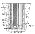
- reaction apparatus 20 is seen generally having subsurface portion 21 shown in vertical cross-section extending vertically below ground surface level 22. Above-ground portion 23 is shown schematically for simplicity. Subsurface portion 21 of reaction apparatus 20 is assembled in a subterranean shaft or well 24 which preferably extends at least approximately 1524 metres (approximately 5000 feet) below ground surface level 22. Subterranean shaft or well 24 is a conventional cylindrical well-hole drilled in the known manner.
- the walls of well 24 are lined or cased with primary well casing 25 which is secured to the walls of the well hole with a layer of grout 26.
- Grout 26 may include a thermal stabilizing agent since it is subjected to elevated temperatures during operation.
- Primary casing 25 forms a vertical, elongated encasement and defines heat-transfer media chamber 30 which in this embodiment is in the nature of a cylinder.
- Bottom or floor 31 of chamber 30 may simply comprise a grout plug or the like.
- Primary casing 25 serves to confine a heat-transfer medium during operation. It should be formed of a material which is relatively non-porous and in a manner such that no cracks or voids are present which would allow the heat-transfer medium to flow into surrounding rock formations. Suitable materials include alloyed steels. Carbon steels are preferred. Secondary casing 35 is also provided which extends only partially into the well hole adjacent primary casing 25. The upper end of primary casing 25 is secured in place with base support plate 40, preferably formed of metal, positioned at ground level to which primary casing 25 is preferably welded. In order to achieve an even lower profile for above ground portion 23, metal base plate 40 may be recessed below ground surface level 22.
- Conduit 45 defines channel 53 through which a heat-transfer medium is flowed during operation.
- conduit 45 is preferably a thermally insulating tube or insulated tubular. Both conduit 45 and reaction vessel 50 are spaced apart from primary casing 25 as best shown in Figure 2 which is a sectional view taken along lines 2-2 of Figure 1. Conduit 45 and reaction vessel 50 are also spaced above floor 31 to permit the unobstructed flow of heat-transfer medium.
- reaction vessel 50 includes waste containment pipe or tube 55 having waste pipe 60 suspended therein.
- Waste containment tube 55 and waste pipe 60 are arranged in a concentric or tube-within-a-tube relationship and are welded at one end or otherwise attached to base plate 40. It may be suitable in some applications to provide an intermediate connector (not shown) between base plate 40 and the tubes suspended therefrom to allow for the removal of the reaction tubes for maintenance purposes.
- the reaction tubes are most preferably connected to base plate 40 in such a manner as to allow for expansion and contraction of the tubes during changes in temperature which are encountered during operation of reaction apparatus 20.
- Bottom 63 of waste containment tube 55 is closed with an end cap or the like.
- waste pipe 60 The lower end of waste pipe 60 is open such that waste channel 65 which it defines is in flow communication with waste annulus 70. Waste channel 65 and waste annulus 70 are in heat exchange relation to one another. It will be apparent that waste annulus 70 lies between the outer surface of waste pipe 60 and the inner surface of waste containment tube 55. It is in reaction vessel 50 that the desired chemical reaction is brought about. As will be explained in the method of the present invention a gaseous reactant is injected into reaction vessel 50 through oxygen supply lines 75, 76, 79 and 80, shown extending into waste annulus 70 at multiple depths.
- Waste containment tube 55 is preferably formed from a corrosion resistant material such as stainless steel or a titanium alloy.
- Above ground portion 23 includes those devices which are used to operate reaction apparatus 20, including pumps, valves, storage and mixing tanks, heat exchange devices and the like.
- above ground portion 23 includes waste supply tank 85 in which diluted municipal wastes or other reactants are prepared to be introduced preferably into waste annulus 70 of reaction vessel 50 through waste flow lines 90 and 95.
- Waste pumps 100 and 105 facilitate the flow of waste into waste annulus 70.
- Waste flow is regulated with valves 110 and 115 in waste flow lines 90 and 95.
- Effluent tank 120 is also provided in flow communication with waste channel 65 via effluent flow line 122 which includes effluent pump 125 and valve 130.
- Oxygen source 135 is seen having common oxygen supply line 140 connecting oxygen supply lines 75, 76, 79 and 80.
- Oxygen source 135 may include liquid oxygen tanks, compressors, pumps and the like.
- reservoir 145 with its associated flow lines 150 and 152 are provided.
- Heat-transfer medium is stored in reservoir 145.
- Each flow line 150 and 152 includes, respectively, pumps 155 and 157 and valves 160 and 162 by which the flow of heat exchange medium is regulated.
- heater 175 Positioned in flow line 152 is heater 175 by which heat is supplied to the heat-transfer medium during operation. Heat may be removed from the heat-transfer medium with cooler 177 in flow line 150.
- upper portion 24 of reaction apparatus 20 is shown diagrammatically for simplicity and further particulars of a system of this general type are provided in US-A- 4 272 383.
- upper portion 23 may include ash settling tanks, by-pass lines, back-pressure control valves, low pressure pumps, pressure control valves, and the like.
- Reaction vessel 180 includes waste containment tube 185 and waste pipe 187 arranged concentrically in the fashion of waste containment tube 55 and waste pipe 60 to form waste annulus 188 and waste channel 189.
- waste containment tube 185 and waste pipe 187 arranged concentrically in the fashion of waste containment tube 55 and waste pipe 60 to form waste annulus 188 and waste channel 189.
- reaction vessel 50 may also be suitable to react one set of reactants in reaction vessel 50 while simultaneously reacted a different set of reactants in reaction vessel 180 with both reactions being controlled with a heat-transfer medium in chamber 30. If chamber 30 is made sufficiently large, an even greater number of reaction vessels could be employed in a single reaction apparatus 20. With multiple reaction vessels, it may be desirable in some instances to provide more than one conduit 45 for the flow of heat-transfer medium.
- reaction apparatus 20 By externalizing the heat exchange components of reaction apparatus 20 relative to reaction vessel 50, several important advantages are achieved by the present invention. Primarily, the volume of waste which can be processed in reaction vessel 50 is increased substantially since the space previously occupied by the central heat exchanger is now available to be occupied by waste. By adjusting the relative diameters of waste containment tube 55 and waste pipe 60 this newly available space can be equally portioned between waste channel 65 and waste annulus 70. Also, by providing a common chamber 30 for receiving a heat exchange medium, multiple reaction vessels 50 can be suspended in chamber 30 and controlled with a single heat exchanger as depicted in Figures 4 and 5.
- reaction vessel 50 allows the capacity of reaction vessel 50 to be increased simply by increasing the diameters of waste containment tube 55 and waste pipe 60 without increasing any other stringers as previously required. Since reaction vessel 50 now contains only a single annulus, annulus fouling by the accumulation of organic matter in the multiple annular spaces present in a reaction apparatus having a centrally disposed heat exchanger is reduced. The placement of instruments for determining pressure and temperature in reaction apparatus 20 is also facilitated by the present invention.
- the externalization of the heat-exchanger substantially increases the surface area of the heat-exchange interface of the heat-exchanger and the reaction vessel which is an important feature of the present invention.
- This substantial increase in surface area of the heat-exchanger at its interface with the reaction vessel provides better utilization of start-up energy, enhances temperature mediated control of the reaction and maximizes the efficiency of thermal energy recovery procedures using the heat-exchanger.
- the wet-oxidation processing of many municipal wastes exposes the walls of the reaction vessel to materials having high-chloride contents.
- the wet oxidation of manure which has a high concentration of chlorides, requires the use of chloride resistant materials to form the reaction vessel such that the metal surfaces in contact with the waste do not corrode easily.
- Expensive, high-grade, nickel or titanium alloys may at times be used to form the reaction vessel strings.
- the configuration of the present invention, wherein the heat-exchanger is externalized relative to the reaction vessel significantly reduces the quantity of high-grade nickel or titanium alloy needed to construct the reaction vessel, yet maintains the conventional throughput capacity of the reaction apparatus.
- the present invention at current prices of high-grade nickel and titanium alloys, it may be possible to reduce the cost of the reaction vessel by as much as fifty percent. Of course, less expensive materials may be suitable for forming the tubes of the reaction vessel in many applications. In addition, the present invention reduces drilling costs since a smaller hole may be bored to accommodate a reaction vessel of equivalent volume.
- reaction apparatus 20 is preferably used for the aqueous phase oxidation of a dilute municipal waste.
- a municipal waste containing combustible organic matter is diluted with water in waste supply tank 85 to a solids concentration of about 5 percent by weight and a chemical oxygen demand of from about 1 percent to 5 percent.
- the diluted municipal waste is then pumped through waste flow lines 90 and 95 by pumps 105 and 100 respectively to substantially fill waste annulus 70 of reaction vessel 50. This forms an annular, hydrostatic column which exerts substantial pressure at the bottom of waste containment tube 55.
- gaseous oxygen which may be in a mixture of other gases is injected into the waste from oxygen source 135 into common oxygen supply line 140 and through oxygen supply lines 75, 76, 79 and 80.
- the injection of gaseous oxygen is controlled such that intense mixing and contacting between the gaseous oxygen and the organic waste is brought about to optimize mass transfer of the reactants. It may be desirable in some applications to add heat to the diluted waste as it is pumped into waste annulus 70 using an above ground heater (not shown).
- a heat-transfer medium such as oil is flowed into heater 175 from reservoir 145.
- the heat-transfer medium is heated to an elevated temperature with heater 175 and then pumped through flow line 152 into channel 53 of conduit 45.
- the heat-transfer medium flows through channel 53 into chamber 30.
- the hot heat-transfer medium pours into the bottom of chamber 30 and, as the flow continues, the level of heat-transfer medium rises, enveloping waste containment tube 55.
- the diluted waste is oxidized rapidly and the reaction temperature is sufficiently high such that excess heat can be withdrawn.
- This can be achieved by pumping the heat-transfer medium out of chamber 30 through flow line 150 using pump 155 and regulating the flow with valve 160.
- Heat is extracted from the heat exchange medium by cooler 177. The thermal energy obtained thereby can be used for a variety of purposes, including the generation of electricity such as with a steam turbine.
- the reaction products are flowed out of the reaction zone of waste annulus 70 and are forced upwardly through waste channel 65 of waste pipe 60.
- the flow of materials through reaction vessel 50 is preferably continuous.
- the hot waste product or effluent gives off heat through waste pipe 60 to the diluted municipal waste flowing downwardly through waste annulus 70.
- the effluent is flowed through flow line 122 by pump 125, the flow rate being regulated by valve 130.
- the effluent is pumped into effluent tank 120 which as stated may include separation devices for separating the low-volume sterile ash, the liquid effluent portion and the off gases which are produced during the wet oxidation reaction. These reaction products contain many useful by-products and may receive further waste treatment.
- the preferred method of the present invention includes introducing the diluted waste into waste annulus 70 during start-up in order to maximize the transfer of heat from the heat-transfer medium to the diluted waste, it may be suitable and desirable in some applications to reverse the flow of dilute waste through reaction vessel 50 by introducing the diluted waste into waste channel 65 of waste pipe 60 during start-up. It is also to be understood that the flow of heat-transfer medium can be reversed such that it is withdrawn from chamber 30 through conduit 45.
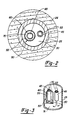
- reaction vessel 250 includes waste containment tube 255 and centrally disposed inner tube or waste pipe 260, arranged generally concentrically as in the previous embodiment.
- a third tube or outer tube or pipe portion referred to as heat exchange jacket 262 is provided which surrounds but is spaced apart from intermediate or waste containment tube 255 in a generally concentric manner.
- Heat exchange jacket 262 defines heat exchange annulus 263 which is in flow communication with chamber 230 through end 264 of heat exchange jacket 262 which is open.
- the concentricity of reaction vessel 250 is clearly illustrated.
- the method of operation of this embodiment is the same as that for the two tube reaction vessel 50 except that the level of heat-transfer medium 266 is kept at the lower portion of chamber 230 by pressurizing the upper portion of chamber 230 with an inert gas such as nitrogen or with air.
- the heat-transfer medium 266 thus flows upwardly through heat-transfer annulus 263 where it is in heat-transfer relation to the waste annulus.
- heat loss through primary casing 225 to the surrounding rock formations is substantially reduced.
- pack-off assemblies 267 are placed around heat exchange jacket 262 to form a seal with primary casing 225.
- pack-off assemblies 267 surround conduit 245 likewise forming a seal with primary casing 225.
- Pack-off assemblies 267 serve to partition chamber 30 into an upper portion 268 and a lower portion 269.
- the heat-transfer medium is flowed into lower portion 269 of chamber 230 through heat exchange media conduit 245 and, being blocked by pack-off assembly 267, is then forced upwardly through heat exchange annulus 263.
- Upper portion 268 of chamber 230 can be filled with insulating material (not shown) to better conserve thermal energy.
- Pack-off assemblies 267 should be formed of a material which can be formed into the desired shape and which is non-porous with respect to the particular heat-transfer medium which is employed.
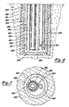
- first and second heat-transfer media conduits 272 and 274, respectively, are provided whereby hot heat exchange or heat transfer medium can be flowed into partitioned heat-transfer media chamber 276.
- Pack-off assembly 278 partially defines partitioned heat-transfer media chamber 276 and may comprise a radially extending pack-off member as shown in Figure 9.
- Reaction vessel 280 is seen suspended within the chamber defined by well casing 282 which includes partioned heat-transfer media chambers 276.
- reaction vessel 280 includes waste containment pipe or tube 284 having closed end 286 such that reactants may be confined therein.
- waste pipe 290 Centrally disposed in the bore of waste containment pipe 284 and spaced apart therefrom to define annulus 288 is waste pipe 290. End 292 of waste pipe 290 is open so that flow communication is established between annulus 288 and bore or waste channel 294.
- heat-transfer media conduits 272 and 274 conduits 272 and 274 are illustrated here as being radially secured in place by grout or cement 293.
- both heat-transfer media conduits 272 and 274 are each suspended in well casings, the well casings being rigidly secured in place by grout or the like.
- This alternative arrangement allows heat-transfer media conduits 272 and 274 to be removed conveniently from the respective well casings for cleaning or repair.
- heat transfer media conduit 274 extends downwardly adjacent well casing 282 and is connected by horizontal section 296 which is shown here simply as a transverse section of insulated tubular pipe.
- Horizontal section 296 links heat-transfer media channel 298, defined by heat-transfer conduit 274, in flow communication with partitioned heat transfer media chamber 276 at subchamber or circulation space 300.
- Circulation space 300 should be of sufficient size to allow good circulation of the heat-exchange medium below reaction vessel 280.
- heat-transfer conduit 272 is arranged such that the heat-transfer media channel 302 which it defines is connected to circulation space 300 by horizontal section 304, which is again a transverse section of insulated tubular pipe. It is preferred that this connection between horizontal section 304 and circulation space 300 be made near the top of circulation space 300. This allows for the withdrawal of hot heat-transfer medium through heat-transfer media channel 302 during the exothermic phase of a reaction. Significant heat conservation is thus achieved and the hot heat-transfer medium may be used as a source of thermal energy in surface applications.
- reaction vessel 280 in reaction apparatus 271 of Figure 9 is shown clearly in Figure 10 of the drawings which is a cross-sectional view taken along line 10-10 of Figure 9.
- heat-transfer media conduits 272 and 274 are shown secured in place by grout 293, with horizontal sections 296 and 304 shown in phantom.
- Well casing 282 is also seen secured in place, having reaction vessel 280 suspended therein.
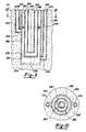
- reaction apparatus 306 which includes heat-exchange jacket 308 having pack-off assemblies 310 which make sealing contact with well casing 312.
- Subchamber 314 is thereby defined such that heat-transfer medium entering subchamber 314 is forced upwardly through open end 316 of heat-exchange jacket 308.
- Heat-exchange jacket 308 defines heat-exchange annulus 318 through which heat-exchange medium is in heat-transfer relation with reaction vessel 320 at waste containment pipe 322.
- waste tube 324 Centrally disposed in waste containment tube 322, in the manner previously described, resides waste tube 324.
- heat-transfer conduit 326 is seen secured in place by grout 327 and defines heat-transfer media channel 328 which is in flow communication with subchamber 314 by virtue of horizontal section 330.
- Heat-transfer media conduit 326 and horizontal section 330 preferably comprise sections of insulated tubular pipe.
- reaction vessel 322 is shown generally having subchamber 334 which is the lower portion of heat-transfer media chamber 336.
- Heat-transfer media chamber is again defined by well casing 338 shown grouted in place in a well hole.
- Reaction vessel 340 is suspended therein in the fashion previously described which allows for its convenient removal from heat-transfer media chamber 336.
- a portion of well casing 338 is interrupted at horizontal passage 341 which serves to provide flow communication between heat-transfer media channel 342 and heat-transfer media chamber 336.
- heat-transfer conduit 344 To allow heat-transfer conduit 344 to be conveniently removed from reaction apparatus 332 a separate well casing 346 is provided which is rigidly secured in place by grout 327 as shown in both Figures 13 and 14.
- the flow of heat-transfer medium through channel 344, across passage 341 and into heat-transfer media chamber 336 is maintained by providing packing assemblies 348 which prevent the heat-transfer medium from flowing into annulus 350.
- packing assemblies 348 By providing subchamber 334 good circulation of the heat-transfer medium through the system is obtained.
Landscapes
- Chemical & Material Sciences (AREA)
- Organic Chemistry (AREA)
- Life Sciences & Earth Sciences (AREA)
- Environmental & Geological Engineering (AREA)
- Hydrology & Water Resources (AREA)
- Engineering & Computer Science (AREA)
- Chemical Kinetics & Catalysis (AREA)
- Water Supply & Treatment (AREA)
- Biodiversity & Conservation Biology (AREA)
- Microbiology (AREA)
- Physical Or Chemical Processes And Apparatus (AREA)
- Saccharide Compounds (AREA)
- Organic Low-Molecular-Weight Compounds And Preparation Thereof (AREA)
Claims (14)
- Appareil de réaction (20) pour effectuer des réactions chimiques, comportant:(a) des moyens pour contenir un milieu d'échange de chaleur qui comprennent un tubage de puits (25) qui revêt un forage vertical souterrain (24), le tubage de puits définissant une chambre allongée (30), la chambre (30) comportant une partie supérieure et une partie inférieure,(b) un conduit allongé (45) thermiquement isolé disposé dans la chambre (30) et qui s'étend dans et s'ouvre vers la partie inférieure de la chambre allongée (30) pour amener le milieu d'échange de chaleur dans la chambre allongée (30);(c) un récipient de réaction allongé (50) disposé dans la chambre allongée (30) et distant du conduit allongé (45) thermiquement isolé, le récipient de réaction (50) comportant une première et une deuxième partie de tube (60,55) définissant un premier et un deuxième passage d'écoulement communicants, le premier et le deuxième passage d'écoulement étant en relation d'échange de chaleur l'un avec l'autre;(d) des moyens (105,100) pour introduire dans le récipient de réaction allongé (50) un fluide contenant au moins deux agents réactionnels afin de former une colonne de fluide comportant une zone réactionnelle sous une pression choisie; et(e) des moyens pour faire circuler le milieu d'échange de chaleur à travers le conduit allongé (45) thermiquement isolé et la chambre allongée (30) de façon que de la chaleur puisse être transférée entre le milieu d'échange de chaleur et les agents réactionnels dans le récipient de réaction allongé (50) afin d'obtenir et de régler une réaction chimique entre les agents réactionnels.
- Appareil de réaction selon la revendication 1, lequel comprend aussi un deuxième récipient de réaction allongé (180) disposé dans la chambre allongée (30) et distant du conduit allongé thermiquement isolé, le deuxième récipient de réaction allongé (180) comportant une première et une deuxième partie de tube (187,185) définissant un premier et un deuxième passage d'écoulement communicants, le premier et le deuxième passage d'écoulement étant en relation d'échange de chaleur l'un avec l'autre et le deuxième récipient de réaction allongé (180) étant distant du premier récipient de réaction allongé (50).
- Appareil de réaction selon la revendication 1, dans lequel la première partie de tube (60) du récipient de réaction est disposée de manière essentiellement concentrique dans la deuxième partie de tube (55) du récipient de réaction (50), la première partie de tube étant distante de la deuxième partie de tube, et dans lequel l'un d'entre le premier et le deuxième passage d'écoulement communicants est un espace annulaire (70) défini par la première et la deuxième partie de tube (60,55), la deuxième partie de tube (55) étant fermée en son extrémité inférieure (63).
- Appareil de réaction selon la revendication 1, dans lequel le récipient de réaction allongé comprend encore une troisième partie de tube (262) qui entoure la première et la deuxième partie de tube (260,255), la troisième partie de tube (262) définissant un passage en relation de transfert de chaleur avec l'un d'entre le premier et le deuxième passage d'écoulement communicants, le passage (263) défini par la troisième partie de tube étant en communication d'écoulement avec la chambre allongée (230), et dans lequel les moyens pour faire circuler le milieu d'échange de chaleur à travers le conduit allongé (245) thermiquement isolé dans la chambre allongée (230) fait aussi circuler le milieu d'échange de chaleur à travers le passage (263) défini par la troisième partie de tube.
- Appareil de réaction selon la revendication 4, lequel comprend aussi au moins un ensemble de remplissage (278) disposé dans la chambre allongée (230), l'ensemble de remplissage (267) étant en contact d'étanchéité avec le tubage de puits (225), la troisième partie de tube (262) et le conduit allongé (245) thermiquement isolé, l'ensemble de remplissage (267) formant une paroi de séparation entre la partie supérieure (268) et la partie inférieure (269).
- Appareil de réaction selon l'une quelconque des revendications 1 à 5, lequel comprend aussi une pluralité (50,180) de ces récipients de réaction allongés.
- Appareil de réaction selon l'une quelconque des revendications 1 à 6, dans lequel un réservoir (145) est prévu essentiellement au niveau de la surface du sol pour contenir le milieu d'échange de chaleur.
- Appareil de réaction selon l'une quelconque des revendications 1 à 7, dans lequel il est prévu des moyens (175) pour amener de la chaleur au milieu d'échange de chaleur.
- Appareil de réaction selon l'une quelconque des revendications 1 à 8, dans lequel il est prévu essentiellement au niveau de la surface du sol des moyens (150) pour enlever de la chaleur au milieu d'échange de chaleur.
- Appareil de réaction selon l'une quelconque des revendications 1 à 9, dans lequel il est prévu des moyens (150,175) pour régler la température du milieu d'échange de chaleur afin de régler la température des agents réactionnels.
- Appareil de réaction selon l'une quelconque des revendications 1 à 10, dans lequel il est prévu une couche de mastic (26) entre tubage de puits (25) et les parois du forage vertical souterrain (24).
- Appareil de réaction selon l'une quelconque des revendications 1 à 10, dans lequel il est prévu essentiellement au niveau de la surface du sol une plaque de base (40) à laquelle sont reliés en une de leurs extrémités les parties de tube (60,55) et le conduit isolé (45).
- Appareil de réaction selon l'une quelconque des revendications 1 à 12, dans lequel il est prévu un ensemble de remplissage (278) en contact d'étanchéité avec le tubage de puits (225), le récipient de réaction (250) et le conduit allongé (245) de telle manière que le forage vertical souterrain (24) s'en trouve divisé en parties.
- Procédé pour effectuer une réaction chimique accélérée, comportant la mise à disposition(a) de moyens pour contenir un milieu d'échange de chaleur qui comprennent un tubage de puits (25) qui revêt un forage vertical souterrain (24), le tubage de puits (25) définissant une chambre allongée (30), la chambre (30) comportant une partie supérieure et une partie inférieure,(b) un conduit allongé (45) thermiquement isolé disposé dans la chambre (30) et qui s'étend dans et s'ouvre vers la partie inférieure de la chambre allongée pour amener le milieu d'échange de chaleur dans la chambre allongée;(c) un récipient de réaction allongé (50) disposé dans la chambre allongée (30) et distant du conduit allongé (45) thermiquement isolé, le récipient de réaction (50) comportant une première et une deuxième partie de tube (60,55) définissant un premier et un deuxième passage d'écoulement communicants, le premier et le deuxième passage d'écoulement étant en relation d'échange de chaleur l'un avec l'autre;l'introduction dans le récipient de réaction allongé (50) d'un fluide contenant au moins deux agents réactionnels afin de former une colonne de fluide comportant une zone réactionnelle sous une pression choisie;
et la circulation du milieu d'échange de chaleur à travers le conduit allongé (45) thermiquement isolé et la chambre allongée (30) de façon que de la chaleur puisse être transférée entre le milieu d'échange de chaleur et les agents réactionnels dans le récipient de réaction allongé (50) afin d'obtenir et de régler une réaction chimique entre les agents réactionnels.
Priority Applications (1)
| Application Number | Priority Date | Filing Date | Title |
|---|---|---|---|
| AT88302035T ATE78008T1 (de) | 1987-03-13 | 1988-03-09 | Apparat und verfahren zur durchfuehrung chemischer reaktionen. |
Applications Claiming Priority (2)
| Application Number | Priority Date | Filing Date | Title |
|---|---|---|---|
| US07/025,470 US4803054A (en) | 1987-03-13 | 1987-03-13 | Asymmetric heat-exchange reaction apparatus for effecting chemical reactions |
| US25470 | 1987-03-13 |
Publications (2)
| Publication Number | Publication Date |
|---|---|
| EP0282276A1 EP0282276A1 (fr) | 1988-09-14 |
| EP0282276B1 true EP0282276B1 (fr) | 1992-07-08 |
Family
ID=21826249
Family Applications (1)
| Application Number | Title | Priority Date | Filing Date |
|---|---|---|---|
| EP88302035A Expired - Lifetime EP0282276B1 (fr) | 1987-03-13 | 1988-03-09 | Appareil et méthode pour effectuer des réactions chimiques |
Country Status (9)
| Country | Link |
|---|---|
| US (1) | US4803054A (fr) |
| EP (1) | EP0282276B1 (fr) |
| JP (1) | JPH0698304B2 (fr) |
| KR (1) | KR920002068B1 (fr) |
| AT (1) | ATE78008T1 (fr) |
| CA (1) | CA1306847C (fr) |
| DE (1) | DE3872549T2 (fr) |
| DK (1) | DK136188A (fr) |
| IE (1) | IE62127B1 (fr) |
Families Citing this family (38)
| Publication number | Priority date | Publication date | Assignee | Title |
|---|---|---|---|---|
| DE4427844C1 (de) * | 1994-07-28 | 1996-02-08 | Mannesmann Ag | Tiefschachtreaktor |
| DE4427843C1 (de) * | 1994-07-28 | 1996-01-18 | Mannesmann Ag | Tiefschachtreaktor |
| US5755974A (en) | 1994-08-01 | 1998-05-26 | Rpc Waste Management Services, Inc. | Method and apparatus for reacting oxidizable matter with a salt |
| US5551472A (en) | 1994-08-01 | 1996-09-03 | Rpc Waste Management Services, Inc. | Pressure reduction system and method |
| US5620606A (en) | 1994-08-01 | 1997-04-15 | Rpc Waste Management Services, Inc. | Method and apparatus for reacting oxidizable matter with particles |
| JP2639633B2 (ja) * | 1994-11-02 | 1997-08-13 | 轟産業株式会社 | 化学反応装置における熱交換面積調節式の反応熱制御機構 |
| US6017460A (en) | 1996-06-07 | 2000-01-25 | Chematur Engineering Ab | Heating and reaction system and method using recycle reactor |
| US5814292A (en) * | 1996-12-19 | 1998-09-29 | Energy Research Group | Comprehensive energy producing methods for aqueous phase oxidation |
| DE29722933U1 (de) * | 1997-12-19 | 1998-02-12 | Mannesmann AG, 40213 Düsseldorf | Tiefschachtreaktor zur kontinuierlichen Durchführung chemischer Reaktionen |
| DE29722931U1 (de) * | 1997-12-19 | 1998-02-12 | Mannesmann AG, 40213 Düsseldorf | Tiefschachtreaktor zur kontinuierlichen Durchführung chemischer Reaktionen |
| DE29722926U1 (de) * | 1997-12-19 | 1998-02-19 | Mannesmann AG, 40213 Düsseldorf | Tiefschachtreaktor zur kontinuierlichen Durchführung chemischer Reaktionen |
| SE518803C2 (sv) | 1999-09-03 | 2002-11-26 | Chematur Eng Ab | Metod och reaktionssystem med högt tryck och hög temperatur som är lämpat för superkritisk vattenoxidation |
| AUPR544601A0 (en) * | 2001-06-04 | 2001-06-28 | Exergen Pty Ltd | High pressure extraction |
| US6716360B2 (en) | 2002-04-16 | 2004-04-06 | Eau-Viron Incorporated | Method and apparatus for treating waste streams |
| WO2004083128A1 (fr) * | 2003-03-20 | 2004-09-30 | Vartech, B.V. | Appareil et procede pour effectuer l'oxydation humide de fond de puits |
| US7211194B2 (en) * | 2004-10-27 | 2007-05-01 | Eau-Viron, Inc. | Gravity pressure vessel and related apparatus and methods |
| US7608170B1 (en) * | 2005-06-10 | 2009-10-27 | Ousey John R | Method and apparatus to obtain high pressures for a continuous-flow pyrolysis reactor |
| US8080360B2 (en) * | 2005-07-22 | 2011-12-20 | Xerox Corporation | Toner preparation processes |
| US7582269B2 (en) * | 2005-09-23 | 2009-09-01 | Vertical Tube Reactor, Llc | Thermally autogenous subsurface chemical reactor and method |
| BE1017935A3 (fr) * | 2006-10-04 | 2009-12-01 | Bilteryst Pierre Jean | Procede d'exploitation de l'energie gravitationnelle terrestre. |
| BRMU8701289U2 (pt) * | 2007-07-11 | 2009-02-25 | Ivane Rodrigues De Souza | aparelho para produzir biocarvço |
| US8481800B2 (en) * | 2009-04-01 | 2013-07-09 | Earth Renewal Group, Llc | Aqueous phase oxidation process |
| US8115047B2 (en) * | 2009-04-01 | 2012-02-14 | Earth Renewal Group, Llc | Aqueous phase oxidation process |
| US7915474B2 (en) * | 2009-04-01 | 2011-03-29 | Earth Renewal Group, Llc | Aqueous phase oxidation process |
| US9272936B2 (en) | 2009-04-01 | 2016-03-01 | Earth Renewal Group, Llc | Waste treatment process |
| US7951988B2 (en) * | 2009-04-01 | 2011-05-31 | Earth Renewal Group, Llc | Aqueous phase oxidation process |
| US8168847B2 (en) * | 2009-04-01 | 2012-05-01 | Earth Renewal Group, Llc | Aqueous phase oxidation process |
| US8955591B1 (en) | 2010-05-13 | 2015-02-17 | Future Energy, Llc | Methods and systems for delivery of thermal energy |
| WO2012016192A2 (fr) * | 2010-07-30 | 2012-02-02 | Brooks Automation, Inc. | Cryopompe à haute vitesse pour réfrigérateurs multiples |
| BR112013003712A2 (pt) | 2010-08-18 | 2020-06-23 | Future Energy Llc | Método e sistema para fornecimento de energia superfície em uma formação subterrânea através de um poço vertical conectado |
| DE102010062833B3 (de) * | 2010-12-10 | 2012-06-06 | Helmholtz-Zentrum Für Umweltforschung Gmbh - Ufz | Verfahren und Reaktor zur hydrothermalen Karbonisierung von Biomassen im Tiefschacht-Reaktor und zur gleichzeitigen Nassoxidation der anfallenden Prozesswässer |
| WO2015060979A1 (fr) * | 2013-10-24 | 2015-04-30 | The Regents Of The University Of California | Bioréacteur et système de perfusion |
| CN105013409B (zh) * | 2014-04-24 | 2018-10-26 | 北京金菲特能源科技有限公司 | 一种含有井中隔热逆流式固定床反应器的系统 |
| CA3011641C (fr) * | 2016-09-09 | 2018-11-06 | Nulife Greentech Inc. | Extraction d'une fraction d'hydrocarbures liquides a partir d'une charge de depart de dechets carbones |
| GB2559583B (en) * | 2017-02-09 | 2022-04-20 | Phycofeeds Ltd | Hydrothermal liquefaction reactor |
| KR102022375B1 (ko) | 2018-08-22 | 2019-09-18 | (주)넥서스일렉트로닉스 | Uhd tv용 업스케일 칩셋 모듈 |
| US11077328B2 (en) * | 2019-10-14 | 2021-08-03 | David Stanley Moulton | Apparatus for improving vertical flow reactor utility |
| US20230257291A1 (en) * | 2022-02-15 | 2023-08-17 | Thomas J. Burke | Apparatus for continuous heat and pressure processing of a fluid |
Family Cites Families (6)
| Publication number | Priority date | Publication date | Assignee | Title |
|---|---|---|---|---|
| US3449247A (en) * | 1965-10-23 | 1969-06-10 | William J Bauer | Process for wet oxidation of combustible waste materials |
| US3606999A (en) * | 1967-08-04 | 1971-09-21 | Harold L Lawless | Method of and apparatus for carrying out a chemical or physical process |
| US3853759A (en) * | 1968-06-06 | 1974-12-10 | J Titmas | Dynamic hydraulic column activation method |
| CA1095696A (fr) * | 1976-12-22 | 1981-02-17 | Richard F. Buswell | Appareil a reaction catalytique |
| US4272383A (en) * | 1978-03-17 | 1981-06-09 | Mcgrew Jay Lininger | Method and apparatus for effecting subsurface, controlled, accelerated chemical reactions |
| DE3225287A1 (de) * | 1982-07-02 | 1984-01-05 | Schering AG, 1000 Berlin und 4709 Bergkamen | Neue carbacyclinamide, verfahren zu ihrer herstellung und ihre verwendung als arzneimittel |
-
1987
- 1987-03-13 US US07/025,470 patent/US4803054A/en not_active Expired - Lifetime
- 1987-08-05 KR KR1019870008572A patent/KR920002068B1/ko not_active Expired
-
1988
- 1988-01-21 CA CA000557004A patent/CA1306847C/fr not_active Expired - Fee Related
- 1988-02-19 JP JP63035469A patent/JPH0698304B2/ja not_active Expired - Fee Related
- 1988-03-09 AT AT88302035T patent/ATE78008T1/de not_active IP Right Cessation
- 1988-03-09 EP EP88302035A patent/EP0282276B1/fr not_active Expired - Lifetime
- 1988-03-09 DE DE8888302035T patent/DE3872549T2/de not_active Expired - Lifetime
- 1988-03-10 IE IE70388A patent/IE62127B1/en not_active IP Right Cessation
- 1988-03-11 DK DK136188A patent/DK136188A/da not_active Application Discontinuation
Also Published As
| Publication number | Publication date |
|---|---|
| JPH0698304B2 (ja) | 1994-12-07 |
| IE880703L (en) | 1988-09-13 |
| KR880011026A (ko) | 1988-10-25 |
| EP0282276A1 (fr) | 1988-09-14 |
| CA1306847C (fr) | 1992-09-01 |
| JPS63236537A (ja) | 1988-10-03 |
| DE3872549T2 (de) | 1992-12-03 |
| DK136188D0 (da) | 1988-03-11 |
| US4803054A (en) | 1989-02-07 |
| DE3872549D1 (de) | 1992-08-13 |
| DK136188A (da) | 1988-09-14 |
| KR920002068B1 (ko) | 1992-03-10 |
| IE62127B1 (en) | 1994-12-14 |
| ATE78008T1 (de) | 1992-07-15 |
Similar Documents
| Publication | Publication Date | Title |
|---|---|---|
| EP0282276B1 (fr) | Appareil et méthode pour effectuer des réactions chimiques | |
| EP0267338B1 (fr) | Echangeur de traitement des fluides | |
| JPS63100927A (ja) | 制御された化学反応を行わせる方法及び反応装置 | |
| US4272383A (en) | Method and apparatus for effecting subsurface, controlled, accelerated chemical reactions | |
| US3606999A (en) | Method of and apparatus for carrying out a chemical or physical process | |
| EP0281302B1 (fr) | Procédé pour effectuer des réactions chimiques | |
| US4774006A (en) | Fluid treatment method | |
| US4869833A (en) | Method and apparatus for controlled chemical reactions | |
| US4741386A (en) | Fluid treatment apparatus | |
| FI89772C (fi) | Foerfarande och anordning foer utfoerande av kontrollerade kemiska reaktioner | |
| EP0018366B1 (fr) | Methode et appareil pour effectuer des reactions chimiques accelerees, controllees, sous terre | |
| CA2623036C (fr) | Reacteur chimique de sous-surface thermiquement autogene et methode associee | |
| CA1249807A (fr) | Appareil de traitement de fluides, son echangeur de chaleur, et methode de faconnage d'un corps tubulaire isole | |
| FI86579B (fi) | Laongstraeckt vaermevaexlare och vaetskebehandlingsanordning. |
Legal Events
| Date | Code | Title | Description |
|---|---|---|---|
| PUAI | Public reference made under article 153(3) epc to a published international application that has entered the european phase |
Free format text: ORIGINAL CODE: 0009012 |
|
| AK | Designated contracting states |
Kind code of ref document: A1 Designated state(s): AT BE CH DE GB IT LI NL SE |
|
| 17P | Request for examination filed |
Effective date: 19890228 |
|
| 17Q | First examination report despatched |
Effective date: 19891011 |
|
| RAP1 | Party data changed (applicant data changed or rights of an application transferred) |
Owner name: WASTE TREATMENT PATENTS & RESEARCH N.V. |
|
| GRAA | (expected) grant |
Free format text: ORIGINAL CODE: 0009210 |
|
| AK | Designated contracting states |
Kind code of ref document: B1 Designated state(s): AT BE CH DE GB IT LI NL SE |
|
| REF | Corresponds to: |
Ref document number: 78008 Country of ref document: AT Date of ref document: 19920715 Kind code of ref document: T |
|
| ITF | It: translation for a ep patent filed | ||
| REF | Corresponds to: |
Ref document number: 3872549 Country of ref document: DE Date of ref document: 19920813 |
|
| PLBE | No opposition filed within time limit |
Free format text: ORIGINAL CODE: 0009261 |
|
| STAA | Information on the status of an ep patent application or granted ep patent |
Free format text: STATUS: NO OPPOSITION FILED WITHIN TIME LIMIT |
|
| 26N | No opposition filed | ||
| EAL | Se: european patent in force in sweden |
Ref document number: 88302035.6 |
|
| REG | Reference to a national code |
Ref country code: GB Ref legal event code: IF02 |
|
| PGFP | Annual fee paid to national office [announced via postgrant information from national office to epo] |
Ref country code: NL Payment date: 20060131 Year of fee payment: 19 |
|
| PGFP | Annual fee paid to national office [announced via postgrant information from national office to epo] |
Ref country code: DE Payment date: 20060302 Year of fee payment: 19 |
|
| PGFP | Annual fee paid to national office [announced via postgrant information from national office to epo] |
Ref country code: GB Payment date: 20060308 Year of fee payment: 19 |
|
| PGFP | Annual fee paid to national office [announced via postgrant information from national office to epo] |
Ref country code: AT Payment date: 20060313 Year of fee payment: 19 |
|
| PGFP | Annual fee paid to national office [announced via postgrant information from national office to epo] |
Ref country code: CH Payment date: 20060315 Year of fee payment: 19 |
|
| PGFP | Annual fee paid to national office [announced via postgrant information from national office to epo] |
Ref country code: IT Payment date: 20060331 Year of fee payment: 19 |
|
| PGFP | Annual fee paid to national office [announced via postgrant information from national office to epo] |
Ref country code: BE Payment date: 20060509 Year of fee payment: 19 |
|
| PG25 | Lapsed in a contracting state [announced via postgrant information from national office to epo] |
Ref country code: SE Free format text: LAPSE BECAUSE OF NON-PAYMENT OF DUE FEES Effective date: 20070310 |
|
| REG | Reference to a national code |
Ref country code: CH Ref legal event code: PL |
|
| EUG | Se: european patent has lapsed | ||
| PG25 | Lapsed in a contracting state [announced via postgrant information from national office to epo] |
Ref country code: AT Free format text: LAPSE BECAUSE OF NON-PAYMENT OF DUE FEES Effective date: 20070309 |
|
| GBPC | Gb: european patent ceased through non-payment of renewal fee |
Effective date: 20070309 |
|
| NLV4 | Nl: lapsed or anulled due to non-payment of the annual fee |
Effective date: 20071001 |
|
| BERE | Be: lapsed |
Owner name: *WASTE TREATMENT PATENTS & RESEARCH N.V. Effective date: 20070331 |
|
| PG25 | Lapsed in a contracting state [announced via postgrant information from national office to epo] |
Ref country code: BE Free format text: LAPSE BECAUSE OF NON-PAYMENT OF DUE FEES Effective date: 20070331 |
|
| PG25 | Lapsed in a contracting state [announced via postgrant information from national office to epo] |
Ref country code: NL Free format text: LAPSE BECAUSE OF NON-PAYMENT OF DUE FEES Effective date: 20071001 Ref country code: DE Free format text: LAPSE BECAUSE OF NON-PAYMENT OF DUE FEES Effective date: 20071002 |
|
| PGFP | Annual fee paid to national office [announced via postgrant information from national office to epo] |
Ref country code: SE Payment date: 20060306 Year of fee payment: 19 |
|
| PG25 | Lapsed in a contracting state [announced via postgrant information from national office to epo] |
Ref country code: LI Free format text: LAPSE BECAUSE OF NON-PAYMENT OF DUE FEES Effective date: 20070331 Ref country code: CH Free format text: LAPSE BECAUSE OF NON-PAYMENT OF DUE FEES Effective date: 20070331 |
|
| PG25 | Lapsed in a contracting state [announced via postgrant information from national office to epo] |
Ref country code: GB Free format text: LAPSE BECAUSE OF NON-PAYMENT OF DUE FEES Effective date: 20070309 |
|
| PG25 | Lapsed in a contracting state [announced via postgrant information from national office to epo] |
Ref country code: IT Free format text: LAPSE BECAUSE OF NON-PAYMENT OF DUE FEES Effective date: 20070309 |