EP0282406B1 - Vorrichtung, um das Ende eines in einem Rohr rotierenden beweglichen Elementes in Position zu halten, und Anwendung dieser Vorrichtung - Google Patents
Vorrichtung, um das Ende eines in einem Rohr rotierenden beweglichen Elementes in Position zu halten, und Anwendung dieser Vorrichtung Download PDFInfo
- Publication number
- EP0282406B1 EP0282406B1 EP88400540A EP88400540A EP0282406B1 EP 0282406 B1 EP0282406 B1 EP 0282406B1 EP 88400540 A EP88400540 A EP 88400540A EP 88400540 A EP88400540 A EP 88400540A EP 0282406 B1 EP0282406 B1 EP 0282406B1
- Authority
- EP
- European Patent Office
- Prior art keywords
- bearing
- tube
- arms
- forming
- shank
- Prior art date
- Legal status (The legal status is an assumption and is not a legal conclusion. Google has not performed a legal analysis and makes no representation as to the accuracy of the status listed.)
- Expired - Lifetime
Links
- 239000012530 fluid Substances 0.000 claims abstract description 14
- 239000000463 material Substances 0.000 claims abstract description 5
- 238000004140 cleaning Methods 0.000 claims description 6
- 238000005452 bending Methods 0.000 claims 3
- 230000008878 coupling Effects 0.000 claims 1
- 238000010168 coupling process Methods 0.000 claims 1
- 238000005859 coupling reaction Methods 0.000 claims 1
- 230000005489 elastic deformation Effects 0.000 claims 1
- 238000011144 upstream manufacturing Methods 0.000 description 4
- CDBYLPFSWZWCQE-UHFFFAOYSA-L Sodium Carbonate Chemical compound [Na+].[Na+].[O-]C([O-])=O CDBYLPFSWZWCQE-UHFFFAOYSA-L 0.000 description 2
- 230000000694 effects Effects 0.000 description 2
- 239000007864 aqueous solution Substances 0.000 description 1
- 239000000571 coke Substances 0.000 description 1
- 238000002788 crimping Methods 0.000 description 1
- 230000007423 decrease Effects 0.000 description 1
- 238000004821 distillation Methods 0.000 description 1
- 229930195733 hydrocarbon Natural products 0.000 description 1
- 150000002430 hydrocarbons Chemical class 0.000 description 1
- 239000007788 liquid Substances 0.000 description 1
- 238000012423 maintenance Methods 0.000 description 1
- 238000004519 manufacturing process Methods 0.000 description 1
- 229910052751 metal Inorganic materials 0.000 description 1
- 239000002184 metal Substances 0.000 description 1
- 239000000203 mixture Substances 0.000 description 1
- 239000003208 petroleum Substances 0.000 description 1
- 238000003825 pressing Methods 0.000 description 1
- 230000002265 prevention Effects 0.000 description 1
- 150000003839 salts Chemical class 0.000 description 1
- 238000007493 shaping process Methods 0.000 description 1
- 229910000029 sodium carbonate Inorganic materials 0.000 description 1
- 238000004227 thermal cracking Methods 0.000 description 1
- 238000003466 welding Methods 0.000 description 1
Images
Classifications
-
- F—MECHANICAL ENGINEERING; LIGHTING; HEATING; WEAPONS; BLASTING
- F28—HEAT EXCHANGE IN GENERAL
- F28G—CLEANING OF INTERNAL OR EXTERNAL SURFACES OF HEAT-EXCHANGE OR HEAT-TRANSFER CONDUITS, e.g. WATER TUBES OR BOILERS
- F28G3/00—Rotary appliances
- F28G3/08—Rotary appliances having coiled wire tools, i.e. basket type
Definitions
- the present invention relates to a device for holding in position one end of an element mounted to rotate in a tube.
- the invention also relates to an application of this device to the prevention of fouling and to the continuous cleaning of a conduit where a fluid circulates.
- Maintaining the position of the movable elements inside the tubes poses certain problems, however, because these elements must be freely rotated by the fluid, without significantly affecting the circulation thereof in the tubes and without causing a sharp drop in pressure.
- the present invention aims to provide a device for holding in position one end of an element mounted to move in rotation in a tube, which meets the above conditions and limits the fouling of the heat exchangers in order to improve transfers. heat.
- the invention also aims to provide such a fixing device which is inexpensive to produce and which can be easily mounted on the tube equipped with the movable element in rotation, without requiring tools or attachments such as screws and pins.
- Another object of the invention is to propose a device of this type which can be made integral simultaneously with the upstream end of the tube fitted with the movable element in rotation and with the upstream end of this movable element.
- the invention finally aims to provide such a device which can be easily adapted to tubes of different diameters.
- the subject of the invention is a device for holding in position in a tube one end of an element driven in rotation by a fouling fluid circulating in said tube and intended to prevent its fouling and to ensure its cleaning by continuous, the other end of said element being free
- this device being of the type comprising a bearing member capable of being made rigidly integral with one end of said tube, and an element mounted free in rotation relative to said bearing member and rendered integral with one end of the movable element, said device being characterized in that the bearing member is a monobloc member made of a rigid material capable of deforming elastically, this monobloc member comprising at least two branches separated by a distance such that they can be forcibly engaged in an open end of said tube to bear elastically against the internal wall of the latter, so as to make rigidly integral with said tube said member forming a bearing.
- the bearing member will, for example, substantially have the shape of a U comprising two divergent branches from the central part or base of the U, this member can be made by folding a simple metal strip.
- the bearing member may also include three or four branches, or even more, adjoining the same central part and arranged regularly with respect thereto.
- the bearing member may be made by folding from a flat star-shaped part with three or four branches, or more.
- the branches of the bearing member will generally have the form of bands but may also have the form of rods.
- the branches of the bearing member can be introduced directly into the opening of a tube by bringing them closer to each other and then allowing them to move apart by elasticity to come to bear against the internal wall of the tube from which they thus become united.
- Said branches may advantageously be extended at one of their ends by a lug of reduced transverse dimensions, which alone will be introduced into the tube, while the transverse edges of the end of these branches, on either side of said lug, will take pressing against the edge of the corresponding end of the tube, thus giving a fixed position to said member and thereby preventing its entrainment in the tube.
- the device according to the invention therefore allows the user to adapt to the local conditions of the tubes to be fitted with a mobile element.
- At least one notch can advantageously be made in said flat piece at the level of the fold line of each of the branches, in the general direction thereof. here, on either side of this fold line.
- the element mounted to rotate relative to the bearing member may be constituted, in a manner known per se, by a pin comprising a head and a rod engaged in an orifice in the central part of the bearing part, the end of said rod can be made integral by any means known in the art of the movable member associated with the tube on which is mounted the bearing member.
- the free end of said rod may, for example, be bent and cooperate with a ring-shaped end of the movable element or vice versa.
- the free end of the rod may also be hollow, so as to be able to engage the corresponding end of the mobile element therein, the associated ends being able to be made integral with one another by crimping, by welding, by a screw system or other.
- a anti-wear washer may be interposed between these members and advantageously crimped on the bearing.
- An essential advantage of the device according to the invention is therefore that it can be mounted at the end of a tube and made integral with the latter without requiring any tool or any assembly member whatsoever.
- Another advantage is to be able to produce, by adequate folding of the flat part, devices suitable for tubes of different diameters.
- the use of the device according to the invention for maintaining in position one end of a movable element, disposed inside a tube and able to be driven in rotation by a fluid circulating in it, in order to prevent fouling of this tube, proves to be very advantageous in the case of the tubes of a heat exchanger. Indeed, the ends of these tubes are usually engaged in orifices of retaining plates which close the exchanger at each of its ends and the tubes either protrude a few millimeters outside of these plates, or are welded flush with these plates. In both cases, the use of the device according to the invention is advantageous.
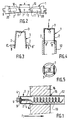
- the device shown in the drawings comprises, on the one hand, a member 1 forming a bearing, of substantially U-shaped section, the two branches 2 of which diverge from the base 3, and, on the other hand, a pin 4, comprising a head 5 and a rod 6 engaged in an opening 7 in the base 3 of the bearing 1.
- the rod 6 of the journal is disposed inside the bearing 1 between the branches 2.
- FIG. 3 shows in 8 ⁇ , in broken lines, lugs perpendicular to the branches 1 and 2, which can replace the lugs 8.
- FIG. 2 shows in broken lines, slots 20 to reduce pressure drops.
- an anti-friction washer 9 which can be free, welded or crimped. Its contact surface with the head 5 of the pin can be flat or hemispherical, depending on the profile of this head.
- the bearing 1 is in one piece and can be produced from a flat metallic piece in the form of a band, shown in FIG. 2, by folding around two lines 10.
- notches 11 may be formed on the strip 1, perpendicular to the fold lines. It will be noted that from the same flat part 1, it is possible, by making vary the spacing x of the fold lines 10, to make bearings suitable for tubes of different diameters.
- the mounting of the bearing 1 at the end of a tube 12 can be carried out by bringing the branches 2 together, to engage the lugs 8 inside the tube 12, the transverse edges of the branches 2 contiguous with the lugs 8 coming to bear against the edge of the tube 12. If these branches 2 are then released, they tend, by elasticity, to spread apart one from the other and the lugs 8 come to bear against the internal wall of the tube 12, making the bearing 1 integral with this tube, without the need to use any tool and any assembly piece that is.
- FIG. 1 illustrates the application of the device according to the invention to the maintenance in position of one end of a helical element 13, driven in rotation in a tube 12 of a heat exchanger by the fluid circulating in this tube in the direction indicated by the arrow F1, in order to prevent fouling thereof and / or to ensure its internal cleaning.
- the rod 6 of the pin 4 is hollow and the end of the tube 12 is engaged there and crimped or welded.
- the rod 6 and the end 14 of the movable element 13 could be made integral by other means known per se, for example, by using a rod whose end, bent in the manner of a hook, is engaged in a ring with which the end of the mobile element 1 is fitted, or vice versa by folding this end of the mobile element in the manner of a hook and engaging it in a ring provided at the end of the pin of the journal.
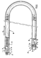
- FIG. 6 represents an implementation, in a tube 18 curved in a U, at the ends of said tube, of two devices in accordance with the invention.
- the fluid circulates in the direction indicated by the arrow F2, from the upstream end 21 of the tube 18 to the downstream end 22 of said tube.
- the lugs 8 ending the branches 2 of the bearing 1 are engaged in the tube as described in relation to Figure 1, and the head 5 of the journal, as before, is outside of the bearing 1.
- the bearing 1 has been engaged in the opposite direction in the tube, with the base 3 of this bearing arranged inside the tube, the U-shaped section of the bearing opening towards the end 22 of said tube.
- the two branches having a preferably curved profile, under the effect of the circulating fluid, bear by elasticity against the internal wall of the tube 18.
- the washer 9 is arranged in the same way as above.
- the pin 4 ⁇ is produced differently.
- the head 5 ⁇ of the journal arranged inside the tube and connected by the rod 6 ⁇ to another mobile 13 ⁇ , is extended by a rod 23 passing through the base 3 of the bearing 1. So that the journal remains trapped in the bearing, the end 24 of rod 23 is for example split beforehand so that during assembly, by separating the two lips 25 from rod, the pin remains secured to the bearing.
- the head 5 ⁇ remains constantly in contact with the internal surface of the washer 9.
Landscapes
- Engineering & Computer Science (AREA)
- Chemical & Material Sciences (AREA)
- Combustion & Propulsion (AREA)
- Mechanical Engineering (AREA)
- General Engineering & Computer Science (AREA)
- Cleaning In General (AREA)
- Supports For Pipes And Cables (AREA)
- Heat-Exchange Devices With Radiators And Conduit Assemblies (AREA)
- Investigating Or Analyzing Materials By The Use Of Ultrasonic Waves (AREA)
- Mechanical Pencils And Projecting And Retracting Systems Therefor, And Multi-System Writing Instruments (AREA)
- Quick-Acting Or Multi-Walled Pipe Joints (AREA)
- Battery Mounting, Suspending (AREA)
- Coating Apparatus (AREA)
- Toys (AREA)
- Resistance Heating (AREA)
- Investigating Or Analyzing Materials By The Use Of Magnetic Means (AREA)
- Sampling And Sample Adjustment (AREA)
- Drying Of Solid Materials (AREA)
Claims (12)
Priority Applications (1)
| Application Number | Priority Date | Filing Date | Title |
|---|---|---|---|
| AT88400540T ATE61103T1 (de) | 1987-03-13 | 1988-03-08 | Vorrichtung, um das ende eines in einem rohr rotierenden beweglichen elementes in position zu halten, und anwendung dieser vorrichtung. |
Applications Claiming Priority (2)
| Application Number | Priority Date | Filing Date | Title |
|---|---|---|---|
| FR8703462A FR2612267B1 (fr) | 1987-03-13 | 1987-03-13 | Dispositif pour le maintien en position d'une extremite d'un element monte mobile en rotation dans un tube et application de ce dispositif |
| FR8703462 | 1987-03-13 |
Publications (2)
| Publication Number | Publication Date |
|---|---|
| EP0282406A1 EP0282406A1 (de) | 1988-09-14 |
| EP0282406B1 true EP0282406B1 (de) | 1991-02-27 |
Family
ID=9348940
Family Applications (1)
| Application Number | Title | Priority Date | Filing Date |
|---|---|---|---|
| EP88400540A Expired - Lifetime EP0282406B1 (de) | 1987-03-13 | 1988-03-08 | Vorrichtung, um das Ende eines in einem Rohr rotierenden beweglichen Elementes in Position zu halten, und Anwendung dieser Vorrichtung |
Country Status (11)
| Country | Link |
|---|---|
| US (1) | US4848446A (de) |
| EP (1) | EP0282406B1 (de) |
| JP (1) | JP2533604B2 (de) |
| KR (1) | KR0124932B1 (de) |
| AT (1) | ATE61103T1 (de) |
| AU (1) | AU595690B2 (de) |
| CA (1) | CA1315499C (de) |
| DE (1) | DE3861804D1 (de) |
| ES (1) | ES2020604B3 (de) |
| FR (1) | FR2612267B1 (de) |
| GR (1) | GR3001518T3 (de) |
Families Citing this family (14)
| Publication number | Priority date | Publication date | Assignee | Title |
|---|---|---|---|---|
| FR2637659B1 (fr) * | 1988-10-10 | 1991-01-18 | Total France | Dispositif perfectionne pour le maintien en position d'une extremite d'un element monte mobile en rotation dans un tube |
| FR2639425B1 (fr) * | 1988-11-18 | 1991-06-07 | Total France | Procede et dispositif de nettoyage d'un tube dans lequel circule un fluide, et utilisation dans les tubes d'echangeurs de chaleur |
| US5043956A (en) * | 1989-06-26 | 1991-08-27 | Seiko Instruments Inc. | Wristwatch with oscillation alarm |
| BR0012365A (pt) | 1999-07-12 | 2003-07-15 | Halliburton Energy Serv Inc | Processo para o tratamento de correntes quentes/mornas de poço de hidrocarbonetos com pressão relativamente elevada, e, aparelho de tratamento para precipitar um sólido dissolvido em um óleo |
| FR2890162B1 (fr) * | 2005-08-30 | 2007-11-30 | Total France Sa | Dispositif reducteur d'encrassement d'un echangeur thermique tubulaire. |
| US9687843B2 (en) | 2007-10-23 | 2017-06-27 | Becton, Dickinson And Company | Tissue container for molecular and histology diagnostics incorporating a breakable membrane |
| FR2940152B1 (fr) | 2008-12-19 | 2011-01-21 | Total Raffinage Marketing | Dispositif pour la reduction de l'encrassement a l'interieur d'un tube |
| CN106390490B (zh) * | 2016-06-16 | 2019-01-04 | 湖南工业大学 | 一种冲动伞式自然循环蒸发器 |
| CN107875658B (zh) * | 2017-10-30 | 2019-09-10 | 俞天翔 | 波流阀自动清洗式竖管降膜蒸发器 |
| FR3094764B1 (fr) | 2019-04-05 | 2021-05-14 | Total Raffinage Chimie | Insert d’extrémité de conduit |
| FR3165010A1 (fr) | 2024-07-25 | 2026-01-30 | IFP Energies Nouvelles | Installation et procede d’hydrotraitement ou d’hydroconversion avec echangeurs de chaleur tubulaires munis d’inserts |
| FR3165061A1 (fr) | 2024-07-25 | 2026-01-30 | IFP Energies Nouvelles | Insert rotatif pour tube d’echangeur de chaleur |
| FR3165060A1 (fr) | 2024-07-25 | 2026-01-30 | IFP Energies Nouvelles | Insert rotatif pour tube d’echangeur de chaleur comportant une aide a la rotation |
| FR3165062A1 (fr) | 2024-07-25 | 2026-01-30 | IFP Energies Nouvelles | Insert pour tubes d’echangeur de chaleur diphasique |
Family Cites Families (9)
| Publication number | Priority date | Publication date | Assignee | Title |
|---|---|---|---|---|
| US4174750A (en) * | 1978-04-18 | 1979-11-20 | Nichols Billy M | Tube cleaner having anchored rotatable spiral member |
| US4583585A (en) * | 1981-07-22 | 1986-04-22 | Elf France | System for cleaning tube-type exchangers automatically during operation |
| US4564066A (en) * | 1981-07-29 | 1986-01-14 | Gorman Jeremy W | Perforate bearing plate for turbulators in heat exchangers |
| DE3327321A1 (de) * | 1983-07-29 | 1985-02-07 | Motoren-Werke Mannheim AG vorm. Benz Abt. stationärer Motorenbau, 6800 Mannheim | Vorrichtung zum reinigen des mindestens einen rohres von waermeuebertragern |
| US4641705A (en) * | 1983-08-09 | 1987-02-10 | Gorman Jeremy W | Modification for heat exchangers incorporating a helically shaped blade and pin shaped support member |
| FR2554520B1 (fr) * | 1983-11-09 | 1986-05-02 | Elf France | Dispositif de fixation rotative d'un element dans un tube |
| FR2569829B1 (fr) * | 1984-08-31 | 1989-06-16 | Raffinage Cie Francaise | Procede et dispositif mecanique destines a ameliorer les transferts thermiques et a prevenir l'encrassement des echangeurs de chaleur |
| FR2592924B1 (fr) * | 1986-01-10 | 1989-10-20 | Total France | Dispositif de maintien en position d'une extremite d'un element mobile, entraine en rotation dans un tube et application a la prevention de l'encrassement et au nettoyage de ce tube. |
| US4701245A (en) * | 1986-05-05 | 1987-10-20 | W. R. Grace & Co. | Oxidation of organic compounds using a catalyzed cerium (IV) composition |
-
1987
- 1987-03-13 FR FR8703462A patent/FR2612267B1/fr not_active Expired
-
1988
- 1988-03-08 AT AT88400540T patent/ATE61103T1/de not_active IP Right Cessation
- 1988-03-08 DE DE8888400540T patent/DE3861804D1/de not_active Expired - Lifetime
- 1988-03-08 EP EP88400540A patent/EP0282406B1/de not_active Expired - Lifetime
- 1988-03-08 ES ES88400540T patent/ES2020604B3/es not_active Expired - Lifetime
- 1988-03-11 CA CA000561280A patent/CA1315499C/fr not_active Expired - Fee Related
- 1988-03-11 AU AU13033/88A patent/AU595690B2/en not_active Ceased
- 1988-03-11 US US07/166,713 patent/US4848446A/en not_active Expired - Lifetime
- 1988-03-12 JP JP63059212A patent/JP2533604B2/ja not_active Expired - Fee Related
- 1988-03-12 KR KR1019880002666A patent/KR0124932B1/ko not_active Expired - Fee Related
-
1991
- 1991-02-28 GR GR90400997T patent/GR3001518T3/el unknown
Also Published As
| Publication number | Publication date |
|---|---|
| ATE61103T1 (de) | 1991-03-15 |
| AU1303388A (en) | 1988-09-15 |
| KR0124932B1 (ko) | 1997-12-23 |
| JP2533604B2 (ja) | 1996-09-11 |
| DE3861804D1 (de) | 1991-04-04 |
| AU595690B2 (en) | 1990-04-05 |
| KR880011951A (ko) | 1988-10-31 |
| GR3001518T3 (en) | 1992-11-23 |
| FR2612267A1 (fr) | 1988-09-16 |
| ES2020604B3 (es) | 1991-08-16 |
| US4848446A (en) | 1989-07-18 |
| EP0282406A1 (de) | 1988-09-14 |
| FR2612267B1 (fr) | 1989-07-21 |
| CA1315499C (fr) | 1993-04-06 |
| JPS63291677A (ja) | 1988-11-29 |
Similar Documents
| Publication | Publication Date | Title |
|---|---|---|
| EP0282406B1 (de) | Vorrichtung, um das Ende eines in einem Rohr rotierenden beweglichen Elementes in Position zu halten, und Anwendung dieser Vorrichtung | |
| WO2000032976A1 (fr) | Coupleur a billes | |
| EP0233092B1 (de) | Vorrichtung, um das Ende eines in einem Rohr rotierenden beweglichen Elementes in Position zu halten, und Anwendung für diese Vorrichtung | |
| WO2009033885A1 (fr) | Balai d'essuyage a projection de liquide pour vitres de vehicule | |
| EP3220034B1 (de) | Kupplungselement für die verbindung von flüssigkeitsführenden bauteilen und kupplung mit einem solchen element. | |
| FR2955651A1 (fr) | Dispositif de nettoyage de surfaces, mobile, et application particuliere pour le nettoyage des elements de refroidisseur thermique | |
| FR2760783A1 (fr) | Element d'un train de tiges de forage rotatif | |
| EP3150896A1 (de) | Schlauchklemme mit abstandhalter | |
| EP1934546B1 (de) | Vorrichtung zur reduzierung des fouling-verhaltens bei einem rohrwärmetauscher | |
| FR2583335A1 (fr) | Tete d'extrusion a filiere rotative et procede de lubrification de cette tete | |
| EP1678435B1 (de) | Führungsrohr für einen flexiblen kanal zum transport von kohlenwasserstoffen | |
| FR2967250A1 (fr) | Echangeur de chaleur avec dispositif de raccordement | |
| FR2637659A1 (fr) | Dispositif perfectionne pour le maintien en position d'une extremite d'un element monte mobile en rotation dans un tube | |
| FR2913479A1 (fr) | Joint tournant et rotor correspondant pour appareil a helices entrainees par l'ejection de gaz sous pression sur une pale et de l'helice, notamment pour helicoptere. | |
| FR2663691A3 (fr) | Structure pour relier des tuyaux. | |
| EP2015016A1 (de) | Wärmetauscher für Heizbottich | |
| FR2749919A1 (fr) | Dispositif de raccordement | |
| FR2782938A1 (fr) | Procede et dispositif de grattage de la surface externe d'elements longilignes tels des profiles | |
| FR2866409A3 (fr) | Raccord femelle pour conduite de fluide | |
| FR2681032A1 (fr) | Dispositif de chauffage d'un liquide de lave-glace, en particulier pour vehicule automobile. | |
| EP2596875B1 (de) | Rohrreinigungseinrichtung | |
| FR2734337A1 (fr) | Ensemble de flexible pour gaz, muni de raccords | |
| FR2806762A1 (fr) | Dispositif de fixation du type vis-ecrou a desserrage rapide | |
| FR3094764A1 (fr) | Insert d’extrémité de conduit | |
| FR2869088A1 (fr) | Raccord femelle pour conduite de fluide |
Legal Events
| Date | Code | Title | Description |
|---|---|---|---|
| PUAI | Public reference made under article 153(3) epc to a published international application that has entered the european phase |
Free format text: ORIGINAL CODE: 0009012 |
|
| AK | Designated contracting states |
Kind code of ref document: A1 Designated state(s): AT BE DE ES GB GR IT NL SE |
|
| 17P | Request for examination filed |
Effective date: 19890126 |
|
| 17Q | First examination report despatched |
Effective date: 19900115 |
|
| GRAA | (expected) grant |
Free format text: ORIGINAL CODE: 0009210 |
|
| AK | Designated contracting states |
Kind code of ref document: B1 Designated state(s): AT BE DE ES GB GR IT NL SE |
|
| REF | Corresponds to: |
Ref document number: 61103 Country of ref document: AT Date of ref document: 19910315 Kind code of ref document: T |
|
| ITF | It: translation for a ep patent filed | ||
| REF | Corresponds to: |
Ref document number: 3861804 Country of ref document: DE Date of ref document: 19910404 |
|
| GBT | Gb: translation of ep patent filed (gb section 77(6)(a)/1977) | ||
| PLBE | No opposition filed within time limit |
Free format text: ORIGINAL CODE: 0009261 |
|
| STAA | Information on the status of an ep patent application or granted ep patent |
Free format text: STATUS: NO OPPOSITION FILED WITHIN TIME LIMIT |
|
| 26N | No opposition filed | ||
| REG | Reference to a national code |
Ref country code: GR Ref legal event code: FG4A Free format text: 3001518 |
|
| EAL | Se: european patent in force in sweden |
Ref document number: 88400540.6 |
|
| PGFP | Annual fee paid to national office [announced via postgrant information from national office to epo] |
Ref country code: SE Payment date: 19960226 Year of fee payment: 9 |
|
| PGFP | Annual fee paid to national office [announced via postgrant information from national office to epo] |
Ref country code: AT Payment date: 19960229 Year of fee payment: 9 Ref country code: GR Payment date: 19960229 Year of fee payment: 9 |
|
| PG25 | Lapsed in a contracting state [announced via postgrant information from national office to epo] |
Ref country code: AT Effective date: 19970308 |
|
| PG25 | Lapsed in a contracting state [announced via postgrant information from national office to epo] |
Ref country code: SE Effective date: 19970309 |
|
| PG25 | Lapsed in a contracting state [announced via postgrant information from national office to epo] |
Ref country code: GR Free format text: THE PATENT HAS BEEN ANNULLED BY A DECISION OF A NATIONAL AUTHORITY Effective date: 19970930 |
|
| REG | Reference to a national code |
Ref country code: GR Ref legal event code: MM2A Free format text: 3001518 |
|
| EUG | Se: european patent has lapsed |
Ref document number: 88400540.6 |
|
| REG | Reference to a national code |
Ref country code: GB Ref legal event code: IF02 |
|
| PGFP | Annual fee paid to national office [announced via postgrant information from national office to epo] |
Ref country code: IT Payment date: 20060331 Year of fee payment: 19 |
|
| PGFP | Annual fee paid to national office [announced via postgrant information from national office to epo] |
Ref country code: NL Payment date: 20070313 Year of fee payment: 20 |
|
| PGFP | Annual fee paid to national office [announced via postgrant information from national office to epo] |
Ref country code: DE Payment date: 20070316 Year of fee payment: 20 |
|
| PGFP | Annual fee paid to national office [announced via postgrant information from national office to epo] |
Ref country code: GB Payment date: 20070322 Year of fee payment: 20 |
|
| PGFP | Annual fee paid to national office [announced via postgrant information from national office to epo] |
Ref country code: ES Payment date: 20070329 Year of fee payment: 20 |
|
| PGFP | Annual fee paid to national office [announced via postgrant information from national office to epo] |
Ref country code: BE Payment date: 20070419 Year of fee payment: 20 |
|
| BE20 | Be: patent expired |
Owner name: CIE DE RAFFINAGE ET DE DISTRIBUTION *TOTAL FRANCE Effective date: 20080308 |
|
| REG | Reference to a national code |
Ref country code: GB Ref legal event code: PE20 Expiry date: 20080307 |
|
| PG25 | Lapsed in a contracting state [announced via postgrant information from national office to epo] |
Ref country code: NL Free format text: LAPSE BECAUSE OF EXPIRATION OF PROTECTION Effective date: 20080308 |
|
| NLV7 | Nl: ceased due to reaching the maximum lifetime of a patent |
Effective date: 20080308 |
|
| PG25 | Lapsed in a contracting state [announced via postgrant information from national office to epo] |
Ref country code: GB Free format text: LAPSE BECAUSE OF EXPIRATION OF PROTECTION Effective date: 20080307 |
|
| REG | Reference to a national code |
Ref country code: ES Ref legal event code: FD2A Effective date: 20080310 |
|
| PG25 | Lapsed in a contracting state [announced via postgrant information from national office to epo] |
Ref country code: ES Free format text: LAPSE BECAUSE OF EXPIRATION OF PROTECTION Effective date: 20080310 |
|
| PG25 | Lapsed in a contracting state [announced via postgrant information from national office to epo] |
Ref country code: IT Free format text: LAPSE BECAUSE OF NON-PAYMENT OF DUE FEES Effective date: 20070308 |