EP0282411B1 - Cheville à expansion - Google Patents
Cheville à expansion Download PDFInfo
- Publication number
- EP0282411B1 EP0282411B1 EP88400547A EP88400547A EP0282411B1 EP 0282411 B1 EP0282411 B1 EP 0282411B1 EP 88400547 A EP88400547 A EP 88400547A EP 88400547 A EP88400547 A EP 88400547A EP 0282411 B1 EP0282411 B1 EP 0282411B1
- Authority
- EP
- European Patent Office
- Prior art keywords
- sleeve
- expansion
- plug
- wedge
- corner
- Prior art date
- Legal status (The legal status is an assumption and is not a legal conclusion. Google has not performed a legal analysis and makes no representation as to the accuracy of the status listed.)
- Expired - Lifetime
Links
- 239000002184 metal Substances 0.000 claims description 9
- 238000004873 anchoring Methods 0.000 description 4
- 230000015572 biosynthetic process Effects 0.000 description 4
- 230000000694 effects Effects 0.000 description 2
- 238000005096 rolling process Methods 0.000 description 2
- 238000003466 welding Methods 0.000 description 2
- 238000004026 adhesive bonding Methods 0.000 description 1
- 210000003423 ankle Anatomy 0.000 description 1
- 238000005452 bending Methods 0.000 description 1
- 239000007787 solid Substances 0.000 description 1
Images

Classifications
-
- F—MECHANICAL ENGINEERING; LIGHTING; HEATING; WEAPONS; BLASTING
- F16—ENGINEERING ELEMENTS AND UNITS; GENERAL MEASURES FOR PRODUCING AND MAINTAINING EFFECTIVE FUNCTIONING OF MACHINES OR INSTALLATIONS; THERMAL INSULATION IN GENERAL
- F16B—DEVICES FOR FASTENING OR SECURING CONSTRUCTIONAL ELEMENTS OR MACHINE PARTS TOGETHER, e.g. NAILS, BOLTS, CIRCLIPS, CLAMPS, CLIPS OR WEDGES; JOINTS OR JOINTING
- F16B13/00—Dowels or other devices fastened in walls or the like by inserting them in holes made therein for that purpose
- F16B13/12—Separate metal or non-separate or non-metal dowel sleeves fastened by inserting the screw, nail or the like
- F16B13/122—Separate metal or non-separate or non-metal dowel sleeves fastened by inserting the screw, nail or the like made from a sheet-metal blank
Definitions
- the present invention relates to an expansion plug comprising a bushing with a circular and constant internal section, having a fixing end and an expandable slotted end by which the bushing is intended to be inserted into an anchoring hole, and expansion means wedge-shaped comprising a first corner, integral with the socket, and a second corner, joined to the first corner along a fracturable zone and intended, under the action of a striking tool, to cooperate with the first corner to cause the expansion of the split end of the sleeve.
- Such a dowel is used, for example, for fixing plates for covering concrete walls.
- the present invention aims to eliminate the risk presented by the ankle of document EP-A-0188173.
- the present invention relates to a dowel of the type mentioned above, characterized in that the expansion means are arranged inside the bushing which they match the inner wall, the first corner being slightly projecting out of its split end and intended to come into abutment against the bottom of the anchoring hole.
- the sleeve and the expansion corners form a single piece obtained from a sheet metal side cut, folded and rolled.
- the dowel shown in Figures 1 and 2 comprises a socket 1 of axis 12 whose inner wall 2 has a constant circular section, from a fixing end 3 to the other expandable end 4.
- the end portion 3 is here provided with an internal thread 5 for the screwing of a fixing screw which will be discussed below.
- An external thread could just as easily have been provided on this portion 3.
- the end portion 4 is provided with slots 6, here three in number, for its expansion by spacing the legs formed between the slots.
- the pin also includes, inside the sleeve, a first corner 7, slightly projecting from the expandable end 3 of the sleeve, and a second corner 8 joined to the first along two fragile and fracturable zones 9.
- These two corners 7, 8 are of semi-tubular shape, with their respective cylindrical walls matching the inner wall 2 of the sleeve and the respective planes 10, 11 of their free longitudinal edges inclined on the axis 12 of the sleeve and in the extension of each other.
- the corner 8 is thus integral with the corner 7 which is itself, by its external edge 13, integral with the sleeve by the edge 14 of the expandable end portion.
- the anchor which has just been described was formed from a sheet metal side.
- the developed surface of the sleeve and of the two corners of the dowel have been cut from this sheet metal flank, and thus obtained a substantially rectangular part 21 - the sleeve -, a trapezoidal part 27 - the first corner -, extending the rectangular portion 21 beyond the central portion of one of its two short sides, and two other trapezoidal portions 28 ′, 28 ⁇ - the second corner -, extending laterally the trapezoidal portion 27.
- the trapezoidal part 27 actually extends a leg 31 extending between two slots 6 formed in the part 21 parallel to its long sides.
- the long sides were cut into 6 ′, 6 ⁇ , along the same length as the slots 6, to form the third slot 6 of the socket.
- the large base 33 of the trapezoidal part 27 is common to the latter and to the leg 31.
- Each lateral trapezoidal part 28 ′, 28 ⁇ corresponds substantially to half of the part 27, the outer edges of these lateral parts being parallel to the long sides of the rectangular part 21 and their inner edges extending the outer edges of the trapezoidal part 27, with each side, a common portion 9.
- the length of the long sides of the part 21 is equal to that of the socket 1, the length of its short sides, substantially at the circumference of the socket.
- the length of the trapezoidal parts is equal to that of the corners.
- the trapezoidal parts 27, 28 are folded over the rectangular part 21, around the large base 33 of the part 27. These sheet metal portions are then rolled into a cylinder with an axis parallel to the line 32 and closed along a generator coincident with the longitudinal edges of the part 21, by any suitable means such as stapling, welding. Note in Figure 4 a cutout 125 and a tongue 126 for stapling.
- An anchor hole 42 is drilled beforehand in the wall 41, of diameter corresponding to the outside diameter of the dowel.
- the sleeve is then introduced into the hole, at its end 4, and it is pushed into the hole until the wedge 7 abuts against the bottom 43 of the hole.
- a tool that is introduced into the socket by its end 3 one strikes the corner 8, which fractures the fragile areas 9 of connection between the two corners.
- the corner 8 is pushed into the socket, the latter then moving over the corner 7 along the planes 10, 11 with a corner effect. This effect causes the slots 6 to open, the legs to move apart from the expandable portion 4 of the socket, in short its expansion and therefore its anchoring in the wall of the hole 42.
- the plate 40 is then applied against the wall, and through a hole drilled in the plate, a screw 44 is screwed into the tapped part 3 of the socket to fix the plate between the wall 41 and the head 45 of the screw 44.
- the invention essentially targeted a dowel formed from a single sheet metal side, it will be noted that it is not essential, in order to preserve its one-piece nature, that the dowel of the invention be thus formed.
- the two corners can be formed apart and then fixed to the tubular element by clamping, welding or gluing.
- the corner, intended to protrude slightly from the expandable end of the sleeve, or the expandable end portion of the tubular element may advantageously be provided with a flange, a tab or a support flange.
- the rear corner can be held against an internal shoulder of the tubular element. It will be noted that, when the anchor of the invention is not formed from the same sheet, the wedge-shaped expansion elements could no longer be hollow, but solid.
Landscapes
- Engineering & Computer Science (AREA)
- General Engineering & Computer Science (AREA)
- Mechanical Engineering (AREA)
- Dowels (AREA)
- Forms Removed On Construction Sites Or Auxiliary Members Thereof (AREA)
- Joining Of Building Structures In Genera (AREA)
- Insertion Pins And Rivets (AREA)
- Piles And Underground Anchors (AREA)
Description
- La présente invention concerne une cheville à expansion comprenant une douille à section interne circulaire et constante, possédant une extrémité de fixation et une extrémité fendue expansible par laquelle la douille est destinée à être introduite dans un trou d'ancrage, et des moyens d'expansion cunéiformes comprenant un premier coin, solidaire de la douille, et un second coin, réuni au premier coin le long d'une zone fracturable et destiné, sous l'action d'un outil de frappe, à coopérer avec le premier coin pour provoquer l'expansion de l'extrémité fendue de la douille.
- Une telle cheville sert, par exemple, à la fixation de plaques de revêtement de murs en béton.
- On connaît déjà une cheville du type mentionné ci-dessus par le document EP-A-0188173. Mais avec la cheville de ce document, il y a un risque que l'élément d'expansion soit chassé à l'intérieur de la douille, vers l'axe de celle-ci, et n'assure plus sa fonction d'expansion. Les moyens d'expansion de cette cheville ne se trouvent pas à l'intérieur de la douille et il ne faut surtout pas qu'ils y soient chassés. Ils s'appuient latéralement sur les flancs de l'évidement de la douille.
- La présente invention vise à éliminer le risque présenté par la cheville du document EP-A-0188173.
- A cet effet, la présente invention concerne une cheville du type mentionné ci-dessus, caractérisée par le fait que les moyens d'expansion sont disposés à l'intérieur de la douille dont ils épousent la paroi intérieure, le premier coin étant légèrement en saillie hors de son extrémité fendue et destiné à venir en butée contre le fond du trou d'ancrage.
- Dans la forme de réalisation préférée de la cheville de l'invention, la douille et les coins d'expansion forment une seule pièce obtenue à partir d'un flanc de tôle découpé, replié et roulé.
- L'invention sera mieux comprise à l'aide de la description suivante de plusieurs formes de réalisation de la cheville de l'invention, en référence aux dessins annexés, sur lesquels:
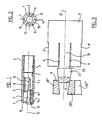
- ― la figure 1 est une vue en coupe axiale de la forme de réalisation préférée de la cheville de l'invention;
- ― la figure 2 est une vue en bout de la cheville de la figure 1;
- ― la figure 3 est une vue en plan d'un flanc de tôle découpé pour la formation par pliage et roulage de la cheville de la figure 1;
- ― la figure 4 est une vue en plan d'un autre flanc de tôle découpé pour la formation par pliage et roulage de la cheville de la figure 1, et
- ― la figure 5 est une vue en coupe axiale de la cheville de la figure 1, après ancrage et fixation à un mur d'une plaque de revêtement.
- La cheville représentée sur les figures 1 et 2, comporte une douille 1 d'axe 12 dont la paroi intérieure 2 a une section circulaire constante, depuis une extrémité de fixation 3 jusqu'à l'autre extrémité expansible 4. La portion d'extrémité 3 est ici pourvue d'un taraudage intérieur 5 pour le vissage d'un vis de fixation dont il sera question ci-après. Un filetage externe aurait tout aussi bien pu être prévu sur cette portion 3. La portion d'extrémité 4 est pourvue de fentes 6, ici au nombre de trois, pour son expansion par écartement des jambes ménagées entre les fentes. La cheville comporte aussi, à l'intérieur de la douille, un premier coin 7, légèrement en saillie hors de l'extrémité expansible 3 de la douille, et un deuxième coin 8 réuni au premier le long de deux zones fragiles et fracturables 9. Ces deux coins 7, 8 sont de forme semi-tubulaire, avec leurs parois cylindriques respectives épousant la paroi intérieure 2 de la douille et les plans respectifs 10, 11 de leurs bords libres longitudinaux inclinés sur l'axe 12 de la douille et dans le prolongement l'un de l'autre. Le coin 8 est ainsi solidaire du coin 7 qui est lui-même, par son bord externe 13, solidaire de la douille par le bord 14 de la portion d'extrémité expansible.
- La cheville qui vient d'être décrite a été formée à partir d'un flanc de tôle. En référence à la figure 3, on a découpé, dans ce flanc de tôle, la surface développée de la douille et des deux coins de la cheville, et obtenu ainsi une partie sensiblement rectangulaire 21 ― la douille ―, une partie trapézoïdale 27 ― le premier coin ―, prolongeant la portion rectangulaire 21 au-delà de la portion centrale d'un de ses deux petits côtés, et deux autres parties trapézoïdales 28′, 28˝ ― le deuxième coin ―, prolongeant latéralement la partie trapézoïdale 27.
- La partie trapézoïdale 27 prolonge en fait une jambe 31 s'étendant entre deux fentes 6 pratiquées dans la partie 21 parallèlement à ses grands côtés. Les grands côtés ont été découpés en 6′, 6˝, sur la même longueur que les fentes 6, pour former la troisième fente 6 de la douille. La grande base 33 de la partie trapézoïdale 27 est commune à celle-ci et à la jambe 31. Chaque partie trapézoïdale latérale 28′, 28˝ correspond sensiblement à la moitié de la partie 27, les bords extérieurs de ces parties latérales étant parallèles aux grands côtés de la partie rectangulaire 21 et leurs bords intérieurs prolongeant les bords extérieurs de la partie trapézoïdale 27, avec de chaque côté, une portion commune 9. La longueur des grands côtés de la partie 21 est égale à celle de la douille 1, la longueur de ses petits côtés, sensiblement à la circonférence de la douille. La longueur des parties trapézoïdales est égale à celle des coins.
- On remarquera que, au lieu de découper la partie trapézoïdale 28′, symétrique de la partie 28˝ par rapport à la ligne de symétrie 32 de l'ensemble, on pourrait tout aussi bien découper une partie trapézoïdale 28˝, 28‴ identique à la partie 27, mais retournée, la portion 28‴ de cette partie 28˝, 28‴ étant symétrique de la portion 28˝ par rapport à son bord parallèle à la ligne 32.
- De même, au lieu de découper la partie trapézoïdale centrale 27 dans le prolongement de la portion rectangulaire 21, comme sur la figure 3, on pourrait inverser la disposition de cette portion trapézoïdale centrale et des autres portions trapézoïdales latérales, pour découper les portions trapézoïdales latérales 128′, 128˝ dans le prolongement de la portion rectangulaire 121, et entre cette portion rectangulaire 121 et la portion trapézoïdale centrale 127 (figure 4). Dans ce cas, les bords latéraux de cette portion centrale 127 sont inclinés en sens inverse de celui de la portion centrale 27 de la figure 3.
- Le flanc de tôle ayant été ainsi découpé, on rabat les parties trapézoïdales 27, 28 sur la partie rectangulaire 21, autour de la grande base 33 de la partie 27. On roule ensuite ces portions de tôle en un cylindre d'axe parallèle à la ligne 32 et fermé le long d'une génératrice confondue avec les bords longitudinaux de la partie 21, par tout moyen approprié tel qu'agrafage, soudage. On remarquera sur la figure 4 une découpe 125 et une languette 126 pour l'agrafage.
- Ayant décrit la cheville de l'invention, son utilisation, ou son fonctionnement, peut maintenant être abordé, en référence à la figure 5.
- Soit donc l'objectif de fixer une plaque de revêtement 40 sur un mur en béton 41.
- On fore au préalable un trou d'ancrage 42 dans le mur 41, de diamètre correspondant au diamètre extérieur de la cheville. On introduit ensuite la douille dans le trou, par son extrémité 4, et on l'enfonce dans le trou jusqu'à ce que le coin 7 vienne en butée contre le fond 43 du trou. Puis à l'aide d'un outil qu'on introduit dans la douille par son extrémité 3, on frappe sur le coin 8, ce qui fracture les zones fragiles 9 de liaison entre les deux coins. Poursuivant la frappe, on enfonce le coin 8 dans la douille, celui-ci se déplaçant alors sur le coin 7 le long des plans 10, 11 avec un effet de coin. Cet effet provoque l'ouverture des fentes 6, l'écartement des jambes de la portion expansible 4 de la douille, bref son expansion et par conséquent son ancrage dans la paroi du trou 42.
- On applique ensuite la plaque 40 contre le mur, et à travers un orifice percé dans la plaque, on visse une vis 44 dans la partie taraudée 3 de la douille pour fixer la plaque entre le mur 41 et la tête 45 de la vis 44.
- Bien que l'invention visait essentiellement une cheville formée à partir d'un seul flanc de tôle, on notera qu'il n'est pas indispensable, pour préserver son caractère monobloc, que la cheville de l'invention soit ainsi formée. C'est ainsi que les deux coins peuvent être formés à part et fixés ensuite à l'élément tubulaire par serrage, soudage ou collage. Par ailleurs, le coin, destiné à faire légèrement saillie hors de l'extrémité expansible de la douille, ou la portion d'extrémité expansible de l'élément tubulaire, pourra avantageusement être pourvu d'un rebord, d'une patte ou d'une collerette de maintien.
- Avantageusement encore, le coin arrière pourra être maintenu contre un épaulement interne de l'élément tubulaire. On notera que, quand on ne forme pas la cheville de l'invention à partir d'une même tôle, les éléments cunéiformes d'expansion pourraient être, non plus creux, mais pleins.
- On remarquera enfin que passer du flanc de la figure 3 à celui de la figure 4 revient à inverser les coins fixe et mobile.
Claims (5)
Applications Claiming Priority (2)
| Application Number | Priority Date | Filing Date | Title |
|---|---|---|---|
| FR8703406 | 1987-03-12 | ||
| FR8703406A FR2612263B1 (fr) | 1987-03-12 | 1987-03-12 | Cheville a expansion |
Publications (2)
| Publication Number | Publication Date |
|---|---|
| EP0282411A1 EP0282411A1 (fr) | 1988-09-14 |
| EP0282411B1 true EP0282411B1 (fr) | 1991-08-07 |
Family
ID=9348901
Family Applications (1)
| Application Number | Title | Priority Date | Filing Date |
|---|---|---|---|
| EP88400547A Expired - Lifetime EP0282411B1 (fr) | 1987-03-12 | 1988-03-09 | Cheville à expansion |
Country Status (7)
| Country | Link |
|---|---|
| US (1) | US4869630A (fr) |
| EP (1) | EP0282411B1 (fr) |
| JP (1) | JPS63280904A (fr) |
| AU (1) | AU602061B2 (fr) |
| DE (1) | DE3864042D1 (fr) |
| ES (1) | ES2025788T3 (fr) |
| FR (1) | FR2612263B1 (fr) |
Families Citing this family (6)
| Publication number | Priority date | Publication date | Assignee | Title |
|---|---|---|---|---|
| EP0396805A1 (fr) * | 1989-05-11 | 1990-11-14 | Siemens Aktiengesellschaft | Cheville et outil d'ancrage dans le forage d'une plaque ou d'une paroi |
| FR2708057B1 (fr) * | 1993-07-02 | 1995-09-15 | Ferrier Christian | Cheville de fixation à expansion interne issue d'un matériau en feuille et son procédé de fabrication. |
| DE19730843A1 (de) * | 1997-07-18 | 1999-01-21 | Hilti Ag | Spreizdübel |
| DE102007039947A1 (de) * | 2007-06-20 | 2009-03-12 | Fischerwerke Gmbh & Co. Kg | Spreizbare Dübelhülse |
| US10300566B2 (en) * | 2017-07-12 | 2019-05-28 | Richard Brantley | Method and apparatus for precision alignment and tack welding of weld-neck pipe fittings to pipe |
| CN111561495B (zh) * | 2020-05-27 | 2021-10-26 | 广东电网有限责任公司东莞供电局 | 一种电力紧固件安装设备 |
Citations (1)
| Publication number | Priority date | Publication date | Assignee | Title |
|---|---|---|---|---|
| DE3444988A1 (de) * | 1984-12-10 | 1986-06-12 | Hilti Ag, Schaan | Radial aufweitbarer duebel |
Family Cites Families (9)
| Publication number | Priority date | Publication date | Assignee | Title |
|---|---|---|---|---|
| US1821401A (en) * | 1928-11-18 | 1931-09-01 | Ralph S Peirce | Attaching device |
| CH577638A5 (fr) * | 1974-06-05 | 1976-07-15 | Tuflex Ag | |
| DE3121198A1 (de) * | 1981-05-27 | 1982-12-23 | Hilti AG, 9494 Schaan | Spreizduebel |
| DE3334754A1 (de) * | 1983-09-26 | 1985-06-27 | Hilti Ag, Schaan | Spreizduebel mit keilfoermigem spreizelement |
| GB8332505D0 (en) * | 1983-12-06 | 1984-01-11 | Oxford Magnet Tech | Imaging using resonance of nuclei |
| DE3425237A1 (de) * | 1984-07-09 | 1986-02-06 | Hilti Ag, Schaan | Spreizduebel |
| DE3445963A1 (de) * | 1984-12-17 | 1986-06-26 | Hilti Ag, Schaan | Spreizduebel mit spreizhuelse und keilfoermigem spreizelement |
| DE3446158A1 (de) * | 1984-12-18 | 1986-06-26 | Hilti Ag, Schaan | Spreizduebel mit huelsenfoermigem spreizkoerper |
| DE3527092A1 (de) * | 1985-07-29 | 1987-01-29 | Hilti Ag | Ankerhuelse |
-
1987
- 1987-03-12 FR FR8703406A patent/FR2612263B1/fr not_active Expired
-
1988
- 1988-03-09 EP EP88400547A patent/EP0282411B1/fr not_active Expired - Lifetime
- 1988-03-09 DE DE8888400547T patent/DE3864042D1/de not_active Expired - Lifetime
- 1988-03-09 ES ES198888400547T patent/ES2025788T3/es not_active Expired - Lifetime
- 1988-03-10 AU AU12887/88A patent/AU602061B2/en not_active Ceased
- 1988-03-11 JP JP63056502A patent/JPS63280904A/ja active Pending
- 1988-03-11 US US07/167,219 patent/US4869630A/en not_active Expired - Fee Related
Patent Citations (1)
| Publication number | Priority date | Publication date | Assignee | Title |
|---|---|---|---|---|
| DE3444988A1 (de) * | 1984-12-10 | 1986-06-12 | Hilti Ag, Schaan | Radial aufweitbarer duebel |
Also Published As
| Publication number | Publication date |
|---|---|
| DE3864042D1 (de) | 1991-09-12 |
| FR2612263B1 (fr) | 1989-06-09 |
| ES2025788T3 (es) | 1992-04-01 |
| US4869630A (en) | 1989-09-26 |
| AU1288788A (en) | 1988-09-15 |
| FR2612263A1 (fr) | 1988-09-16 |
| AU602061B2 (en) | 1990-09-27 |
| JPS63280904A (ja) | 1988-11-17 |
| EP0282411A1 (fr) | 1988-09-14 |
Similar Documents
| Publication | Publication Date | Title |
|---|---|---|
| EP0332496B1 (fr) | Cheville à expansion par cône | |
| EP1367266B1 (fr) | Cheville à douille expansible avec une portion compressible | |
| FR2532015A1 (fr) | Dispositif d'attache a ecrou d'ancrage | |
| EP0367672B1 (fr) | Cheville pour trou d'ancrage à contre-dépouille | |
| FR2657925A1 (fr) | Dispositif de fixation sur panneau de type sandwich. | |
| EP1211430A2 (fr) | Cheville à douille expansible avec une portion compressible | |
| FR2617918A1 (fr) | Attache de fixation sur mur en pierres seches | |
| EP0282411A1 (fr) | Cheville à expansion | |
| EP0280625A1 (fr) | Cheville de suspension à fil replié | |
| FR2566479A1 (fr) | Boulon d'ancrage a manchon expansible | |
| EP0263769A1 (fr) | Paumelle à blocage axial de la broche pour porte ou fenêtre | |
| FR2817930A1 (fr) | Boulon d'ancrage a expansion pour une fixation dans un support, en particulier dans du beton | |
| CH666952A5 (fr) | Porte-lampe miniature. | |
| FR2684145A1 (fr) | Douille tubulaire de cheville a noyau d'expansion. | |
| FR2766905A1 (fr) | Profile a rainure(s) pour la mise en place d'au moins un accessoire | |
| FR2716243A1 (fr) | Insert destiné à être rapport et fixé au travers d'un élément. | |
| FR2534987A1 (fr) | Cheville expansible | |
| EP1231422A1 (fr) | Procédé pour rendre une vis imperdable, collier de fixation de tuyauteries et utilisation du procédé pour fabriquer les colliers | |
| EP0327437B1 (fr) | Cheville à expansion pour double maçonnerie | |
| FR2651701A1 (fr) | Procede de fabrication de plaques de tole a bords plies et a nervures. | |
| FR2764920A1 (fr) | Noeud d'assemblage pour echafaudages tubulaires ou analogues, quelle que soit l'utilisation de ces echafaudages | |
| FR2505420A1 (fr) | Dispositif demontable de plusieurs tubes concourants de meme section au moyen d'un raccord interieur a branches expansibles | |
| EP0866229B1 (fr) | Cheville d'ancrage, flan prédécoupé et procédé pour la réalisation de la cheville d'ancrage | |
| FR2930606A1 (fr) | Dispositif de raccordement d'elements tubulaires | |
| FR2594736A3 (fr) | Levier pour dispositifs tendeurs, notamment a leviers a genouillere |
Legal Events
| Date | Code | Title | Description |
|---|---|---|---|
| PUAI | Public reference made under article 153(3) epc to a published international application that has entered the european phase |
Free format text: ORIGINAL CODE: 0009012 |
|
| AK | Designated contracting states |
Kind code of ref document: A1 Designated state(s): BE DE ES FR GB IT NL SE |
|
| 17P | Request for examination filed |
Effective date: 19890309 |
|
| 17Q | First examination report despatched |
Effective date: 19890929 |
|
| GRAA | (expected) grant |
Free format text: ORIGINAL CODE: 0009210 |
|
| AK | Designated contracting states |
Kind code of ref document: B1 Designated state(s): BE DE ES FR GB IT NL SE |
|
| REF | Corresponds to: |
Ref document number: 3864042 Country of ref document: DE Date of ref document: 19910912 |
|
| ITF | It: translation for a ep patent filed | ||
| GBT | Gb: translation of ep patent filed (gb section 77(6)(a)/1977) | ||
| PGFP | Annual fee paid to national office [announced via postgrant information from national office to epo] |
Ref country code: NL Payment date: 19920331 Year of fee payment: 5 |
|
| REG | Reference to a national code |
Ref country code: ES Ref legal event code: FG2A Ref document number: 2025788 Country of ref document: ES Kind code of ref document: T3 |
|
| PGFP | Annual fee paid to national office [announced via postgrant information from national office to epo] |
Ref country code: ES Payment date: 19920430 Year of fee payment: 5 |
|
| PLBE | No opposition filed within time limit |
Free format text: ORIGINAL CODE: 0009261 |
|
| STAA | Information on the status of an ep patent application or granted ep patent |
Free format text: STATUS: NO OPPOSITION FILED WITHIN TIME LIMIT |
|
| 26N | No opposition filed | ||
| PGFP | Annual fee paid to national office [announced via postgrant information from national office to epo] |
Ref country code: SE Payment date: 19930215 Year of fee payment: 6 |
|
| PGFP | Annual fee paid to national office [announced via postgrant information from national office to epo] |
Ref country code: GB Payment date: 19930226 Year of fee payment: 6 |
|
| PG25 | Lapsed in a contracting state [announced via postgrant information from national office to epo] |
Ref country code: ES Free format text: LAPSE BECAUSE OF NON-PAYMENT OF DUE FEES Effective date: 19930310 |
|
| PGFP | Annual fee paid to national office [announced via postgrant information from national office to epo] |
Ref country code: BE Payment date: 19930319 Year of fee payment: 6 |
|
| PG25 | Lapsed in a contracting state [announced via postgrant information from national office to epo] |
Ref country code: NL Effective date: 19931001 |
|
| NLV4 | Nl: lapsed or anulled due to non-payment of the annual fee | ||
| PG25 | Lapsed in a contracting state [announced via postgrant information from national office to epo] |
Ref country code: GB Effective date: 19940309 |
|
| PG25 | Lapsed in a contracting state [announced via postgrant information from national office to epo] |
Ref country code: SE Free format text: LAPSE BECAUSE OF NON-PAYMENT OF DUE FEES Effective date: 19940310 |
|
| PG25 | Lapsed in a contracting state [announced via postgrant information from national office to epo] |
Ref country code: BE Effective date: 19940331 |
|
| BERE | Be: lapsed |
Owner name: SOC. DE PROSPECTION ET D'INVENTIONS TECHNIQUES SP Effective date: 19940331 |
|
| GBPC | Gb: european patent ceased through non-payment of renewal fee |
Effective date: 19940309 |
|
| EUG | Se: european patent has lapsed |
Ref document number: 88400547.1 Effective date: 19941010 |
|
| REG | Reference to a national code |
Ref country code: ES Ref legal event code: FD2A Effective date: 19990201 |
|
| PGFP | Annual fee paid to national office [announced via postgrant information from national office to epo] |
Ref country code: FR Payment date: 20020221 Year of fee payment: 15 |
|
| PGFP | Annual fee paid to national office [announced via postgrant information from national office to epo] |
Ref country code: DE Payment date: 20020320 Year of fee payment: 15 |
|
| PG25 | Lapsed in a contracting state [announced via postgrant information from national office to epo] |
Ref country code: DE Free format text: LAPSE BECAUSE OF NON-PAYMENT OF DUE FEES Effective date: 20031001 |
|
| PG25 | Lapsed in a contracting state [announced via postgrant information from national office to epo] |
Ref country code: FR Free format text: LAPSE BECAUSE OF NON-PAYMENT OF DUE FEES Effective date: 20031127 |
|
| REG | Reference to a national code |
Ref country code: FR Ref legal event code: ST |
|
| PG25 | Lapsed in a contracting state [announced via postgrant information from national office to epo] |
Ref country code: IT Free format text: LAPSE BECAUSE OF NON-PAYMENT OF DUE FEES;WARNING: LAPSES OF ITALIAN PATENTS WITH EFFECTIVE DATE BEFORE 2007 MAY HAVE OCCURRED AT ANY TIME BEFORE 2007. THE CORRECT EFFECTIVE DATE MAY BE DIFFERENT FROM THE ONE RECORDED. Effective date: 20050309 |