EP0282442B1 - Fahrgestell für Transportfahrzeuge - Google Patents
Fahrgestell für Transportfahrzeuge Download PDFInfo
- Publication number
- EP0282442B1 EP0282442B1 EP88730059A EP88730059A EP0282442B1 EP 0282442 B1 EP0282442 B1 EP 0282442B1 EP 88730059 A EP88730059 A EP 88730059A EP 88730059 A EP88730059 A EP 88730059A EP 0282442 B1 EP0282442 B1 EP 0282442B1
- Authority
- EP
- European Patent Office
- Prior art keywords
- vehicle
- axle
- air
- trailers
- designed
- Prior art date
- Legal status (The legal status is an assumption and is not a legal conclusion. Google has not performed a legal analysis and makes no representation as to the accuracy of the status listed.)
- Expired - Lifetime
Links
Images


Classifications
-
- B—PERFORMING OPERATIONS; TRANSPORTING
- B62—LAND VEHICLES FOR TRAVELLING OTHERWISE THAN ON RAILS
- B62D—MOTOR VEHICLES; TRAILERS
- B62D53/00—Tractor-trailer combinations; Road trains
- B62D53/04—Tractor-trailer combinations; Road trains comprising a vehicle carrying an essential part of the other vehicle's load by having supporting means for the front or rear part of the other vehicle
- B62D53/06—Semi-trailers
-
- B—PERFORMING OPERATIONS; TRANSPORTING
- B60—VEHICLES IN GENERAL
- B60G—VEHICLE SUSPENSION ARRANGEMENTS
- B60G17/00—Resilient suspensions having means for adjusting the spring or vibration-damper characteristics, for regulating the distance between a supporting surface and a sprung part of vehicle or for locking suspension during use to meet varying vehicular or surface conditions, e.g. due to speed or load
- B60G17/02—Spring characteristics, e.g. mechanical springs and mechanical adjusting means
- B60G17/04—Spring characteristics, e.g. mechanical springs and mechanical adjusting means fluid spring characteristics
- B60G17/052—Pneumatic spring characteristics
-
- B—PERFORMING OPERATIONS; TRANSPORTING
- B62—LAND VEHICLES FOR TRAVELLING OTHERWISE THAN ON RAILS
- B62D—MOTOR VEHICLES; TRAILERS
- B62D13/00—Steering specially adapted for trailers
- B62D13/02—Steering specially adapted for trailers for centrally-pivoted axles
Definitions
- the invention relates to a chassis according to the preamble of claim 1.
- Transport vehicles especially supply and disposal transport vehicles, must be fully manoeuvrable and manoeuvrable both on roads and off-road, for example on unpaved construction sites. This is the only way to safely carry out all transport tasks, in particular delivery and removal, both of silos and containers, especially disposal containers.
- DE-A-3523745 describes a semitrailer comprising a tractor and a semitrailer which can be connected to the tractor via a fifth wheel, the at least one longitudinal axis which can be steered by means of a steering drive and a control device for the Steering drive has.
- a locking device is provided for the steering axle.
- a control device for the steering drive can be actuated arbitrarily by a control switch provided in the driver's cab of the tractor.
- This design of the tractor-trailer is intended to ensure turning and moving in a confined space.
- the invention has for its object to design such chassis for transport vehicles such that full driving and maneuverability can be achieved with the vehicles both off-road and on paved roads and in particular on unpaved construction sites.
- At least one of the vehicle axles is advantageously designed as a lifting axle, which enables adaptation to the load and / or at least one of the vehicle axles can advantageously be displaced in the longitudinal direction of the transport vehicle, as a result of which the axle pressure can be adjusted.
- the axle pressure can be adjusted.
- full maneuverability and maneuverability is achieved both off-road and on paved roads, especially on unpaved construction sites.
- the maneuverability of the vehicle is adapted to given conditions.
- the axles mounted on the fifth wheel are pushed over the axis of rotation of the turntable. This ensures that overrun control is ensured even when reversing.
- Air-sprung vehicles have air pressure control valves on the sprung axle, the control elements of which can be adjusted by means of a rocker arm. This is connected to the vehicle via an adjusting element. The adjusting element is set and locked by the vehicle manufacturer.
- the setting member is advantageously an air pressure-controlled actuating cylinder provided with a return spring. With this actuating cylinder, the rocker can be brought into predetermined end positions, so that predetermined control states on the air pressure control valve and thus predetermined loads on the air spring can take place.
- FIGS. 1 and 2 show schematically the separate free steering and lifting of vehicle axles.
- this term also includes axle assemblies.
- a vehicle axle 38 with its wheels 39 is shown schematically in FIG.
- This vehicle axle 38 is mounted on a turntable 40 at a distance 42 from its pivot point 41.
- a steering cylinder 43 is shown schematically for steering the vehicle axle 38.
- a groove formed on the turntable 40 is shown schematically, into which a locking means 46 can engage with a wedge 47 in order to lock the steering in the straight-ahead position.
- One of the vehicle axles can be designed to be liftable with its wheels in order to be brought out of the driving position shown in FIG. 2 into the stroke position shown at 44 'and 45'. Furthermore, the possibility of an axial displacement of the vehicle axis 38 in the longitudinal direction of the vehicle is illustrated in FIG.
- the steering axles can be lifted.
- the steering and lifting axles are arranged according to the desired conditions.
- the arrangement of steering axles enables maneuverability even in confined spaces. In particular, the picking up and taking off of loads such as containers, silos, containers or the like at predetermined locations is made considerably easier.
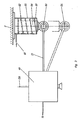
- a control valve 49 is shown schematically, which is mounted on an air-sprung axle.
- This control valve 49 controls the pressure in an air suspension. Compressed air is supplied at 58. This compressed air is supplied to the air suspension 50 in a manner controlled by the control valve 49. So far, it has been customary to determine an operating point of the control valve 49 in that the control member of the control valve 49 is connected to an adjusting member 52 via a rocker 51.
- This setting member 52 is set by the vehicle manufacturer and locked in the set position.
- This setting member 52 is designed as an actuating cylinder 55, which is connected to an air pressure control line 59.
- a piston 56 which is acted upon by a return spring 57, is arranged in this actuating cylinder 55.
- the rocker 51 can be brought into the two positions shown at 53 and 54.
- Different control characteristics of the control valve 49 can thus be set.
- the design of the air suspension according to the invention makes it possible, on the one hand, to limit the entire height of the transport vehicle during transport on a level road to the legally permissible maximum size, or, on the other hand, to adjust the ground clearance required for uneven construction site terrain, if the axle has to be balanced.
Landscapes
- Engineering & Computer Science (AREA)
- Mechanical Engineering (AREA)
- Chemical & Material Sciences (AREA)
- Combustion & Propulsion (AREA)
- Transportation (AREA)
- Vehicle Body Suspensions (AREA)
- Body Structure For Vehicles (AREA)
- Steering-Linkage Mechanisms And Four-Wheel Steering (AREA)
Description
- Die Erfindung betrifft ein Fahrgestell nach dem Oberbegriff des Patentanspruchs 1.
- Transportfahrzeuge, insbesondere Ver- und Entsorgungstransportfahrzeuge müssen sowohl auf Straßen als auch im Gelände, zum Beispiel auf unbefestigten Baustellen, voll fahr- und manövrierfähig sein. Nur so können alle Transportaufgaben, insbesondere die Zulieferung und der Abtransport, sowohl von Silos als auch von Containern, insbesondere Entsorgungscontainern sicher durchgeführt werden.
- Die DE-A-3523745 beschreibt einen Sattelzug, bestehend aus einer Zugmaschine und einem über eine Sattelkupplung mit der Zugmaschine verbindbaren Sattelanhänger der wenigstens eine mittels eines Lenktriebes lenkverstellbare Längsachse und eine Steuereinrichtung für den Lenktrieb aufweist. Bei diesem Sattelzug ist für die Lenkachse eine Verriegelungsvorrichtung vorgesehen. Bei gelöster Verriegelungsvorrichtung ist eine Steuereinrichtung für den Lenktrieb durch einen im Führerhaus der Zugmaschine vorgesehenen Steuersschalter willkürlich betätigbar. Durch diese Ausbildung des Sattelzuges soll ein Wenden und Versetzen auf engem Raum sichergestellt werden.
- Aus der DE-A-2049748 ist eine nachlaufgelenkte Achse für ein Fahrgestell eines Transportfahrzeuges bekannt.
- Der Erfindung liegt die Aufgabe zugrunde, derartige Fahrgestelle für Transportfahrzeuge derart zu gestalten, daß mit den Fahrzeugen sowohl im Gelände als auch auf befestigten Straßen und insbesondere auf unbefestigten Baustellen eine volle Fahr- und Manövrierfähigkeit erzielt werden kann.
- Erfindungsgemäß wird diese Aufgabe durch die technische Lehre des Patentanspruchs 1 gelöst.
- Mit Vorteil ist wenigstens eine der Fahrzeugachsen als Liftachse ausgebildet, wodurch eine Anpassung an die Last ermöglicht wird und/oder wenigstens eine der Fahrzeugachsen mit Vorteil in Längsrichtung des Transportfahrzeuges verschiebbar ist, wodurch eine Einstellung des Achsdrucks möglich ist. Durch eine Anpassung an die Last und eine Einstellung des Achsdruckes wird sowohl im Gelände als auch auf befestigten Straßen insbesondere auf unbefestigten Baustellen eine volle Fahr- und Manövrierfähigkeit erzielt. Durch die Verschiebung einer lenkbaren Achse wird die Manövrierfähigkeit des Fahrzeuges an gegebene Bedingungen angepaßt. Insbesondere können die drehschemelgelagerten Achsen über die Drehachse des Drehschemels geschoben werden. Dadurch wird auch bei Rückwärtsfahrt eine Nachlaufsteuerung gewährleistet.
- Bei den betrachteten, luftgefederten Fahrzeugen ist es für viele Einsatzfälle erforderlich, die Luftfederung derart zu gestalten, daß sowohl eine niedrige Fahrhöhe bei kleinem Achsausgleich als auch eine Geländetauglichkeit bei großem Achsausgleich erreicht werden kann. Luftgefederte Fahrzeuge weisen Luftdrucksteuerventile an der abgefederten Achse auf, deren Steuerelemente mittels einer Schwinge einstellbar sind. Diese ist über ein Einstellglied mit dem Fahrzeug verbunden. Das Einstellglied wird vom Fahrzeughersteller eingestellt und arretiert.
- Mit Vorteil ist das Einstellglied ein mit einer Rückholfeder versehener, luftdruckgesteuerter Stellzylinder. Mit diesem Stellzylinder kann die Schwinge in vorbestimmte Endlagen gebracht werden, so daß vorbestimmte Steuerzustände am Luftdrucksteuerventil und damit vorbestimmte Beaufschlagungen der Luftfeder erfolgen können.
- Ausführungsbeispiele der Erfindung sollen in der folgenden Beschreibung unter Bezugnahme auf die Figuren der Zeichnung erläutert werden.
- Es zeigen:
- Figur 1
- eine schematische Darstellung einer lenkbaren Achse,
- Figur 2
- eine schematische Darstellung von Achsanordnungen,
- Figur 3
- eine Prinzipskizze einer Luftfedersteuerung.
- Die Figuren 1 und 2 zeigen schematisch die gesonderte freie Lenkung und das Liften von Fahrzeugachsen. Wenn in der vorliegenden Anmeldung von einer Achse die Rede ist, umfaßt dieser Begriff auch Achsaggregate. In Figur 1 ist schematisch eine Fahrzeugachse 38 mit ihren Rädern 39 dargestellt. Diese Fahrzeugachse 38 ist an einem Drehschemel 40 im Abstand 42 von dessen Drehpunkt 41 montiert. Dadurch wird die Fahrzeugachse 38 durch Straßenreibung nachlaufgelenkt. Für die Lenkung der Fahrzeugachse 38 ist schematisch ein Lenkzylinder 43 gezeigt. Bei 48 ist schematisch eine am Drehschemel 40 ausgebildete Nut dargestellt, in die eine Arretierung 46 mit einem Keil 47 eingreifen kann, um die Lenkung in der Geradeauslaufstellung zu arretieren.
- Eine der Fahrzeugachsen kann mit ihren Rädern liftbar ausgebildet sein, um aus der in Figur 2 dargestellten Fahrstellung, in die bei 44′ und 45′ gezeigte Hublage, gebracht zu werden. Weiterhin ist in Figur 2 die Möglichkeit einer achsialen Verschiebung der Fahrzeugachse 38 in Längsrichtung des Fahrzeuges veranschaulicht.
- Die Lenkachsen können liftbar sein. Die Anordnung der Lenk- und Liftachsen wird, den gewünschten Bedingungen entsprechend, vorgenommen. Durch die Anordnung von Lenkachsen wird eine Manövrierfähigkeit auch auf engem Raum ermöglicht. Insbesondere wird das Auf- und Abnehmen von Lasten, wie Behälter, Silos, Container oder ähnliches an vorbestimmten Stellen wesentlich erleichtert.
- In Figur 3 ist ein Steuerventil 49 schematisch dargestellt, das an einer luftgefederten Achse montiert ist. Dieses Steuerventil 49 steuert den Druck in einer Luftfederung. Bei 58 wird Druckluft zugeführt. Diese Druckluft wird in vom Steuerventil 49 gesteuerter Weise der Luftfederung 50 zugeführt. Bisher war es üblich, einen Betriebspunkt des Steuerventils 49 dadurch festzulegen, daß das Steuerglied des Steuerventils 49 über eine Schwinge 51 mit einem Einstellglied 52 verbunden ist. Dieses Einstellglied 52 wird vom Fahrzeughersteller eingestellt und in der eingestellten Lage arretiert. Dieses Einstellglied 52 ist als Stellzylinder 55 ausgebildet, der mit einer Luftdrucksteuerleitung 59 in Verbindung steht. In diesem Stellzylinder 55 ist ein, mittels einer Rückholfeder 57 beaufschlagter Kolben 56 angeordnet. Mittels dieses Stellzylinders 55 kann beispielsweise die Schwinge 51 in die beiden, bei 53 und 54 dargestellten Eindstellung, gebracht werden. Damit können unterschiedliche Steuercharakteristika des Steuerventils 49 eingestellt werden. Durch die erfindungsgemäße Ausbildung der Luftfederung wird es einerseits möglich, die gesamte Höhe des Transportfahrzeuges beim Transport auf ebener Straße auf das gesetzlich zulässige Höchstmaß zu beschränken oder andererseits, bei erforderlichem Achsausgleich, die für unebenes Baustellengelände notwendige Bodenfreiheit, einzustellen.
Claims (2)
Priority Applications (1)
| Application Number | Priority Date | Filing Date | Title |
|---|---|---|---|
| AT88730059T ATE68145T1 (de) | 1987-03-10 | 1988-03-10 | Fahrgestell fuer transportfahrzeuge. |
Applications Claiming Priority (6)
| Application Number | Priority Date | Filing Date | Title |
|---|---|---|---|
| DE3707975 | 1987-03-10 | ||
| DE3707975 | 1987-03-10 | ||
| DE3716347 | 1987-05-13 | ||
| DE3716347 | 1987-05-13 | ||
| DE19873718532 DE3718532A1 (de) | 1987-03-10 | 1987-05-29 | Sattelzug mit einem lenkbaren auflieger, ggf. fuer normalen strassenverkehr |
| DE3718532 | 1987-05-29 |
Publications (3)
| Publication Number | Publication Date |
|---|---|
| EP0282442A2 EP0282442A2 (de) | 1988-09-14 |
| EP0282442A3 EP0282442A3 (en) | 1989-03-29 |
| EP0282442B1 true EP0282442B1 (de) | 1991-10-09 |
Family
ID=27195590
Family Applications (1)
| Application Number | Title | Priority Date | Filing Date |
|---|---|---|---|
| EP88730059A Expired - Lifetime EP0282442B1 (de) | 1987-03-10 | 1988-03-10 | Fahrgestell für Transportfahrzeuge |
Country Status (3)
| Country | Link |
|---|---|
| EP (1) | EP0282442B1 (de) |
| AT (1) | ATE68145T1 (de) |
| DE (1) | DE3865325D1 (de) |
Family Cites Families (4)
| Publication number | Priority date | Publication date | Assignee | Title |
|---|---|---|---|---|
| DE6751093U (de) * | 1968-08-23 | 1969-01-23 | Roman Franz Sauer | Selbstlenkende achse fuer ein strassenfahrzeug |
| US3572676A (en) * | 1968-12-23 | 1971-03-30 | Gen Motors Corp | Fluid spring incorporating fluid medium conserving flow control means |
| GB2137940A (en) * | 1983-04-14 | 1984-10-17 | Geoffrey Ronald Waterton | Container Trailer |
| AT388537B (de) * | 1984-07-16 | 1989-07-25 | Schwarzmueller Wilhelm Gmbh | Sattelzug |
-
1988
- 1988-03-10 AT AT88730059T patent/ATE68145T1/de not_active IP Right Cessation
- 1988-03-10 EP EP88730059A patent/EP0282442B1/de not_active Expired - Lifetime
- 1988-03-10 DE DE8888730059T patent/DE3865325D1/de not_active Expired - Fee Related
Also Published As
| Publication number | Publication date |
|---|---|
| EP0282442A3 (en) | 1989-03-29 |
| EP0282442A2 (de) | 1988-09-14 |
| ATE68145T1 (de) | 1991-10-15 |
| DE3865325D1 (de) | 1991-11-14 |
Similar Documents
| Publication | Publication Date | Title |
|---|---|---|
| DE102009011606A1 (de) | Vorrichtung und Verfahren zum Durchführen einer Radstandregelung für Nutzfahrzeuge | |
| DE69301343T2 (de) | Selbstlenkende Achse | |
| DE102017212127A1 (de) | Achsbaugruppe für ein Schwerlastfahrzeug und Schwerlastfahrzeug mit wenigstens einer derartigen Achsbaugruppe | |
| WO2020025201A1 (de) | Gespann mit einer sattelzugmaschine und einem auflieger, sattelzugmaschine, auflieger und verfahren zur achslastverteilung bei einem gespann | |
| EP0529544B1 (de) | Sattelzug mit motorisch angetriebener Abstützvorrichtung | |
| EP0186886B1 (de) | Sattelzug | |
| DE2546485A1 (de) | Strassenfahrzeug mit absenkbarer ladeflaeche | |
| EP0332037A2 (de) | Achsanhebevorrichtung | |
| DE69014648T2 (de) | Zugmaschine. | |
| DE4134501A1 (de) | Lastwagen, insbesondere sattelauflieger | |
| EP0313962A1 (de) | Lenkachse | |
| DE10031024A1 (de) | Kombinationstransportzug zum Transport von Lang-oder Kurzmaterial | |
| DE3523745A1 (de) | Sattelzug | |
| WO1989001435A1 (fr) | Vehicule special avec direction et cabine du conducteur pouvant etre abaissee | |
| EP0286576B1 (de) | Transportfahrzeug | |
| DE3741754A1 (de) | Schwerlasttransportfahrzeug | |
| DE4119014A1 (de) | Transportfahrzeug zum transport von raumzellen, wie stahlbeton-fertiggaragen | |
| DE19635462A1 (de) | 11lfskraftlenkung für Kraftfahrzeuge | |
| DE112022004489T5 (de) | Steuervorrichtung und Verfahren zur Steuerung eines Nachlaufachsenlenksystems | |
| DE3234475C2 (de) | ||
| EP0208825A1 (de) | Sattelzug | |
| DE102021207439A1 (de) | System und Verfahren zum Lenken eines an eine Sattelkupplung angekuppelten Anhängers | |
| EP0282442A2 (de) | Fahrgestell für Transportfahrzeuge | |
| DE19702457A1 (de) | Trägerfahrzeug | |
| DE69002443T2 (de) | Selbstlenkende Achsen für landwirtschaftliche Fahrzeuge, Strassenfahrzeuge, Baumaschinen und gleichartige Fahrzeuge. |
Legal Events
| Date | Code | Title | Description |
|---|---|---|---|
| PUAI | Public reference made under article 153(3) epc to a published international application that has entered the european phase |
Free format text: ORIGINAL CODE: 0009012 |
|
| AK | Designated contracting states |
Kind code of ref document: A2 Designated state(s): AT BE DE FR GB IT NL SE |
|
| PUAL | Search report despatched |
Free format text: ORIGINAL CODE: 0009013 |
|
| AK | Designated contracting states |
Kind code of ref document: A3 Designated state(s): AT BE DE FR GB IT NL SE |
|
| 17P | Request for examination filed |
Effective date: 19890920 |
|
| 17Q | First examination report despatched |
Effective date: 19901003 |
|
| GRAA | (expected) grant |
Free format text: ORIGINAL CODE: 0009210 |
|
| AK | Designated contracting states |
Kind code of ref document: B1 Designated state(s): AT BE DE FR GB IT NL SE |
|
| PG25 | Lapsed in a contracting state [announced via postgrant information from national office to epo] |
Ref country code: IT Free format text: LAPSE BECAUSE OF FAILURE TO SUBMIT A TRANSLATION OF THE DESCRIPTION OR TO PAY THE FEE WITHIN THE PRE;WARNING: LAPSES OF ITALIAN PATENTS WITH EFFECTIVE DATE BEFORE 2007 MAY HAVE OCCURRED AT ANY TIME BEFORE 2007. THE CORRECT EFFECTIVE DATE MAY BE DIFFERENT FROM THE ONE RECORDED.SCRIBED TIME-LIMIT Effective date: 19911009 Ref country code: GB Effective date: 19911009 Ref country code: BE Effective date: 19911009 Ref country code: SE Effective date: 19911009 |
|
| REF | Corresponds to: |
Ref document number: 68145 Country of ref document: AT Date of ref document: 19911015 Kind code of ref document: T |
|
| REF | Corresponds to: |
Ref document number: 3865325 Country of ref document: DE Date of ref document: 19911114 |
|
| EN | Fr: translation not filed | ||
| PG25 | Lapsed in a contracting state [announced via postgrant information from national office to epo] |
Ref country code: FR Effective date: 19920228 |
|
| PG25 | Lapsed in a contracting state [announced via postgrant information from national office to epo] |
Ref country code: AT Effective date: 19920310 |
|
| GBV | Gb: ep patent (uk) treated as always having been void in accordance with gb section 77(7)/1977 [no translation filed] | ||
| PLBE | No opposition filed within time limit |
Free format text: ORIGINAL CODE: 0009261 |
|
| STAA | Information on the status of an ep patent application or granted ep patent |
Free format text: STATUS: NO OPPOSITION FILED WITHIN TIME LIMIT |
|
| 26N | No opposition filed | ||
| REG | Reference to a national code |
Ref country code: FR Ref legal event code: ST |
|
| PGFP | Annual fee paid to national office [announced via postgrant information from national office to epo] |
Ref country code: NL Payment date: 19940331 Year of fee payment: 7 |
|
| PG25 | Lapsed in a contracting state [announced via postgrant information from national office to epo] |
Ref country code: NL Effective date: 19951001 |
|
| NLV4 | Nl: lapsed or anulled due to non-payment of the annual fee |
Effective date: 19951001 |
|
| PGFP | Annual fee paid to national office [announced via postgrant information from national office to epo] |
Ref country code: DE Payment date: 19980924 Year of fee payment: 11 |
|
| PG25 | Lapsed in a contracting state [announced via postgrant information from national office to epo] |
Ref country code: DE Free format text: LAPSE BECAUSE OF NON-PAYMENT OF DUE FEES Effective date: 20000101 |