EP0282465A2 - Machine à laver de taille réduite avec capacité de charge inchangée - Google Patents
Machine à laver de taille réduite avec capacité de charge inchangée Download PDFInfo
- Publication number
- EP0282465A2 EP0282465A2 EP88830094A EP88830094A EP0282465A2 EP 0282465 A2 EP0282465 A2 EP 0282465A2 EP 88830094 A EP88830094 A EP 88830094A EP 88830094 A EP88830094 A EP 88830094A EP 0282465 A2 EP0282465 A2 EP 0282465A2
- Authority
- EP
- European Patent Office
- Prior art keywords
- machine
- washing
- door
- machine according
- drum
- Prior art date
- Legal status (The legal status is an assumption and is not a legal conclusion. Google has not performed a legal analysis and makes no representation as to the accuracy of the status listed.)
- Withdrawn
Links
Images

Classifications
-
- D—TEXTILES; PAPER
- D06—TREATMENT OF TEXTILES OR THE LIKE; LAUNDERING; FLEXIBLE MATERIALS NOT OTHERWISE PROVIDED FOR
- D06F—LAUNDERING, DRYING, IRONING, PRESSING OR FOLDING TEXTILE ARTICLES
- D06F37/00—Details specific to washing machines covered by groups D06F21/00 - D06F25/00
- D06F37/26—Casings; Tubs
- D06F37/267—Tubs specially adapted for mounting thereto components or devices not provided for in preceding subgroups
-
- D—TEXTILES; PAPER
- D06—TREATMENT OF TEXTILES OR THE LIKE; LAUNDERING; FLEXIBLE MATERIALS NOT OTHERWISE PROVIDED FOR
- D06F—LAUNDERING, DRYING, IRONING, PRESSING OR FOLDING TEXTILE ARTICLES
- D06F37/00—Details specific to washing machines covered by groups D06F21/00 - D06F25/00
- D06F37/26—Casings; Tubs
- D06F37/28—Doors; Security means therefor
-
- D—TEXTILES; PAPER
- D06—TREATMENT OF TEXTILES OR THE LIKE; LAUNDERING; FLEXIBLE MATERIALS NOT OTHERWISE PROVIDED FOR
- D06F—LAUNDERING, DRYING, IRONING, PRESSING OR FOLDING TEXTILE ARTICLES
- D06F39/00—Details of washing machines not specific to a single type of machines covered by groups D06F9/00 - D06F27/00
- D06F39/12—Casings; Tubs
Definitions
- the present invention relates to a washing-machine of reduced size, especially in width, with an unchanged load capacity in comparison with the conventional machines.
- washing-machines some of these have been produced recently which, in spite of having a width limited to only 40-45 cm., show however washing performances and a load capacity totally corresponding to the traditional values, as they can efficiently wash at least 5 Kg. of dry laundry, like the machines on sale, having a standard width of 60 cm.
- the washing-machines of this type with reduced dimensions and unchanged load capacity, are exclusively provided to be loaded from the top. It is true that sometimes washing-machines of the top-loading type are convenient, but it should be appreciated that these machines cannot be provided for a built-in construction, i.e. are unsuitable to be recessed in a forniture system having an uninterrupted top plane, just due to the fact of being chargeable only from above.
- a further object of the invention is that of providing a washing-machine the main components of which may be used both for a front side and a top loading type by means of the same moulds, by adopting only simple modifications from one type to the other. Furthermore the machine of the invention can be manufactured either as free-standing household appliance or as a built-in model by merely providing in this latter case, with reference to the front side loading machine, the equipments required for the possibility of being integrated in a continuous, modular assembly.
- a washing-machine having a cylindrical washing tank and a rotary drum mounted on a shaft for rotating co-axially within said tank as it is moved by a driving motor through a pulley that is co-axial with the said drum, characterized by the rotation axis of the drum extending itself between two end bearings mounted to the side walls of the tank and being parallel to the front vertical wall of the machine, the inlet door to the machine inside being provided on said wall or on the top for a possible loading from above, there being also provided an associate opening, formed at the peripheral skirt of the tank, as well as an opening suitable to be closed at the periphery of the rotary drum.
- the washing-machine of the invention will have therefore a maximum overall width which can be of 40-45 cm, with tank and drum of standard dimensions and, according to a preferred embodiment, the front loading door is hinged along its lower side, with a retainer being provided to stop the same when open at a horizontal position.
- the machine of the invention has the filter sloping upwardly so as to have its outlet at a front wall position without interference with the lower band which, in "built-in” embodiments, comprises a baseboard to be adjusted in the depth direction.
- a first great advantage is apparent from the foregoing, deriving from the possibility of an optimal exploitation of the available width space which is required by the drum supports, as they are now comprised of a bearing at each drum side, at the closest distance possible therefrom and directly mounted to the associate side wall of the wall.
- the shaft was necessarily cantilevered at only on side, i.e. the rear side, by means of two bearings in series, which must be spaced apart by such a length to give a supporting arm long enough to produce vibrations as small as possible.
- Such an arrangement clearly required more room in the depth direction, with also the addition of the space occupied by the traditional glass door with rubber gaskets.
- the required 57 cm in the depth direction are instead obtained without problems from the width size of the traditional washing-machines, which was just of this size order, up to 60 cm, especially when using a front side loading door with reduced overall size according to the preferred embodiment of the invention.
- a further consequence of the above-mentioned arrangement of the support bearings of the rotating drum is the advantage that the gap between the latter and the washing tank may be of a reduced size radially with respect to the known machines, due to the lower capability of bending of the drum shaft, thus requiring a less quantity of water for washing, with consequent reduced consumption of detergent and electric power.
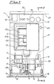
- the washing-machine of the invention comprises within a mantle or casing 1 the known components of this type of machine, i.e. a washing tank 2 containing therein a rotary perforated drum 3, having the usual size for standard load capacity of at least 5 Kg of dry laundry. It is rotatably mounted about an axis X-X, being fixed to a pulley 4 which is co-axial with the drum 3 and the tank 2 and driven in turn by a motor 6 through a belt 5.
- the washing tank is supported in a known manner by damping feet 7 and thereunder a discharge conduit 8 leads to a filter 9 through a discharge pump 9a.
- the filter is preferably directed upward slantwise, so as to open to the outside, where a filter cover 11 is provided over a base board 10, which in the model to be embedded can be adjusted in the depth direction to prevent any interference therewith.
- a discharge hose 11a conveys to the outside the water used for washing.
- casing 1 is mounted on a supporting base 15 with adjustable feet 16 resting on the floor and a control panel 12 is also provided with the various knobs and lights of control and signalling, in particular the programmer knob 13, possibly of the "push-pull" type, being the subject of a prior patent of the same applicant.
- a door 14 for the detergent-container drawer At one side of said panel, in a known position, there is also provided a door 14 for the detergent-container drawer.
- the washing-machine according to the invention has the rotation axis X-X of drum 3 directed along the width direction of the machine itself, thereby parallel to the front wall 17 thereof.
- Fig. 3 there is shown more clearly how the drum 3 is rotatably mounted about axis X-X, namely on bearings 20, 20 ⁇ on either side of the drum which preferably has at its axial zone a recess 29, 29 ⁇ on each side in order to further reduce the width overall size.
- bearing 20 has been sectioned in Fig. 3 to show the connection with the driving pulley 4 through out the thank 2 wall.
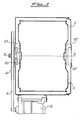
- the rotary drum 3 is formed with an inlet door 21 on its cylindrical lateral surface, e.g. comprised, as shown, of two wings 21a, 21b which are hinged at one end and can be closed by a hook means 22.
- the door 21 has been represented closed and, with broken lines, open in a position facing a front loading door 19.
- the latter is preferably made, as shown in the drawings, hinged at its lower end to the front wall 17 and provided with a stop means so as to take, when open, the horizontal position shown by broken lines in Fig. 2, which allows the utilization of a handy support plane for the laundry to be loaded into the washing-machine or when taking off the washed clothes therefrom.
- the door 19 has also the least overall size possible in the depth direction, in order to reduce as much as possible the room required without obviously any interference with the washing tank 2.
- the latter shows an opening of its lateral cylindrical surface, corresponding to the aperture defined by door 19 in the front wall 17.
- this machine is adapted to be manufactured in various models, e.g. as a top-loading type, in this case the loading door 18 will be provided on the top 23 of the machine and correspondingly the washing tank 2 will have the above-mentioned opening in its upper portion instead of the front central zone as in case of front side loading.
- Fig. 2a a portion of machine has been represented as a top loading model, and in this case it will necessarily be of the "free-standing" type, even possibly recessed between adjacent pieces of forniture, but certainly not to be integrally built-in.
- wing also covers the control panel 12, leaving clear the programmer knob 13 in case this is of the push-pull type, as already stated above it is however convenient that in association with these controls signalling lights 26 are provided, of the LED type, to indicate the operating conditions to the outside, even with closed wing.
- An upper shelf 27 with a front board being adjustable as to the height ensures the continuity of the "top” with the possibility of reaching the standard height of 85 cm for the built-in model.
Landscapes
- Engineering & Computer Science (AREA)
- Textile Engineering (AREA)
- Main Body Construction Of Washing Machines And Laundry Dryers (AREA)
Applications Claiming Priority (2)
| Application Number | Priority Date | Filing Date | Title |
|---|---|---|---|
| IT8719637A IT1216905B (it) | 1987-03-10 | 1987-03-10 | Lavabiancheria di dimensioni ridotte e capatica' di carico invariata. |
| IT1963787 | 1987-03-10 |
Publications (2)
| Publication Number | Publication Date |
|---|---|
| EP0282465A2 true EP0282465A2 (fr) | 1988-09-14 |
| EP0282465A3 EP0282465A3 (fr) | 1988-10-26 |
Family
ID=11159960
Family Applications (1)
| Application Number | Title | Priority Date | Filing Date |
|---|---|---|---|
| EP88830094A Withdrawn EP0282465A3 (fr) | 1987-03-10 | 1988-03-09 | Machine à laver de taille réduite avec capacité de charge inchangée |
Country Status (3)
| Country | Link |
|---|---|
| EP (1) | EP0282465A3 (fr) |
| AU (1) | AU613017B2 (fr) |
| IT (1) | IT1216905B (fr) |
Cited By (3)
| Publication number | Priority date | Publication date | Assignee | Title |
|---|---|---|---|---|
| EP0406115A1 (fr) * | 1989-06-30 | 1991-01-02 | Esswein S.A. | Lave-linge à ouverture frontale |
| WO2000052248A1 (fr) * | 1999-03-03 | 2000-09-08 | Rica Cuesta Jose Ignacio | Lave-linge etroit a chargement frontal |
| CN108457054A (zh) * | 2017-11-20 | 2018-08-28 | 无锡小天鹅股份有限公司 | 衣物处理装置的箱体组件、固定件和衣物处理装置 |
Family Cites Families (5)
| Publication number | Priority date | Publication date | Assignee | Title |
|---|---|---|---|---|
| DE1760602A1 (de) * | 1968-06-08 | 1971-12-16 | Cordes Wilh Maschf | Haushalts-Waschvollautomat mit einer Wasch- und Schleudertrommel,deren Drehachse parallel zur Bedienungsseite verlaeuft |
| FR2028727B3 (fr) * | 1969-01-20 | 1975-12-26 | Candy Spa | |
| FR2352095A1 (fr) * | 1976-05-21 | 1977-12-16 | Thomson Brandt | Machine a secher le linge |
| FR2478689A1 (fr) * | 1980-03-24 | 1981-09-25 | Mayc Sa | Dispositif de securite pour une porte de tambour rotatif pour une machine a laver le linge |
| IT1155278B (it) * | 1982-02-08 | 1987-01-28 | Smeg Elettrodomestici | Macchina lavabiancheria integrabile in un complesso di mobili |
-
1987
- 1987-03-10 IT IT8719637A patent/IT1216905B/it active
-
1988
- 1988-03-09 AU AU12819/88A patent/AU613017B2/en not_active Ceased
- 1988-03-09 EP EP88830094A patent/EP0282465A3/fr not_active Withdrawn
Cited By (6)
| Publication number | Priority date | Publication date | Assignee | Title |
|---|---|---|---|---|
| EP0406115A1 (fr) * | 1989-06-30 | 1991-01-02 | Esswein S.A. | Lave-linge à ouverture frontale |
| FR2649133A1 (fr) * | 1989-06-30 | 1991-01-04 | Esswein Sa | Lave-linge a ouverture frontale |
| WO2000052248A1 (fr) * | 1999-03-03 | 2000-09-08 | Rica Cuesta Jose Ignacio | Lave-linge etroit a chargement frontal |
| ES2155376A1 (es) * | 1999-03-03 | 2001-05-01 | Cuesta Jose Ignacio Rica | Lavadora estrecha de carga frontal. |
| CN108457054A (zh) * | 2017-11-20 | 2018-08-28 | 无锡小天鹅股份有限公司 | 衣物处理装置的箱体组件、固定件和衣物处理装置 |
| CN108457054B (zh) * | 2017-11-20 | 2023-08-18 | 无锡小天鹅电器有限公司 | 衣物处理装置的箱体组件、固定件和衣物处理装置 |
Also Published As
| Publication number | Publication date |
|---|---|
| EP0282465A3 (fr) | 1988-10-26 |
| AU1281988A (en) | 1988-09-08 |
| IT8719637A0 (it) | 1987-03-10 |
| AU613017B2 (en) | 1991-07-25 |
| IT1216905B (it) | 1990-03-14 |
Similar Documents
| Publication | Publication Date | Title |
|---|---|---|
| KR102647313B1 (ko) | 세탁기 | |
| RU2771266C1 (ru) | Устройство для стирки и обработки белья | |
| EP1747316B1 (fr) | Ensemble tambour pour lave-linge | |
| US7338141B2 (en) | Control panel assembly for washing machine | |
| US6981395B2 (en) | Drum type washing machine | |
| JP2009506797A (ja) | ドラム洗濯機及びこれに適用されるドラムの製造方法 | |
| KR20230018501A (ko) | 적층식 의류 처리장치 | |
| US20090007602A1 (en) | Laundry machine | |
| US7293436B2 (en) | Water supply assembly of washing machine | |
| KR102632054B1 (ko) | 세탁기 | |
| EP0282465A2 (fr) | Machine à laver de taille réduite avec capacité de charge inchangée | |
| US4972687A (en) | Washer/dryer configuration | |
| CA2170678A1 (fr) | Dispositif d'arrimage pour le transport d'electromenagers | |
| WO1999045188A1 (fr) | Ameliorations apportees a la fabrication de l'habillage d'une machine a laver | |
| KR102421544B1 (ko) | 세탁기 | |
| EP0400466B1 (fr) | Enveloppe pour appareil ménager, en particulier pour machine à laver | |
| KR100271172B1 (ko) | 드럼세탁기의 도어 | |
| CN224092198U (zh) | 一种洗衣机 | |
| KR100298816B1 (ko) | 전자동 세탁기 | |
| EP4101968A1 (fr) | Boîte de distribution pour appareil combiné lave-linge et sèche-linge | |
| CA2197749C (fr) | Bac a laver integre et structure pour meuble | |
| KR101166190B1 (ko) | 세탁기의 급수 벨로우즈 | |
| KR200277171Y1 (ko) | 세탁기의 수평 조절장치 | |
| KR20240168811A (ko) | 필터장치 및 의류 처리 장치 | |
| KR20250107671A (ko) | 의류 처리 장치 |
Legal Events
| Date | Code | Title | Description |
|---|---|---|---|
| PUAI | Public reference made under article 153(3) epc to a published international application that has entered the european phase |
Free format text: ORIGINAL CODE: 0009012 |
|
| PUAL | Search report despatched |
Free format text: ORIGINAL CODE: 0009013 |
|
| AK | Designated contracting states |
Kind code of ref document: A2 Designated state(s): DE ES FR GB SE |
|
| AK | Designated contracting states |
Kind code of ref document: A3 Designated state(s): DE ES FR GB SE |
|
| 17P | Request for examination filed |
Effective date: 19890321 |
|
| 17Q | First examination report despatched |
Effective date: 19900917 |
|
| STAA | Information on the status of an ep patent application or granted ep patent |
Free format text: STATUS: THE APPLICATION IS DEEMED TO BE WITHDRAWN |
|
| 18D | Application deemed to be withdrawn |
Effective date: 19910625 |