EP0282543B1 - Aircrew restraint systems - Google Patents
Aircrew restraint systems Download PDFInfo
- Publication number
- EP0282543B1 EP0282543B1 EP87906091A EP87906091A EP0282543B1 EP 0282543 B1 EP0282543 B1 EP 0282543B1 EP 87906091 A EP87906091 A EP 87906091A EP 87906091 A EP87906091 A EP 87906091A EP 0282543 B1 EP0282543 B1 EP 0282543B1
- Authority
- EP
- European Patent Office
- Prior art keywords
- pilot
- head
- support
- tension
- aircraft
- Prior art date
- Legal status (The legal status is an assumption and is not a legal conclusion. Google has not performed a legal analysis and makes no representation as to the accuracy of the status listed.)
- Expired
Links
- 230000000452 restraining effect Effects 0.000 claims abstract description 4
- 230000000063 preceeding effect Effects 0.000 claims 1
- 210000003128 head Anatomy 0.000 description 112
- 208000027418 Wounds and injury Diseases 0.000 description 6
- 238000013461 design Methods 0.000 description 6
- 230000000694 effects Effects 0.000 description 6
- 230000002093 peripheral effect Effects 0.000 description 6
- 230000008901 benefit Effects 0.000 description 5
- 238000010586 diagram Methods 0.000 description 5
- 230000015654 memory Effects 0.000 description 4
- 208000012661 Dyskinesia Diseases 0.000 description 3
- 208000015592 Involuntary movements Diseases 0.000 description 3
- 230000007246 mechanism Effects 0.000 description 3
- 230000017311 musculoskeletal movement, spinal reflex action Effects 0.000 description 3
- 230000003287 optical effect Effects 0.000 description 3
- 230000004044 response Effects 0.000 description 3
- 208000028373 Neck injury Diseases 0.000 description 2
- 230000009471 action Effects 0.000 description 2
- 238000012544 monitoring process Methods 0.000 description 2
- 230000021542 voluntary musculoskeletal movement Effects 0.000 description 2
- 208000020339 Spinal injury Diseases 0.000 description 1
- 208000003443 Unconsciousness Diseases 0.000 description 1
- 230000003321 amplification Effects 0.000 description 1
- 238000005452 bending Methods 0.000 description 1
- 230000008859 change Effects 0.000 description 1
- 238000004891 communication Methods 0.000 description 1
- 230000003750 conditioning effect Effects 0.000 description 1
- 230000001186 cumulative effect Effects 0.000 description 1
- 230000006378 damage Effects 0.000 description 1
- 230000003247 decreasing effect Effects 0.000 description 1
- 230000001419 dependent effect Effects 0.000 description 1
- 238000002474 experimental method Methods 0.000 description 1
- 238000001914 filtration Methods 0.000 description 1
- 210000001061 forehead Anatomy 0.000 description 1
- 230000005484 gravity Effects 0.000 description 1
- 230000004886 head movement Effects 0.000 description 1
- 230000000977 initiatory effect Effects 0.000 description 1
- 208000014674 injury Diseases 0.000 description 1
- 239000003562 lightweight material Substances 0.000 description 1
- 238000000034 method Methods 0.000 description 1
- 238000003199 nucleic acid amplification method Methods 0.000 description 1
- 230000008092 positive effect Effects 0.000 description 1
- 230000008569 process Effects 0.000 description 1
- 238000000926 separation method Methods 0.000 description 1
- 210000001154 skull base Anatomy 0.000 description 1
- 239000007787 solid Substances 0.000 description 1
- 239000000126 substance Substances 0.000 description 1
- 238000013519 translation Methods 0.000 description 1
Images




Classifications
-
- A—HUMAN NECESSITIES
- A42—HEADWEAR
- A42B—HATS; HEAD COVERINGS
- A42B3/00—Helmets; Helmet covers ; Other protective head coverings
- A42B3/04—Parts, details or accessories of helmets
- A42B3/0406—Accessories for helmets
- A42B3/0473—Neck restraints
-
- B—PERFORMING OPERATIONS; TRANSPORTING
- B64—AIRCRAFT; AVIATION; COSMONAUTICS
- B64D—EQUIPMENT FOR FITTING IN OR TO AIRCRAFT; FLIGHT SUITS; PARACHUTES; ARRANGEMENT OR MOUNTING OF POWER PLANTS OR PROPULSION TRANSMISSIONS IN AIRCRAFT
- B64D25/00—Emergency apparatus or devices, not otherwise provided for
- B64D25/02—Supports or holding means for living bodies
Definitions
- This invention relates to aircrew restraint systems and in particular to a head support and restraint system for a pilot of a high speed combat aircraft which is expected to encounter high gravitational (g) forces as it manoeuvres during flight and especially during combat.
- a problem encountered during the high speed manoeuvring of an aircraft is the effect of g-forces on the performance of the pilot.
- g-forces When large g-forces are exerted on the pilot's head and body they cause involuntary movements which can have serious consequences particularly during the critical moments of a manoeuvre.
- the pilot of an aircraft in a tight high speed turn, perhaps pursuing another aircraft can experience his head being forced downwards by a g-force several times greater than the force of gravity at the very moment when he needs to look directly ahead or upwards.
- the use of accessories such as night sights which bolt onto a pilots helmet increase the weight of and accentuate the effects of these g-forces on his head.
- Head restraints such as the one described by Rockwell in GB-A-2163 943A which corresponds to the features of the preamble of claim 1 are known which restrain the lateral movement of a pilot's head during the moments of a high speed manoeuvre while allowing the pilot to move around freely during more usual flight conditions.
- the Rockwell patent discloses an arrangement in which a pilot's head is laterally restrained by means of cables attached to his helmet and ejector seat. During ordinary flight conditions the pilot is able to move his head around freely because the cables wind to and from inertia reels attached to the ejector seat to give the pilot a sufficient amount of freedom of movement.
- the problem is to prevent the pilots head from falling forward during high g manoeuvres caused by an increase in the bending moment about his head due to an increase in the apparent weight thereof associated with the increased g-force.
- a support system for a pilot of a high speed aircraft comprising at least one head support line adapted for connection between the pilot's head and a point on an ejection seat of said aircraft, characterised in that the system comprises means for measuring the g-force acting on the aircraft and tension means for applying a continuously variable tension to said support line of a magnitude determined by the measured g-force acting on the aircraft.
- the support system further includes at least one torso support line connected between the pilot's torso and a point on the ejection seat and tension means for applying a continuously variable tension to said torso support line of a magnitude determined by the measured g-force acting on the aircraft.
- the support system may then include means for measuring the angle between the pilot's body and his seat and for adjusting the tensions in the support lines by an amount dependent on the measured angle.
- the support system monitors the prevailing g-forces acting on said aircraft and calculates the tension required in said support lines to off-set the forces on the pilot's head or body.
- said tension means applies a tension to said support line such that increases in weight of the pilot's head, above a pre-determined level of g-force are counterbalanced by the head support system, so as to maintain a balance of forces at which the pilot can move his head freely.
- the pilot is able to move his head in an unrestrained way under all flight conditions.
- the support system applies a supporting force to the pilot's head and body which is proportional to the g-force acting on the pilot.
- the supporting force is applied in such a way that the resultant force on the pilot's head is equivalent to the force which would be experienced under more usual flight conditions, for example 1 g.
- An advantage of the present arrangement is that it prevents involuntary movements of the pilot's head while at the same time making it possible for the pilot to make voluntary movements and maintain a greatly improved level of awareness of his surroundings.
- the pilot is able voluntarily to move and hold his head in a steady position in conditions in which he would otherwise be unable to do so because the g-forces are too great.
- the support system also reduces the load on the pilot's head throughout the flight and alleviates pilot-fatigue.
- the support helps prevent neck injuries caused by sudden increases in the rate of change of g-forces during abrupt and often unexpected aircraft manoeuvres, it helps to reduce the possibility of impact injury to the head as a result of g-force induced loss of consciousness (GLOC) and that by careful design of the final arrangement of the system it is possible to use the head support cable to restrain the pilots head on ejection, thereby preventing cervical neck injuries due to incorrect alignment of the spine during an ejection sequence.
- GLOC g-force induced loss of consciousness
- the invention is not restricted to support systems having a threshold of operation of 1 g and experiments may show that it is better to set the threshold level nearer 2 or 3g which could still provide significant head support under the higher g loads but would require a greater physical contribution from the pilot in order to keep his head up at these higher g loads.
- the actual threshold level chosen and the amount of support that the system will be designed to provide may be determined by a knowledge of the maximum compressive forces that the cervical spine and skull base area can support before the likely onset of any appreciable discomfort.
- the design of the head support system must be such that is it as unobtrusive as possible both in terms of weight and size when connected to the pilot so as not to physically impair his normal envelope of movement. Moreover the support system must not restrict the pilots field of vision.
- the head support system is to be combined with a head restraint system for safer high speed ejection escape, as suggested above, care must be taken to ensure that its speed of response at the Initiation of the ejection sequence is such that the pilot is not left in a partially retracted, leaning forward, state as he and the seat leave the aircraft.
- the design of the support system must also provide ease of connection and disconnection of the pilot from the system, comfort and safety of use and nuclear, biological and chemical clothing compatibility.
- a pilot is attached to an ejector seat 1 by body and head support cables 2 and 3 respectively and by other conventional leg restraints and lower negative g strap (neither of which are shown).
- the cable 3 is under tension during high g manoeuvres and provides a restoring moment Rm to the pilots head to counteract the g induced moment Im allowing the pilot to look whilst the lower cable 2 offers a restoring moment to the pilots torso.
- the shoulder restraint straps of a conventional system are not required as they are effectively replaced by the body support cables 2.
- the cables 2 and 3 serve two purposes. They apply a supporting force to the pilot's head and body and they also enable the position of and attitude of the pilot's head and body to be monitored as he moves around in the cockpit.
- the body support cable 2 is attached to the pilot's torso by means of a harness (not shown) at a point midway down his back and prevents the pilot being pulled back by his head alone and ensures that his head is not pulled too far back relative to his body by the support system.
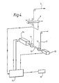
- Both cables 2 and 3 are attached to cable drums or pulleys 11 and 12 ( Figure 4) which wind in and out together to support the pilot In a suitable posture.
- a piston 9 and pulley arrangement acts as a damper to smooth the effects of sudden changes of tension In the cable 3.
- the piston 9 and pulley arrangement also enables the length of the head restraint cable 3 to be adjusted independently of cable 2 so that the pilot is still able to move his head independently of his torso despite being supported.
- the piston 9 also has a position sensor incorporated in it which monitors the extra amount of head support cable which has been unwound due to the movement of the pilot's head relative to his body and signals this information to control unit 15.
- Head support cable 3 is attached to the pilot's helmet 4 by means of a clasp 8 slidably mounted on bracket 5 which is pivotally mounted to the helmet 4 so that the pilot is able to rotate his head, move it from side to side and to raise and tilt it backwards and forwards.
- Figure 2 shows the horseshoe shaped bracket 5 mounted on a pivot 6 at each side of the helmet. The pivots may be specially placed on the helmet or else existing pivot points, such as those provided for the helmet visor 7, may be used. The pivoting action of the bracket 5 enables the pilot to tilt his head.
- the dotted outlines 5' and 5" show the possible successive positions of the bracket as the pilot tilts his head forward.
- the pivot points 6 may also be mounted on slotted brackets on the other side of the helmet, (not shown), that the bracket 5 can be moved up and down the helmet to compensate for changes in the centre of mass of a pilot's head. These changes may be due to physical differences between pilots or to equipment such as a night sights attached to the helmet.
- the clasp 8 has a series of roller bearings 9 mounted on it so that it can slide around bracket 5 and enable the pilot to rotate his head while the cable 3 is under tension.
- Figures 9 A - D show an alternative helmet bracket in more detail.
- An inner sliding rail 91 which would normally be held in a central position by two springs 92, but when pulled by the head support cable, can slide out from the main runners to enable the pilot's head to be supported when looking around at angles greater than 90°.
- the tension in cables 2 and 3 is monitored and controlled by the system shown in Figure 4.
- the restraining cables 2 and 3 are wound on to pulleys 12 and 11 respectively on a common shaft 10.
- Shaft 10 has an angular position sensing unit 13 for example an optical shaft encoder at one end and a drive motor 14 at the other end. Both the position sensing unit 13 and motor 14 are connected to a microprocessor control unit 15 which calculates the appropriate amount of tension required In cables 2 and 3.
- the control unit 15 also receives data representing g-forces from an accelerometer 16 and using that data and data from the position sensor 13 and it calculates the amount of supporting force required to counter the current g-force on the pilot's head and body.
- Control unit 15 sends appropriate torque control signals to the motor 14 which drives the shaft 10 and winds the support cables 2 and 3 onto pulleys 11 and 12 and pulls cables 2 and 3 to their correct tension.
- Accelerometer 16 is placed in the cockpit in a position close to the pilot so that during manoeuvres in which the aircraft is subject to g-forces which vary depending on the position on the aircraft at which they are measured, the g-force data it transmits to the control unit 15 more accurately represents the g-force actually acting on the pilot.
- the two pulleys 11 and 12 maybe of different diameters so that they can wind and unwind appropriately different lengths of cable as the pilot leans forward or backward.
- the larger diameter of pulley 11 enables the shaft 10 to release and wind in in torso cable 2 and a proportionally greater length of head restraint cable 3 at the same time whilst maintaining the tension in both as determined by the control unit 15.
- piston actuators 9 There are several types of piston actuators 9 on the market which could make the system feasible.
- the first type are servo-hydraulic actuators similar to the type used in 'fly-by-wire' systems, and provide a fast operating response and powerful piston force.
- the second type are electrically operated.
- Servo-hydraulic pistons suffer from one major disadvantage if they are to be mounted on the seat, and that is the problem of the disconnection of the hydraulic supply at the start of an emergency ejection.
- the pistons and their associated hydraulic controls may be mounted off the seat. Means (not shown) are provided to clamp the two cables 2 and 3 from a location on the seat, once they were in a retracted position as the seat left the aircraft. This could be achieved by Initially letting the cables run back through the seat at the start of the ejection sequence so that as the seat left the aircraft the pilot was pulled into an upright position (if required); the cables being detached from the aircraft and clamped on the ejection seat once this had been completed.
- the drums 11 and 12 are of similar diameter but are powered independently by independent stepper motors 14.
- the cables and the cable drums are mounted on the ejection seat and do not degrade the seats performance as they are made from lightweight materials.
- the drive system for the drums, ie, stepper motors 14 and gearing is mounted off the seat and is attached to solid structure such as the rear cockpit bulkhead.
- the accelerometer 16 detects the presence of high-g conditions and sends appropriate signals to the control unit 15.
- the control unit is arranged so that it only operates the system when a pre-set threshold of g-force has been exceeded.
- the threshold in this case is set at just over 1 g and when the accelerometer 16 detects a force greater than this threshold e.g. the force of 5g shown as acting in a direction vertically downwards on the pilot's head in Fig 1, the control unit 15 will signal motor 14 to apply a counteracting supporting tension to the support cables 2 and 3 i.e. in this example to produce a vertical component of force of 4g in a vertically upward direction so that the resultant force on the pilot's head remains at 1 g in the downward direction.
- the head support cable'3 is suspended from a point vertically above the pilot's head so that the cable 3 subtends the smallest possible angle from the vertical.
- the canopy would be stressed by the weight of pilot's head.
- the present arrangement compromises by attaching the head support system to a convenient point high on the ejector seat, taking into account the effects of pilot posture.
- Figure 6 shows the closed loop system necessary to control the tensions of cables 2 and 3. It is based on the servo mechanism principle, ie, 'a closed loop system in which the controlled loop is a mechanical position or rate' and assumes that the servo output is to an electric motor or step motor 14 used to power the cable drums 11 or 12.
- a suitable motor 14 for this arrangement could be powered from a 400 cycle AC supply or 28 volts DC supply, such as already exists In most modern military aircraft.
- the control loop comprises means 21 for providing tension feedback in which the tension in cables 2 or 3 are derived from strain guages (not shown) mounted on or woven into cables 2 or 3 adjacent to the torso harness and the 'horseshoe' helmet attachment points respectively.
- Tension feedback signals from the tension feedback means 21 are combined with signals from a controller 22 which sets the 'expected' tension in cables 2 and 3.
- the combined signals are processed in processor 23 to take of actual cable tension and produce control signals for stepper motor 14.
- a body position sensing circuit 24 calculates body position from the position of the appropriate cable drum 11 or 12 and combines this with accelerometer 16 signals to provide inputs to the controller 22.
- the system has certain properties:
- the motor 14 turns the cable drum 11/12 via a series of suitable cogs. This has the effect of increasing (or decreasing) the tension in the cables as required.
- the new tension level is then fed back into the system and a new signal sent to the motor as to whether it should continue to turn to increase the tension, stop if the tension in the cables is the tension required or unwind if the tension is too great.
- the weight of his torso will be supported by the standard harness shoulder straps if fitted. In this position support will be provided for the pilots head by the head support cable 3.
- the cable drums 11 and 12 each have a longitudinally extending arm 25 co-operating with arcuate slots 26 in the respective other drum and by means of which drums 11 and 12 are interlocked with limited but sufficient movement to permit independent head and torso movements (see Figure 5).
- the tension in the head support cable 3 in this way should any system failure occur then the relative movement of the two drums 11 and 12 and hence the two cables 2 and 3 will be limited and will therefore prevent any overstraining of the pilots neck.
- the cable drum 11 will also lock in position but will wind in as the pilot sits upright. With the 'go forward' lever in the unlocked position full support will be provided to both the head and torso by the control system. In the unlocked case the weight of the pilots body will be entirely supported by the torso support cable 2.
- Figure 7 shows a typical microprocessor control system suitable for controlling the operations of the head support systems of Figure 1.
- the microprocessor system is based around the M6800 Micro-computer family which uses a 16-bit address bus, and an 8-bit data bus. It is capable of operating at clock speeds up to 2 MHz and is powered by a 5 volt DC power supply.
- the central unit of the microprocessor system is the microprocessor unit (MPU) 70. This controls the operation of the system and generates all addresses placed on the address bus. When the MPU 70 generates an address, only the device with that address will communicate with the MPU.
- MPU microprocessor unit
- the 8-bit data bus 71 is common to all devices In the system and permits communication of data between the MPU and one of the following units addressed on the address bus:
- the microprocessor control unit shown in Figure 7 is configured to perform the operations of the system shown in Figure 6.
- the actual program which the MPU 70 follows in order to control the peripheral devices such as the step motors 14 is contained in the three read only memory units 72, 73 and 74. These units could be replaced by eraserable programmable read only memories which can be programmed and then realtered as the program is refined.
- the three random access units 75, 76 and 77 are used by the MPU during the execution of the main program for the temporary storage of data.
- the seven peripheral interface adaptors 78 to 85 act as interface units for information entering the system from accelerometers 16, optical shaft encoder sensors 13, cable drums 11 and 12 and strain guages 'not shown) mounted on each support cable 2/3. Information output from the system is to the two step motor driver chips 79, which will control the operation of the two step motors 14 one mounted on the gearing to each of the two cable drums 11 and 12.
- the optical shaft encoders 13 that interface with the peripheral interface adaptors 78 have two different sets of information associated with each one.
- One set is from a binary counter (not shown) which reads the shaft and counts the number of pulses outputed from the device, whilst the second set of information relates to the direction in which the shaft is turning. Both sets of information will be fed into the allocated side adaptor 78 at the same time, when adaptor 78 is commanded to 'read'. The information will then be interpreted by the program as two sets of data, from which it can calculate the amount of cable that has wound in, or unwound from each drum (11 or 12).
- the A - D converter used in this design requires an input of 0 to + 10V, or from 0 to +20V. Due to the small nature of the signals from the strain gauges, the first of these options would be the most suitable. To achieve this, the signal would need to be passed through an operational amplifier, and possibly a voltage level translator to ensure that maximum strain in the cables, allowing for a safety factor of about 1.5, produces an output of 0 - +10 volts. The operational amplifiers for each set of two sets of three strain gauges would need different gain characteristics to produce the required output due to the differing levels of maximum tension likely to be experienced in each of the cables. Each individual strain gauge would need to have its output passed through a separate A - D converter before being passed to the peripheral Interface adaptor Input lines 80, 81, 82, and may also initially require some form of noise filtering before being passed to the A - D converter.
- each accelerometer 16 will require its own noise filter, and A - D converter before being passed to the peripheral Interface Adaptor 83, 84, 85 input lines.
- step motor driver device requires only three inputs, (input, direction and reset), and because of this, both step motor driver chips can be connected to the same side of one adaptor 79.
- Figure 8 shows how the ideal support will be offered to the pilot by directing the forces from the head and torso support wires 2 and 3 in a perpendicular direction back along an axis parallel to that of the aircraft longitudinal axis, and not just back to the centre of the seat, thus ensuring that the support enables the pilot to raise his head without the cable 3 also trying to pull his head back to the centre of the seat head box 86.
- two constant radius arcs of support 87 and 89 can be defined, one for the head support wire 3 and one for the torso support wire 2.
- These arcs are defined by the arcs of travel of the connection points of the wires to the pilot's helmet and torso, as he moves his position to look round the side of the seat from his normal sitting posture.
- the support arrangement should allow the pilot to move within these arcs of travel and still be supported during high g manoeuvres. To achieve this, and at the same time still directing the forces back from the pilot's head in a perpendicular arrangement, it will be necessary to provide a supporting structure that moves in the same arc of travel as the pilot's head (and torso).
- this entails a structure that protrudes from the side of the ejection seat head box to take a position directly behind the pilot's head.
- Such an arrangement would clearly not want to be permanently projecting from the side of the head box for fear of obscuring the pilot's view during other manoeuvres, and this arrangement could therefore be met by an arm structure 88 that moves out on the required arc of travel 87 when required, but otherwise remained in a retracted position.
- the support system may also be adapted to act as a restraint system during emergency ejection.
- the separation of the cables 2 and 3 from the pilot either when leaving the aircraft or upon ejection enables the cables to detach cleanly and without snagging any part of the pilot or ejection seat.
- Those skilled in the art will be able to suggest quick release mechanisms to enable the cables 2 and 3 to disconnect quickly.
- the head restraint system shown in the example given above comprises a single support cable acting on a point behind the pilot's head and a single cable attached to his torso
- two parallel cables may be attached to the pilot's torso to improve the pilot's comfort and to also enable the angle of twist of the pilot's torso to be calculated and used to further refine the tensions applied.
- the system could be adapted to support the pilot against forces acting in directions other than vertical downward g forces.
- a safety system could be incorporated in the support system so that in the event of an emergency the supporting cables would be automatically severed from the pilot's body and head to avoid the danger of entanglement during ejection.
Landscapes
- Business, Economics & Management (AREA)
- Emergency Management (AREA)
- Engineering & Computer Science (AREA)
- Aviation & Aerospace Engineering (AREA)
- Helmets And Other Head Coverings (AREA)
- Seats For Vehicles (AREA)
- Force Measurement Appropriate To Specific Purposes (AREA)
Priority Applications (1)
| Application Number | Priority Date | Filing Date | Title |
|---|---|---|---|
| AT87906091T ATE51198T1 (de) | 1986-09-19 | 1987-09-18 | Rueckhaltesystem fuer flugzeugbesatzung. |
Applications Claiming Priority (2)
| Application Number | Priority Date | Filing Date | Title |
|---|---|---|---|
| GB868622560A GB8622560D0 (en) | 1986-09-19 | 1986-09-19 | Support system |
| GB8622560 | 1986-09-19 |
Publications (2)
| Publication Number | Publication Date |
|---|---|
| EP0282543A1 EP0282543A1 (en) | 1988-09-21 |
| EP0282543B1 true EP0282543B1 (en) | 1990-03-21 |
Family
ID=10604436
Family Applications (1)
| Application Number | Title | Priority Date | Filing Date |
|---|---|---|---|
| EP87906091A Expired EP0282543B1 (en) | 1986-09-19 | 1987-09-18 | Aircrew restraint systems |
Country Status (6)
| Country | Link |
|---|---|
| US (1) | US4967985A (pt) |
| EP (1) | EP0282543B1 (pt) |
| JP (1) | JPH0698958B2 (pt) |
| BR (1) | BR8707464A (pt) |
| GB (1) | GB8622560D0 (pt) |
| WO (1) | WO1988001968A1 (pt) |
Families Citing this family (41)
| Publication number | Priority date | Publication date | Assignee | Title |
|---|---|---|---|---|
| US4784352A (en) * | 1986-05-20 | 1988-11-15 | Rockwell International Corporation | Forward posture support seat system |
| US4923147A (en) * | 1988-09-27 | 1990-05-08 | Rockwell International Corporation | Head support/spine offloading ejection seat insert |
| US4909459A (en) * | 1988-11-03 | 1990-03-20 | The United States Of America As Represented By The Secretary Of The Navy | Helmet-mounted head restraint |
| GB8910082D0 (en) * | 1989-05-03 | 1989-09-20 | Smiths Industries Plc | Pilot's g helmet |
| GB9015177D0 (en) * | 1990-07-10 | 1990-08-29 | Secr Defence | A helmet loader for flight simulation |
| FR2672565B1 (fr) * | 1991-02-12 | 1993-06-04 | Intertechnique Sa | Equipement de tete a bras articule. |
| FR2672702B1 (fr) * | 1991-02-12 | 1994-07-01 | Intertechnique Sa | Viseur de casque. |
| US5376128A (en) * | 1992-08-31 | 1994-12-27 | The United States Of America As Represented By The Administrator Of The National Aeronautics And Space Administration | Control system for prosthetic devices |
| US5267708A (en) * | 1992-09-28 | 1993-12-07 | Rockwell International Corp. | Head support apparatus |
| GB2289615A (en) * | 1994-05-20 | 1995-11-29 | Robert Francis John | Combined head and neck protection system |
| US6299102B2 (en) * | 1995-05-12 | 2001-10-09 | H. Koch & Sons, Inc. | Aviation crash sensor |
| US6428043B1 (en) * | 2001-02-22 | 2002-08-06 | Arnold Gray Wooten | Vehicle head restraint device |
| US6381758B1 (en) * | 2001-02-22 | 2002-05-07 | Vanderbilt University | Head restraint system for racecar drivers |
| US8375472B2 (en) | 2001-04-19 | 2013-02-19 | Simpson Performance Products, Inc. | Multi-point tethering system for head and neck restraint devices |
| US8272074B1 (en) * | 2003-12-03 | 2012-09-25 | Simpson Performance Products, Inc. | Head restraint device having a support member with back and shoulder portions |
| US6810535B1 (en) * | 2002-06-19 | 2004-11-02 | Speed Solutions, Inc. | Helmet restraint system |
| US6751809B1 (en) * | 2003-02-19 | 2004-06-22 | Key Safety Systems, Inc. | Helmet restraint system |
| US20050065757A1 (en) * | 2003-09-19 | 2005-03-24 | White Samer R. | System and method for estimating displacement of a seat-belted occupant |
| US7404402B2 (en) * | 2006-03-13 | 2008-07-29 | M & B Innovations Limited | Whiplash restrainer |
| CA2900177C (en) | 2015-08-11 | 2024-02-13 | J.J. Mackay Canada Limited | Single space parking meter retrofit |
| US7926787B2 (en) * | 2006-11-21 | 2011-04-19 | Blue Sky Decks, Llc | Elevated platform and method of elevating the same |
| US8702059B2 (en) * | 2006-11-21 | 2014-04-22 | Craig Wieland | Elevated platform and method of elevating the same |
| US10537147B1 (en) * | 2008-04-14 | 2020-01-21 | Simpson Performance Products, Inc. | Multi-point tethering system for head and neck restraint devices |
| CA2664291C (en) | 2008-04-25 | 2013-09-17 | J.J. Mackay Canada Limited | Improved data collection system for electronic parking meters |
| US20090309346A1 (en) * | 2008-06-13 | 2009-12-17 | Millenworks | Intelligent Vehicle Safety Restraint System |
| US8414026B1 (en) | 2010-03-17 | 2013-04-09 | Armorworks Enterprises LLC | Mobile crew restraint and seating system |
| GR20100100591A (el) * | 2010-10-13 | 2012-05-18 | Παυλος Δημητριου Γιαννακοπουλος | Προεντατηρες με καλωδια bowden και εκτινασσομενο καθισμα εφοδιασμενο με αυτους |
| US8746739B2 (en) * | 2011-06-22 | 2014-06-10 | Carlston Life Support Systems, Inc. | Aircrew restraint system with integrated communications and controls |
| CN102407943B (zh) * | 2011-10-11 | 2014-04-16 | 中国人民解放军第三军医大学野战外科研究所 | 头颈部损伤防护装置 |
| CA145137S (en) | 2012-04-02 | 2013-07-22 | Jj Mackay Canada Ltd | Single space parking meter |
| US10039337B2 (en) | 2012-11-27 | 2018-08-07 | Necksgen, Inc. | Head and neck restraining system |
| US11013285B1 (en) | 2012-11-27 | 2021-05-25 | NecksGen Inc. | Head and neck restraining system with an adjustable tether |
| US10786030B1 (en) * | 2012-11-27 | 2020-09-29 | Necksgen, Inc. | Head and neck restraining system |
| CA2960415C (en) * | 2014-09-10 | 2023-03-21 | Thumbprint Solutions Inc. | System for mitigating musculoskeletal stresses from head-related moments exerted on a person |
| USRE48566E1 (en) | 2015-07-15 | 2021-05-25 | J.J. Mackay Canada Limited | Parking meter |
| USD813059S1 (en) | 2016-02-24 | 2018-03-20 | J.J. Mackay Canada Limited | Parking meter |
| ES2703806A1 (es) * | 2017-09-11 | 2019-03-12 | Cortes Alberto Martinez | Sistema protector cervical |
| CA3031936A1 (en) | 2019-01-30 | 2020-07-30 | J.J. Mackay Canada Limited | Spi keyboard module for a parking meter and a parking meter having an spi keyboard module |
| US11922756B2 (en) | 2019-01-30 | 2024-03-05 | J.J. Mackay Canada Limited | Parking meter having touchscreen display |
| EP4252571B1 (en) | 2022-03-30 | 2025-06-18 | Airbus Defence and Space GmbH | Active neck protection system |
| DE102023102424B3 (de) * | 2023-02-01 | 2024-03-14 | Deutsches Zentrum für Luft- und Raumfahrt e.V. | Exoskelettarm-Hilfe im Luftfahrzeugcockpit für hohe Beschleunigungen |
Family Cites Families (9)
| Publication number | Priority date | Publication date | Assignee | Title |
|---|---|---|---|---|
| US2195334A (en) * | 1938-06-21 | 1940-03-26 | Mills Equipment Co Ltd | Safety apparatus for retaining persons in the seats of aircraft or other vehicles |
| GB656079A (en) * | 1948-12-31 | 1951-08-08 | Reid & Sigrist Ltd | Improvements in or relating to head and like supports for persons subjected to acceleration forces |
| US3074669A (en) * | 1959-08-28 | 1963-01-22 | Svenska Aeroplan Ab | Device to protect an occupant against bodily injury during emergency escape from aircraft |
| US3099261A (en) * | 1960-09-06 | 1963-07-30 | Boeing Co | Full body restraint system |
| US3178136A (en) * | 1963-02-01 | 1965-04-13 | Rocket Power Inc | Safety device for a seat occupant embodying a ballistic actuated reel |
| DE2249759C2 (de) * | 1972-10-11 | 1982-11-18 | Daimler-Benz Ag, 7000 Stuttgart | Haltesystem für die Insassen eines Kraftfahrzeuges |
| US4477041A (en) * | 1982-08-19 | 1984-10-16 | Michael Dunne | Head and neck restraint system |
| US4664341A (en) | 1984-09-04 | 1987-05-12 | Rockwell International Corporation | Head restraint system |
| US4667904A (en) * | 1984-09-28 | 1987-05-26 | The Boeing Company | Torso restraint with in flight and ejection activation modes |
-
1986
- 1986-09-19 GB GB868622560A patent/GB8622560D0/en active Pending
-
1987
- 1987-09-18 BR BR8707464A patent/BR8707464A/pt not_active IP Right Cessation
- 1987-09-18 US US07/199,300 patent/US4967985A/en not_active Expired - Fee Related
- 1987-09-18 WO PCT/GB1987/000654 patent/WO1988001968A1/en not_active Ceased
- 1987-09-18 JP JP62505539A patent/JPH0698958B2/ja not_active Expired - Lifetime
- 1987-09-18 EP EP87906091A patent/EP0282543B1/en not_active Expired
Also Published As
| Publication number | Publication date |
|---|---|
| GB8622560D0 (en) | 1987-02-04 |
| US4967985A (en) | 1990-11-06 |
| BR8707464A (pt) | 1988-12-06 |
| JPH01500989A (ja) | 1989-04-06 |
| EP0282543A1 (en) | 1988-09-21 |
| WO1988001968A1 (en) | 1988-03-24 |
| JPH0698958B2 (ja) | 1994-12-07 |
Similar Documents
| Publication | Publication Date | Title |
|---|---|---|
| EP0282543B1 (en) | Aircrew restraint systems | |
| US4784352A (en) | Forward posture support seat system | |
| JP2577260B2 (ja) | 座席挿入物 | |
| US7155747B2 (en) | Head stabilizing system | |
| US6810535B1 (en) | Helmet restraint system | |
| US5252070A (en) | Helmet loader for flight simulation | |
| US5046687A (en) | Adaptive torso restraint system | |
| EP0590497A1 (en) | Head support apparatus | |
| US8590843B2 (en) | Cyclic stick for mechanically transmitting commands for controlling a rotorcraft, the stick having a lever arm that is amplified selectively in the event of an emergency | |
| US20040255368A1 (en) | Head stabilizing system | |
| US4301983A (en) | High acceleration protective seat | |
| US5272422A (en) | Head equipment with articulated arm | |
| CN108423175A (zh) | 一种绳悬挂刀具的树障清理空中机器人 | |
| CN108377781A (zh) | 一种悬挂刀具结构的树障清理空中机器人 | |
| CN208439427U (zh) | 一种绳悬挂刀具的树障清理空中机器人 | |
| EP4097005B1 (de) | Elektrische aufstiegshilfe | |
| JP2001225797A (ja) | 耐重力加速度服内圧力の制御方法、制御装置及び制御システム | |
| US4607811A (en) | Propulsion unit for hang glider type aircraft, and aircraft fitted with the propulsion unit | |
| EP4252571B1 (en) | Active neck protection system | |
| US5033697A (en) | Pilot head support apparatus | |
| CN223778572U (zh) | 一种飞行器防坠辅助保护装置 | |
| CN208446135U (zh) | 一种悬挂刀具结构的树障清理空中机器人结构 | |
| JPH01262296A (ja) | 前方姿勢支持座席システム | |
| Deakin | Military aircrew head support system | |
| DVL-I-This | Positioning of Aircrews--Ultima Ratio of G Protection? |
Legal Events
| Date | Code | Title | Description |
|---|---|---|---|
| PUAI | Public reference made under article 153(3) epc to a published international application that has entered the european phase |
Free format text: ORIGINAL CODE: 0009012 |
|
| 17P | Request for examination filed |
Effective date: 19880621 |
|
| AK | Designated contracting states |
Kind code of ref document: A1 Designated state(s): AT BE CH DE FR GB IT LI LU NL SE |
|
| 17Q | First examination report despatched |
Effective date: 19890706 |
|
| GRAA | (expected) grant |
Free format text: ORIGINAL CODE: 0009210 |
|
| ITF | It: translation for a ep patent filed | ||
| AK | Designated contracting states |
Kind code of ref document: B1 Designated state(s): AT BE CH DE FR GB IT LI LU NL SE |
|
| PG25 | Lapsed in a contracting state [announced via postgrant information from national office to epo] |
Ref country code: AT Effective date: 19900321 |
|
| REF | Corresponds to: |
Ref document number: 51198 Country of ref document: AT Date of ref document: 19900415 Kind code of ref document: T |
|
| REF | Corresponds to: |
Ref document number: 3761967 Country of ref document: DE Date of ref document: 19900426 |
|
| ET | Fr: translation filed | ||
| PG25 | Lapsed in a contracting state [announced via postgrant information from national office to epo] |
Ref country code: LU Free format text: LAPSE BECAUSE OF NON-PAYMENT OF DUE FEES Effective date: 19900930 |
|
| PLBE | No opposition filed within time limit |
Free format text: ORIGINAL CODE: 0009261 |
|
| STAA | Information on the status of an ep patent application or granted ep patent |
Free format text: STATUS: NO OPPOSITION FILED WITHIN TIME LIMIT |
|
| 26N | No opposition filed | ||
| ITTA | It: last paid annual fee | ||
| PGFP | Annual fee paid to national office [announced via postgrant information from national office to epo] |
Ref country code: NL Payment date: 19920930 Year of fee payment: 6 |
|
| PGFP | Annual fee paid to national office [announced via postgrant information from national office to epo] |
Ref country code: BE Payment date: 19921013 Year of fee payment: 6 |
|
| PG25 | Lapsed in a contracting state [announced via postgrant information from national office to epo] |
Ref country code: BE Effective date: 19930930 |
|
| BERE | Be: lapsed |
Owner name: BRITISH AEROSPACE P.L.C. Effective date: 19930930 |
|
| PG25 | Lapsed in a contracting state [announced via postgrant information from national office to epo] |
Ref country code: NL Effective date: 19940401 |
|
| NLV4 | Nl: lapsed or anulled due to non-payment of the annual fee | ||
| EAL | Se: european patent in force in sweden |
Ref document number: 87906091.1 |
|
| PGFP | Annual fee paid to national office [announced via postgrant information from national office to epo] |
Ref country code: FR Payment date: 19990807 Year of fee payment: 13 |
|
| PGFP | Annual fee paid to national office [announced via postgrant information from national office to epo] |
Ref country code: CH Payment date: 19990813 Year of fee payment: 13 |
|
| PGFP | Annual fee paid to national office [announced via postgrant information from national office to epo] |
Ref country code: SE Payment date: 19990816 Year of fee payment: 13 |
|
| PGFP | Annual fee paid to national office [announced via postgrant information from national office to epo] |
Ref country code: GB Payment date: 19990818 Year of fee payment: 13 |
|
| PGFP | Annual fee paid to national office [announced via postgrant information from national office to epo] |
Ref country code: DE Payment date: 19990825 Year of fee payment: 13 |
|
| PG25 | Lapsed in a contracting state [announced via postgrant information from national office to epo] |
Ref country code: GB Free format text: LAPSE BECAUSE OF NON-PAYMENT OF DUE FEES Effective date: 20000918 |
|
| PG25 | Lapsed in a contracting state [announced via postgrant information from national office to epo] |
Ref country code: SE Free format text: THE PATENT HAS BEEN ANNULLED BY A DECISION OF A NATIONAL AUTHORITY Effective date: 20000929 |
|
| PG25 | Lapsed in a contracting state [announced via postgrant information from national office to epo] |
Ref country code: LI Free format text: LAPSE BECAUSE OF NON-PAYMENT OF DUE FEES Effective date: 20000930 Ref country code: CH Free format text: LAPSE BECAUSE OF NON-PAYMENT OF DUE FEES Effective date: 20000930 |
|
| GBPC | Gb: european patent ceased through non-payment of renewal fee |
Effective date: 20000918 |
|
| REG | Reference to a national code |
Ref country code: CH Ref legal event code: PL |
|
| EUG | Se: european patent has lapsed |
Ref document number: 87906091.1 |
|
| PG25 | Lapsed in a contracting state [announced via postgrant information from national office to epo] |
Ref country code: FR Free format text: LAPSE BECAUSE OF NON-PAYMENT OF DUE FEES Effective date: 20010531 |
|
| PG25 | Lapsed in a contracting state [announced via postgrant information from national office to epo] |
Ref country code: DE Free format text: LAPSE BECAUSE OF NON-PAYMENT OF DUE FEES Effective date: 20010601 |
|
| REG | Reference to a national code |
Ref country code: FR Ref legal event code: ST |
|
| PG25 | Lapsed in a contracting state [announced via postgrant information from national office to epo] |
Ref country code: IT Free format text: LAPSE BECAUSE OF NON-PAYMENT OF DUE FEES;WARNING: LAPSES OF ITALIAN PATENTS WITH EFFECTIVE DATE BEFORE 2007 MAY HAVE OCCURRED AT ANY TIME BEFORE 2007. THE CORRECT EFFECTIVE DATE MAY BE DIFFERENT FROM THE ONE RECORDED. Effective date: 20050918 |