EP0282593A1 - Appareil formant un faisceau laser - Google Patents
Appareil formant un faisceau laser Download PDFInfo
- Publication number
- EP0282593A1 EP0282593A1 EP87904116A EP87904116A EP0282593A1 EP 0282593 A1 EP0282593 A1 EP 0282593A1 EP 87904116 A EP87904116 A EP 87904116A EP 87904116 A EP87904116 A EP 87904116A EP 0282593 A1 EP0282593 A1 EP 0282593A1
- Authority
- EP
- European Patent Office
- Prior art keywords
- laser beam
- sleeve member
- forming apparatus
- beam forming
- inside surface
- Prior art date
- Legal status (The legal status is an assumption and is not a legal conclusion. Google has not performed a legal analysis and makes no representation as to the accuracy of the status listed.)
- Granted
Links
Images



Classifications
-
- G—PHYSICS
- G03—PHOTOGRAPHY; CINEMATOGRAPHY; ANALOGOUS TECHNIQUES USING WAVES OTHER THAN OPTICAL WAVES; ELECTROGRAPHY; HOLOGRAPHY
- G03F—PHOTOMECHANICAL PRODUCTION OF TEXTURED OR PATTERNED SURFACES, e.g. FOR PRINTING, FOR PROCESSING OF SEMICONDUCTOR DEVICES; MATERIALS THEREFOR; ORIGINALS THEREFOR; APPARATUS SPECIALLY ADAPTED THEREFOR
- G03F7/00—Photomechanical, e.g. photolithographic, production of textured or patterned surfaces, e.g. printing surfaces; Materials therefor, e.g. comprising photoresists; Apparatus specially adapted therefor
- G03F7/70—Microphotolithographic exposure; Apparatus therefor
- G03F7/70058—Mask illumination systems
- G03F7/70075—Homogenization of illumination intensity in the mask plane by using an integrator, e.g. fly's eye lens, facet mirror or glass rod, by using a diffusing optical element or by beam deflection
-
- B—PERFORMING OPERATIONS; TRANSPORTING
- B23—MACHINE TOOLS; METAL-WORKING NOT OTHERWISE PROVIDED FOR
- B23K—SOLDERING OR UNSOLDERING; WELDING; CLADDING OR PLATING BY SOLDERING OR WELDING; CUTTING BY APPLYING HEAT LOCALLY, e.g. FLAME CUTTING; WORKING BY LASER BEAM
- B23K26/00—Working by laser beam, e.g. welding, cutting or boring
- B23K26/02—Positioning or observing the workpiece, e.g. with respect to the point of impact; Aligning, aiming or focusing the laser beam
- B23K26/06—Shaping the laser beam, e.g. by masks or multi-focusing
- B23K26/073—Shaping the laser spot
- B23K26/0732—Shaping the laser spot into a rectangular shape
-
- G—PHYSICS
- G02—OPTICS
- G02B—OPTICAL ELEMENTS, SYSTEMS OR APPARATUS
- G02B27/00—Optical systems or apparatus not provided for by any of the groups G02B1/00 - G02B26/00, G02B30/00
- G02B27/09—Beam shaping, e.g. changing the cross-sectional area, not otherwise provided for
-
- G—PHYSICS
- G02—OPTICS
- G02B—OPTICAL ELEMENTS, SYSTEMS OR APPARATUS
- G02B27/00—Optical systems or apparatus not provided for by any of the groups G02B1/00 - G02B26/00, G02B30/00
- G02B27/09—Beam shaping, e.g. changing the cross-sectional area, not otherwise provided for
- G02B27/0927—Systems for changing the beam intensity distribution, e.g. Gaussian to top-hat
-
- G—PHYSICS
- G02—OPTICS
- G02B—OPTICAL ELEMENTS, SYSTEMS OR APPARATUS
- G02B27/00—Optical systems or apparatus not provided for by any of the groups G02B1/00 - G02B26/00, G02B30/00
- G02B27/09—Beam shaping, e.g. changing the cross-sectional area, not otherwise provided for
- G02B27/0938—Using specific optical elements
- G02B27/0994—Fibers, light pipes
Definitions
- This invention relates to a laser beam forming apparatus for forming laser beams used for laser machining such as laser cuttin g ,laser welding and laser hardening, and more particularly to a laser beam forming apparatus for forming laser beams having a stable and uniform energy distribution.
- Japanese Patent Publication NO. SHO57-47249 there is disclosed a laser beam forming apparatus wherein an internal reflecting mirror having a mirror-finished cylindrical circumferential surface is mounted in a light beam optical system such as, for example, a laser beam optical system so that laser beams may be focussed through the reflecting mirror with a uniform energy density (or energy distribution).
- a light beam optical system such as, for example, a laser beam optical system so that laser beams may be focussed through the reflecting mirror with a uniform energy density (or energy distribution).
- a uniform energy density or energy distribution
- the energy distribution of the laser beams to be irradiated on an object to be processed thereby is in a similar relationship with that of the laser beams incident on a beam focussing lens before focussing, and therefore if the energy distribution of the laser beams before focussing is not uniform, then the laser beams to be 'irradiated onto the object to be worked thereby will become uneven.
- laser hardening if laser beams having an uneven energy distribution are used for irradiation, then such disadvantages as uneven hardening pattern and partial melting of the surface of the object to be hardened will occur.
- segment mirror system a mirror irradiation system wherein laser beams are reflected through a plurality of mirrors divided into a grid shape and then the reflected laser beams are focussed at the same one point to thereby make uniform the energy distribution of laser beams for irradiation, so-called segment mirror system.
- This segment mirror system has the following disadvantage. Stating in brief, this system requires high precision in working or machining and mounting of the mirrors, and as a result, the manufacturing cost of the mirrors becomes expensive, and also because the shape of the laser beams is fixed, there is need for replacement of mirrors for each of the objects to be irradiated therewith.
- a laser beam forming apparatus comprising a plurality of reflecting mirrors with the above-mentioned segment-mirrors interposed to achieve more uniform energy distribution of laser beams to be irradiated.
- this improved apparatus has unsolved points at issue in that (a) it lacks in stability for mode formation since it has a motor driving unit; (b) it is difficult to set the size of beams; whether the energy distribution of the laser beams to be formed by the apparatus is satisfactory or not depends on whether the energy distribution of the laser beams before focussing is satisfactory or not etc.
- the present invention has been made to solve the disadvantages and points at issue associated with the above-mentioned conventional laser beam forming apparatuses, and has for its object to provide a laser beam forming apparatus which does not require high precision working to form the mirror surface in the reflecting mirror and which can form readily laser beams having a macroscopically uniform energy distri- hution, even if the focussed incident beams are not " uniform.
- Another object of the present invention is to provide a laser beam forming apparatus wherein laser beams are allowed to make incidence from one end of a sleeve member whose inside surface is mirror-finished so as to achieve an extremely enhanced reflectivity, so that the laser beams may be subjected to multi-reflection therein, and then the multi- reflected laser beams are synthesized on the other end of the sleeve member.
- a further object of the present invention is to provide a laser beam forming apparatus wherein the laser beams to be focussed are allowed to make incidence from one side of a scope which comprises a conical mirror whose outer surface is mirror-finished is concentrically mounted inside a sleeve member whose inside surface is mirror-finished so that laser beams of a ring mode can be produced on the other side of the scope.
- a laser beam forming apparatus characterized in that, inside a laser beam optical system including at least one beam focussing lens and one image forming lens, a sleeve member having a reflective inside surface is interposed between said beam focussing lens and said image forming lens, said sleeve member being arranged to enable the laser beams passing through the optical system to be subjected to multi-reflection therein so as to be changed into beams of a predetermined shape having a microscopically uniform energy distribution.
- a laser beam forming apparatus as set forth in said first aspect, characterized in that said sleeve member having reflective inside surface has inclined inside surfaces so that an outlet for laser beams having a 'sectional area which is different from that of an inlet for laser beams can be formed.
- a laser beam forming apparatus as set forth in said first aspect, characterized in that said sleeve member having a reflective inside surface is a bent laser beam reflecting pipe.
- a laser beam forming apparatus as set forth in said first aspect, characterized in that said sleeve member having a reflective inside surface is cylindrical, and a conical mirror whose outside surface is mirror-.finished is concentrically mounted in the sleeve member so as to produce laser beams of a ring mode.
- the first embodiment is shown in Figure 1.
- the light beam optical system for example, the laser beam optical system shown is arranged to convert unevenly distributed beams D1 of any given shape into uniformly distributed beams D 1 over a single zone or plural zones.
- reference numeral 1 denotes a beam focussing lens, 2 an image forming lens, and 3 a sleeve member having a reflective inside surface interposed between both the lenses 1 and 2.
- the sleeve member 3 having a reflective inside surface should preferably be of water-cooled type.
- the above-mentioned beam focussing lens 1 serves to introduce the laser beams into the inlet of the above-mentioned sleeve member 3 having a reflective inside surface.
- the above-mentioned image forming lens 2 serves to enlarge or reduce the laser beams which emerged from the outlet,of the sleeve member 3 having a reflective inside surface, into a predetermined size.
- the optical system may be constituted by mirrors (reflective mirrors) instead of these lenses 1 and 2.
- the beam focussing lens 1 may be omitted.
- Reference character W denotes a work to be irradiated by predetermined uniformly distributed beams D 2 .
- the above-mentioned sleeve member 3 having a reflective inside surface is arranged to form a beam reflecting zone of a square sectional shape.
- the sleeve member 3 is constituted by a pair of left and right side plates 4 and 5, an upper plate 6 and a lower plate 7 which are mounted between both side plates 4 and 5 so that their positions can be varied freely.
- the inside surfaces of the plates 4, 5, 6 and 7 are mirror-finished to allow the laser beams introduced therein to be subjected to multiple-reflection.
- the upper and lower plates 6 and 7 may be inclined, as occasion demands, by an angle ( ⁇ ) so that the size (sectional area d' 1 x d' 2 ) of the outlet is smaller than the size (sectional area d 1 x d 2 ) of the inlet or vice versa.
- ⁇ angle
- both the side plates 4 and 5 are located in parallel relationship ,with each other, and the upper and lower plates 6 and 7 are inclined, respectively, by an angle (8) so that they approach towards each other from the inlet for laser beams to the outlet thereof. That is to say, the sleeve member 3 having a reflective inside surface of a wedge shape is shown.
- the beams are subjected to multiple-reflection within the beam reflection zone in the sleeve member 3 so as to be converted into beams of a predetermined shape having a macroscopically uniform intensity distribution when emerging from the outlet.
- the laser beams will form a uniform, rectangular image on the surface of the sample or work through the action of the image forming lens 2.
- the reason for the use of the above-mentioned expression "macroscopically uniform intensity distribution" is that, since the laser beams obtained by the optical system of the kind specified above include interference fringes, they are not uniformly distributed locally.
- the shape of the laser beams may be varied continuously. Further, by varying the distance between the outlet of the sleeve member 3 having a reflective inside surface and the image forming lens 2 and that between the image forming lens 2 and the surface of the sample or work, the size of the laser beams can be varied continuously.
- the macroscopic laser beam distribution obtained by the internal reflection can be made uniform by deciding the length (L) of the sleeve member within the range given by the following formula.
- the number N of the main interference fringes attributable to the formation of laser beams at that time is given by the following formula.
- ⁇ denotes the wave length of the incident laser beams. Therefore, in case it is desired to form laser beams of a square shape to be irradiated, a predetermined number of interference fringes is given by the following formula.
- the number N of the interference fringes is inversely proportional to the length L of the sleeve member 3.
- the length L of the sleeve member 3 required to ensure a macroscopic uniformity is determined by. the long side and given by the following formula.
- the number of the interference fringes on the long side is given by the following formula.
- the number of the interference fringes on the short side is given by the following formula.
- “d l” denotes the length of the long side
- “d 2” the length of the short side
- " ⁇ ” the wavelength of the incident beams
- "f” the focal length of the beam focussing lens
- "D” the diameter of the incident, beams
- N 1 the number of the interference fringes measured along the long side
- “N 2” the number of the interference fringes measured along the short side. Therefore, in case of rectangular beams having a large aspect ratio (d 1 /d 2 ), even if the number N l of the interference fringes on the long side is proper, the number N 2 of the interference fringes on the short side becomes- smaller at the inverse square of the aspect ratio.
- the number of reflections of the beams can be increased sharply by inclining the upper and lower plates 6 and 7 of the sleeve member 3 having a reflective inside surface by an angle (6), defining the section of the outlet to obtain a beam shape of the size required (d' 1 x d' 2 ) and defining the section of the inlet to have a size required to secure a sufficient number of interference fringes, as shown in Figures 1, 2 and 3. Therefore, it becomes possible to change the beam shape (aspect ratio) having a macroscopically uniform intensity distribution into any desired value and change the number of interference fringes independently.
- the number of reflections made by the side plates 4, 5 can be made equal to that of reflections made by upper and lower plates 6, 7. Further, by using the sleeve member 3 having inclined reflective inside surfaces, even in case of forming square beams, it becomes possible to increase the number of reflections beyond the value obtained by the above-mentioned formula (1) with a limited length L of the sleeve member 3.
- the number of reflections obtained thereby will increase beyond that obtained in the case where the upper and lower plates 6 and 7 are located in parallel relationship with each other.
- the beam absorption losses on the surface of the mirror may become high.
- a combination of a cylindrical lens (or cylindrical mirror) and a convex lens may be used instead of the above-mentioned beam focussing lens 1 or alternatively, the astigmatism of a spherical mirror may be utilized. By go doing, it becomes possible to increase or decrease the number of reflections.
- the sleeve member 3 having a reflective inside surface and whose outlet is smaller than the inlet is shown in Figure 1, it becomes possible to reduce the number of reflections, as occasion demands, by locating the upper and lower plates 6 and 7 so as to incline by a predetermined angle to diverge towards the outlet or reduce the number of interference fringes along one side thereof.
- a sleeve member 30 having reflective inside surfaces in this embodiment comprises four pieces of plates, i.e., an upper plate 6, intermediate stage plates 7, 8 and a lower plate 9 mounted between a pair of left and right side plates 4 and 5 so that the plates 6, 7, 8 and 9 may be changed freely in position.
- the previously mentioned embodiment has a single beam reflecting zone, whilst this embodiment has a plurality of beam reflecting zones. Accordingly, both the upper and lower surfaces of each of the intermediate stage plates 8, 9 are mirror-finished.
- the sleeve member 30 having reflective inside surfaces of such a construction it is possible to produce laser beams which are uniform over the plurality of beam reflecting zones and whose intensities are different between the zones. Accordingly, it is possible to satisfactorily harden curved surfaces of gears, for example.
- the third embodiment of the present invention is shown in Figure 7. As shown in this drawing, it is not always necessary to locate the beam reflecting zones adjacent to one another at the outlet of a sleeve member 31 having reflective inside surfaces, and instead five pieces of plates, i.e., 'an upper plate 6, a lower plate 7 and plates 8 1 , 8 2 and 9' may be spaced apart and formed with different shapes.
- the aforementioned second embodiment is suited to regulate the proportion of the area occupied by the beams at the inlet of the sleeve member 31 having reflective inside surfaces (the proportion of the dome power to be distributed to each of the beam reflecting zones), whilst this third embodiment is suited to the case where a plurality of reflecting mirrors 12 are used.
- the arrangement wherein the plate members 6 to 9' of the sleeve member 31 having reflective inside surfaces can be moved only in the vertical direction (or primary dimensional direction) was described as an example, but it is obvious that the plate members may be moved transversely (or secondary dimensional direction).
- the section of the beam reflecting zone of the sleeve member 3 having a reflective inside surface is not to be limited to square, but it may be round, for example, and alternatively if neglecting the uniformity to some degree, it is possible to form the section of the beam reflecting zone in a polygonal or elliptical shape or a composite shape of them.
- a beam focussing lens. 1 is mounted inside a sleeve member 13 to focus- laser beams 11 on the side of the inlet, and on the side of the outlet a laser beam reflecting pipe 32 which serves as the sleeve member having a reflective inside surface is located opposite to an image forming lens 2 on the side of the outlet.
- the inside surface of the laser beam reflecting pipe 32 is mirror-finished to provide an extremely excellent reflectivity and is bent in generally L shape or at right angles, whilst the image forming lens 2 is located opposite to the side surface S of a work W 1 .
- the incident laser beams 11 having. uneven distribution D1 are focussed by the focussing lens 1 located on the surface of the inlet, and then projected onto the inside surface of the laser beam reflecting pipe 32 so that they may be subjected to the multi-reflection by the inside surface thereof, and subsequently synthesized at the outlet of the pipe 32 to produce beams having a uniform and completely rectangular energy distribution. Therefore, the energy distribution of the laser beams to be irradiated through the image forming lens 2 on the side of the outlet onto the side surface S of the work WI will become uniform and completely rectangular, as shown by D 2 in Figure 8.
- the image forming lens located at the outlet may be omitted, and instead the outlet of the laser beam reflecting pipe 32 may be located directly opposite to the inner surface S 1 of the work W 2 .
- the distance "l" between the outlet of the laser beam reflecting pipe 32 and the inside surface s 1 of the work W 2 can be reduced, and the energy distribution of the laser beams will become uniform and rectangular, as shown by D 2 in Figure 2.
- each of the beam focussing lenses and the laser beam reflecting pipe 32 may be provided with cooling means, as occasion demands.
- the above-mentioned fourth and fifth embodiments are characterized in that laser beams having a uniform energy distribution can be irradiated by the compact and inexpensive apparatus which is the same as those used in the first, second and third embodiments, and also the laser beams can be irradiated in any desired direction to any desired position.
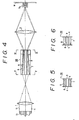
- reference numeral 33a denotes a cylindrical sleeve member whose inside surface is mirror-finished to cause reflection. Further, inside the sleeve member 33a, there is mounted concentrically a conical mirror 33b whose outer peripheral surface is mirror-finished. The sleeve member 33a having a reflective inside surface and the mirror 33b constitutes a scope 33. Further, reference numeral 1 denotes. a beam focussing lens installed on the side of the inlet of the scope 33, and 2 an image forming lens installed on the side of the outlet of the scope 33.
- the beam focussing lens 1 and the image forming lens 2 are located so that their respective optical axes are aligned with the central axis of .-the sleeve member of the scope 33.
- Reference numeral 11 denotes incident laser beams having an uneven energy distribution.
- a characteristic feature of this sixth embodiment resides in that, as mentioned above, the conical mirror 33b is merely concentrically disposed in the sleeve member 33a having a reflective inside surface in order to obtain laser beams of a ring mode, and there is no driving unit so that the stability of the laser beams having a uniform energy distribution thus formed can be improved significantly.
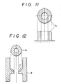
- Figure 12 shows laser hardening as one example of applications of the apparatus according to the present invention wherein laser beams of a ring mode are applied to the surface of a seat.
- a softening layer joint
Landscapes
- Physics & Mathematics (AREA)
- Optics & Photonics (AREA)
- General Physics & Mathematics (AREA)
- Engineering & Computer Science (AREA)
- Plasma & Fusion (AREA)
- Mechanical Engineering (AREA)
- Laser Beam Processing (AREA)
- Lenses (AREA)
Abstract
Applications Claiming Priority (4)
| Application Number | Priority Date | Filing Date | Title |
|---|---|---|---|
| JP158844/86 | 1986-07-08 | ||
| JP61158844A JPS6316893A (ja) | 1986-07-08 | 1986-07-08 | リングモ−ド成形装置 |
| JP177666/86 | 1986-07-30 | ||
| JP61177666A JPS6336991A (ja) | 1986-07-30 | 1986-07-30 | レ−ザビ−ム成形装置 |
Publications (3)
| Publication Number | Publication Date |
|---|---|
| EP0282593A1 true EP0282593A1 (fr) | 1988-09-21 |
| EP0282593A4 EP0282593A4 (fr) | 1989-01-24 |
| EP0282593B1 EP0282593B1 (fr) | 1993-09-15 |
Family
ID=26485842
Family Applications (1)
| Application Number | Title | Priority Date | Filing Date |
|---|---|---|---|
| EP19870904116 Expired - Lifetime EP0282593B1 (fr) | 1986-07-08 | 1987-06-25 | Appareil formant un faisceau laser |
Country Status (3)
| Country | Link |
|---|---|
| EP (1) | EP0282593B1 (fr) |
| DE (1) | DE3787463T2 (fr) |
| WO (1) | WO1988000108A1 (fr) |
Cited By (21)
| Publication number | Priority date | Publication date | Assignee | Title |
|---|---|---|---|---|
| FR2643258A1 (fr) * | 1989-02-17 | 1990-08-24 | Mezhotraslevoi N Tekhn | Dispositif pour le traitement chirurgical de l'ametropie |
| WO1991004829A1 (fr) * | 1989-10-06 | 1991-04-18 | B.V. Optische Industrie 'de Oude Delft' | Dispositif fournissant un faisceau de rayonnement laser a distribution d'energie homogene |
| WO1996005937A1 (fr) * | 1994-08-23 | 1996-02-29 | Fraunhofer-Gesellschaft zur Förderung der angewandten Forschung e.V. | Dispositif de plaquage |
| WO1998022845A1 (fr) * | 1996-11-22 | 1998-05-28 | Cogent Light Technologies, Inc. | Procede de couplage optique de fibre optique simple a faisceau multifibre ameliorant l'uniformite de champ et le rendement du couplage |
| EP0881514A1 (fr) * | 1997-05-30 | 1998-12-02 | Lasag Ag | Elément optique de couplage pour confiner spatialement et homogénéiser un faisceau ayant une grande ouverture |
| DE4111876C2 (de) * | 1990-04-19 | 2001-08-30 | Matsushita Electric Works Ltd | Verfahren zum Fügen von Metallteilen mit einem Energiestrahl |
| US6377336B1 (en) | 1991-09-11 | 2002-04-23 | Nikon Corporation | Projection exposure apparatus |
| US6636293B1 (en) | 1990-08-21 | 2003-10-21 | Nikon Corporation | Exposure method and apparatus having a decreased light intensity distribution |
| US6665050B2 (en) | 1990-11-15 | 2003-12-16 | Nikon Corporation | Projection exposure methods using difracted light with increased intensity portions spaced from the optical axis |
| US6710855B2 (en) | 1990-11-15 | 2004-03-23 | Nikon Corporation | Projection exposure apparatus and method |
| WO2004107016A3 (fr) * | 2003-05-27 | 2005-01-27 | Hentze Lissotschenko Patentver | Dispositif pour convertir un faisceau lumineux |
| DE10339636A1 (de) * | 2003-08-28 | 2005-03-24 | Hentze-Lissotschenko Patentverwaltungs Gmbh & Co.Kg | Verfahren und Vorrichtung zum simultanen Laserschweißen |
| US6885433B2 (en) | 1990-11-15 | 2005-04-26 | Nikon Corporation | Projection exposure apparatus and method |
| US6897942B2 (en) | 1990-11-15 | 2005-05-24 | Nikon Corporation | Projection exposure apparatus and method |
| US6967710B2 (en) | 1990-11-15 | 2005-11-22 | Nikon Corporation | Projection exposure apparatus and method |
| EP1793278A3 (fr) * | 2005-12-02 | 2007-12-05 | ASML Netherlands B.V. | Système d'illumination |
| US7656504B1 (en) | 1990-08-21 | 2010-02-02 | Nikon Corporation | Projection exposure apparatus with luminous flux distribution |
| WO2014060337A1 (fr) * | 2012-10-18 | 2014-04-24 | Limo Patentverwaltung Gmbh & Co. Kg | Dispositif d'exposition d'une face interne d'un cylindre à une lumière et équipement de transformation de rayonnement pour un tel dispositif |
| EP2724812A1 (fr) * | 2012-10-24 | 2014-04-30 | JENOPTIK Automatisierungstechnik GmbH | Dispositif permettant de relier deux parties de pièce ayant des zones de propriétés différentes au moyen de soudage laser par transparence et un homogénéiseur |
| EP3138650A1 (fr) * | 2015-09-03 | 2017-03-08 | Ewm Ag | Dispositif et procede de soudage a l'arc ou de brasure a l'arc a l'aide d'une electrode fusible |
| US11052485B2 (en) * | 2016-02-24 | 2021-07-06 | Jenoptik Automatisierungstechnik Gmbh | Annular laser transmission seam welding device |
Families Citing this family (6)
| Publication number | Priority date | Publication date | Assignee | Title |
|---|---|---|---|---|
| GB9019123D0 (en) * | 1990-09-01 | 1990-10-17 | Fisons Plc | Analytical device |
| EP0724498B1 (fr) * | 1993-09-30 | 1997-12-29 | Cymer, Inc. | Procedes et appareil ameliorant l'illumination de masques plein champ |
| ATE328698T1 (de) * | 2003-08-21 | 2006-06-15 | Leister Process Tech | Verfahren und vorrichtung zum simultanen erwärmen von materialien |
| US20160327802A1 (en) * | 2015-05-08 | 2016-11-10 | Synrad, Inc. | Waveguide beam conditioning for a high powered laser |
| CN110058335A (zh) * | 2019-04-30 | 2019-07-26 | 西安炬光科技股份有限公司 | 光学元件、治疗仪和光斑变换的实现方法 |
| CN111070700B (zh) * | 2019-12-20 | 2022-01-18 | 浙江舜宇智领技术有限公司 | 激光焊接治具 |
Family Cites Families (6)
| Publication number | Priority date | Publication date | Assignee | Title |
|---|---|---|---|---|
| US3947093A (en) * | 1973-06-28 | 1976-03-30 | Canon Kabushiki Kaisha | Optical device for producing a minute light beam |
| US3972599A (en) * | 1974-09-16 | 1976-08-03 | Caterpillar Tractor Co. | Method and apparatus for focussing laser beams |
| JPS59150684A (ja) * | 1983-02-18 | 1984-08-28 | Hitachi Ltd | レ−ザ加工装置 |
| US4547044A (en) * | 1983-03-31 | 1985-10-15 | International Business Machines Corporation | Beam-folding wedge tunnel |
| US4564736A (en) * | 1984-05-07 | 1986-01-14 | General Electric Company | Industrial hand held laser tool and laser system |
| JPS61103693A (ja) * | 1984-10-24 | 1986-05-22 | Hitachi Ltd | レ−ザ加工機 |
-
1987
- 1987-06-25 EP EP19870904116 patent/EP0282593B1/fr not_active Expired - Lifetime
- 1987-06-25 WO PCT/JP1987/000420 patent/WO1988000108A1/fr not_active Ceased
- 1987-06-25 DE DE87904116T patent/DE3787463T2/de not_active Expired - Fee Related
Cited By (32)
| Publication number | Priority date | Publication date | Assignee | Title |
|---|---|---|---|---|
| FR2643258A1 (fr) * | 1989-02-17 | 1990-08-24 | Mezhotraslevoi N Tekhn | Dispositif pour le traitement chirurgical de l'ametropie |
| WO1991004829A1 (fr) * | 1989-10-06 | 1991-04-18 | B.V. Optische Industrie 'de Oude Delft' | Dispositif fournissant un faisceau de rayonnement laser a distribution d'energie homogene |
| DE4111876C2 (de) * | 1990-04-19 | 2001-08-30 | Matsushita Electric Works Ltd | Verfahren zum Fügen von Metallteilen mit einem Energiestrahl |
| US7656504B1 (en) | 1990-08-21 | 2010-02-02 | Nikon Corporation | Projection exposure apparatus with luminous flux distribution |
| US6636293B1 (en) | 1990-08-21 | 2003-10-21 | Nikon Corporation | Exposure method and apparatus having a decreased light intensity distribution |
| US6704092B2 (en) | 1990-11-15 | 2004-03-09 | Nikon Corporation | Projection exposure method and apparatus that produces an intensity distribution on a plane substantially conjugate to a projection optical system pupil plane |
| US6967710B2 (en) | 1990-11-15 | 2005-11-22 | Nikon Corporation | Projection exposure apparatus and method |
| US6897942B2 (en) | 1990-11-15 | 2005-05-24 | Nikon Corporation | Projection exposure apparatus and method |
| US6885433B2 (en) | 1990-11-15 | 2005-04-26 | Nikon Corporation | Projection exposure apparatus and method |
| US6710855B2 (en) | 1990-11-15 | 2004-03-23 | Nikon Corporation | Projection exposure apparatus and method |
| US6665050B2 (en) | 1990-11-15 | 2003-12-16 | Nikon Corporation | Projection exposure methods using difracted light with increased intensity portions spaced from the optical axis |
| US6864959B2 (en) | 1991-09-11 | 2005-03-08 | Nikon Corporation | Projection exposure apparatus |
| US6392740B1 (en) | 1991-09-11 | 2002-05-21 | Nikon Corporation | Projection exposure apparatus |
| US6710854B2 (en) | 1991-09-11 | 2004-03-23 | Nikon Corporation | Projection exposure apparatus |
| US6377336B1 (en) | 1991-09-11 | 2002-04-23 | Nikon Corporation | Projection exposure apparatus |
| US5886313A (en) * | 1994-08-23 | 1999-03-23 | Fraunhofer-Gesellschaft Zur Foerderung Der Angewandten Forschung E.V. | Laser diode array device for bonding metal plates |
| WO1996005937A1 (fr) * | 1994-08-23 | 1996-02-29 | Fraunhofer-Gesellschaft zur Förderung der angewandten Forschung e.V. | Dispositif de plaquage |
| WO1998022845A1 (fr) * | 1996-11-22 | 1998-05-28 | Cogent Light Technologies, Inc. | Procede de couplage optique de fibre optique simple a faisceau multifibre ameliorant l'uniformite de champ et le rendement du couplage |
| EP0881514A1 (fr) * | 1997-05-30 | 1998-12-02 | Lasag Ag | Elément optique de couplage pour confiner spatialement et homogénéiser un faisceau ayant une grande ouverture |
| WO2004107016A3 (fr) * | 2003-05-27 | 2005-01-27 | Hentze Lissotschenko Patentver | Dispositif pour convertir un faisceau lumineux |
| DE10339636A1 (de) * | 2003-08-28 | 2005-03-24 | Hentze-Lissotschenko Patentverwaltungs Gmbh & Co.Kg | Verfahren und Vorrichtung zum simultanen Laserschweißen |
| DE10339636B4 (de) * | 2003-08-28 | 2013-02-07 | Limo Patentverwaltung Gmbh & Co. Kg | Verfahren und Vorrichtung zum simultanen Laserschweißen |
| EP1793278A3 (fr) * | 2005-12-02 | 2007-12-05 | ASML Netherlands B.V. | Système d'illumination |
| CN101013267B (zh) * | 2005-12-02 | 2011-07-27 | Asml荷兰有限公司 | 照明系统 |
| US8159651B2 (en) | 2005-12-02 | 2012-04-17 | Asml Holding N.V. | Illumination system coherence remover with a series of partially reflective surfaces |
| US8164740B2 (en) | 2005-12-02 | 2012-04-24 | Asml Holding N.V. | Illumination system coherence remover with two sets of stepped mirrors |
| WO2014060337A1 (fr) * | 2012-10-18 | 2014-04-24 | Limo Patentverwaltung Gmbh & Co. Kg | Dispositif d'exposition d'une face interne d'un cylindre à une lumière et équipement de transformation de rayonnement pour un tel dispositif |
| US9798047B2 (en) | 2012-10-18 | 2017-10-24 | Limo Patentverwaltung Gmbh & Co. Kg | Device for applying light to an inner surface of a cylinder and beam transformation device for such a device |
| EP2724812A1 (fr) * | 2012-10-24 | 2014-04-30 | JENOPTIK Automatisierungstechnik GmbH | Dispositif permettant de relier deux parties de pièce ayant des zones de propriétés différentes au moyen de soudage laser par transparence et un homogénéiseur |
| US9321127B2 (en) | 2012-10-24 | 2016-04-26 | Jenoptik Automatisierungstechnik Gmbh | Apparatus for joining two workpiece parts having regions with different characteristics by means of through-transmission welding |
| EP3138650A1 (fr) * | 2015-09-03 | 2017-03-08 | Ewm Ag | Dispositif et procede de soudage a l'arc ou de brasure a l'arc a l'aide d'une electrode fusible |
| US11052485B2 (en) * | 2016-02-24 | 2021-07-06 | Jenoptik Automatisierungstechnik Gmbh | Annular laser transmission seam welding device |
Also Published As
| Publication number | Publication date |
|---|---|
| DE3787463T2 (de) | 1994-04-28 |
| WO1988000108A1 (fr) | 1988-01-14 |
| EP0282593B1 (fr) | 1993-09-15 |
| DE3787463D1 (de) | 1993-10-21 |
| EP0282593A4 (fr) | 1989-01-24 |
Similar Documents
| Publication | Publication Date | Title |
|---|---|---|
| EP0282593A1 (fr) | Appareil formant un faisceau laser | |
| US5684642A (en) | Optical transmission system and light radiating method | |
| CA2037063C (fr) | Appareil optique d'usinage | |
| US5080474A (en) | Laser beam shaping device | |
| US5594831A (en) | Beam machining device with reflector comprised of arcs of confocal ellipses | |
| KR100206095B1 (ko) | 레이저 집광방법 및 장치 | |
| JPH07218709A (ja) | スーパーゾーンホログラフミラー | |
| US5285320A (en) | Mirror for changing the geometrical form of a light beam | |
| US5574601A (en) | Optical beam expander | |
| JPH11501738A (ja) | 反射光学付きレーザー走査装置 | |
| JP2000005892A (ja) | レーザ加工方法 | |
| JPH0961610A (ja) | バイナリーオプティクス及びそれを用いた集光光学系並びにレーザ加工装置 | |
| CN114728372B (zh) | 借助轴锥镜的射束成形对工件进行激光焊接的方法以及光学设备 | |
| EP0645648A1 (fr) | Dispositif destine a etre utilise dans le traitement par faisceaux de lumiere | |
| CN217982010U (zh) | 一种增材制造设备的光路系统 | |
| CN120233541A (zh) | 一种产生点环光的旋转镜扫描光路系统及其控制方法 | |
| WO1997006462A1 (fr) | Systeme optique rotatif pour dispositif d'usinage a laser | |
| JP2800006B2 (ja) | レーザ装置 | |
| JPS6121193Y2 (fr) | ||
| JP2002316289A (ja) | レーザ加工装置 | |
| JPH0698508B2 (ja) | 光ビ−ム加工装置 | |
| JP3055312B2 (ja) | レーザビーム均一照射光学系 | |
| JP3479197B2 (ja) | レーザ装置 | |
| RU2032195C1 (ru) | Сканатор мощного лазерного излучения | |
| GB2316187A (en) | Laser optical fibre transmission system with adjustable angle of incidence |
Legal Events
| Date | Code | Title | Description |
|---|---|---|---|
| PUAI | Public reference made under article 153(3) epc to a published international application that has entered the european phase |
Free format text: ORIGINAL CODE: 0009012 |
|
| 17P | Request for examination filed |
Effective date: 19880303 |
|
| AK | Designated contracting states |
Kind code of ref document: A1 Designated state(s): DE FR GB |
|
| A4 | Supplementary search report drawn up and despatched |
Effective date: 19890124 |
|
| 17Q | First examination report despatched |
Effective date: 19900321 |
|
| GRAA | (expected) grant |
Free format text: ORIGINAL CODE: 0009210 |
|
| AK | Designated contracting states |
Kind code of ref document: B1 Designated state(s): DE FR GB |
|
| PG25 | Lapsed in a contracting state [announced via postgrant information from national office to epo] |
Ref country code: FR Effective date: 19930915 |
|
| REF | Corresponds to: |
Ref document number: 3787463 Country of ref document: DE Date of ref document: 19931021 |
|
| EN | Fr: translation not filed | ||
| PLBE | No opposition filed within time limit |
Free format text: ORIGINAL CODE: 0009261 |
|
| STAA | Information on the status of an ep patent application or granted ep patent |
Free format text: STATUS: NO OPPOSITION FILED WITHIN TIME LIMIT |
|
| 26N | No opposition filed | ||
| PGFP | Annual fee paid to national office [announced via postgrant information from national office to epo] |
Ref country code: GB Payment date: 19950614 Year of fee payment: 9 |
|
| PGFP | Annual fee paid to national office [announced via postgrant information from national office to epo] |
Ref country code: DE Payment date: 19950617 Year of fee payment: 9 |
|
| PG25 | Lapsed in a contracting state [announced via postgrant information from national office to epo] |
Ref country code: GB Effective date: 19960625 |
|
| GBPC | Gb: european patent ceased through non-payment of renewal fee |
Effective date: 19960625 |
|
| PG25 | Lapsed in a contracting state [announced via postgrant information from national office to epo] |
Ref country code: DE Effective date: 19970301 |