EP0282626A2 - Valve pour chambre pneumatique d'amortisseur hydropneumatique - Google Patents
Valve pour chambre pneumatique d'amortisseur hydropneumatique Download PDFInfo
- Publication number
- EP0282626A2 EP0282626A2 EP87108659A EP87108659A EP0282626A2 EP 0282626 A2 EP0282626 A2 EP 0282626A2 EP 87108659 A EP87108659 A EP 87108659A EP 87108659 A EP87108659 A EP 87108659A EP 0282626 A2 EP0282626 A2 EP 0282626A2
- Authority
- EP
- European Patent Office
- Prior art keywords
- valve
- head
- piston
- groove
- threaded
- Prior art date
- Legal status (The legal status is an assumption and is not a legal conclusion. Google has not performed a legal analysis and makes no representation as to the accuracy of the status listed.)
- Withdrawn
Links
- 230000035939 shock Effects 0.000 title description 7
- 239000006096 absorbing agent Substances 0.000 title description 6
- 230000002093 peripheral effect Effects 0.000 claims description 4
- 230000000717 retained effect Effects 0.000 claims description 3
- 238000007789 sealing Methods 0.000 abstract description 6
- 230000000694 effects Effects 0.000 abstract description 2
- 239000002184 metal Substances 0.000 description 9
- 239000012528 membrane Substances 0.000 description 5
- 230000007423 decrease Effects 0.000 description 1
- 239000000203 mixture Substances 0.000 description 1
- 230000000149 penetrating effect Effects 0.000 description 1
- 239000000725 suspension Substances 0.000 description 1
Images
Classifications
-
- F—MECHANICAL ENGINEERING; LIGHTING; HEATING; WEAPONS; BLASTING
- F15—FLUID-PRESSURE ACTUATORS; HYDRAULICS OR PNEUMATICS IN GENERAL
- F15B—SYSTEMS ACTING BY MEANS OF FLUIDS IN GENERAL; FLUID-PRESSURE ACTUATORS, e.g. SERVOMOTORS; DETAILS OF FLUID-PRESSURE SYSTEMS, NOT OTHERWISE PROVIDED FOR
- F15B1/00—Installations or systems with accumulators; Supply reservoir or sump assemblies
- F15B1/02—Installations or systems with accumulators
- F15B1/04—Accumulators
- F15B1/08—Accumulators using a gas cushion; Gas charging devices; Indicators or floats therefor
-
- F—MECHANICAL ENGINEERING; LIGHTING; HEATING; WEAPONS; BLASTING
- F16—ENGINEERING ELEMENTS AND UNITS; GENERAL MEASURES FOR PRODUCING AND MAINTAINING EFFECTIVE FUNCTIONING OF MACHINES OR INSTALLATIONS; THERMAL INSULATION IN GENERAL
- F16F—SPRINGS; SHOCK-ABSORBERS; MEANS FOR DAMPING VIBRATION
- F16F9/00—Springs, vibration-dampers, shock-absorbers, or similarly-constructed movement-dampers using a fluid or the equivalent as damping medium
- F16F9/32—Details
- F16F9/43—Filling or drainage arrangements, e.g. for supply of gas
-
- F—MECHANICAL ENGINEERING; LIGHTING; HEATING; WEAPONS; BLASTING
- F16—ENGINEERING ELEMENTS AND UNITS; GENERAL MEASURES FOR PRODUCING AND MAINTAINING EFFECTIVE FUNCTIONING OF MACHINES OR INSTALLATIONS; THERMAL INSULATION IN GENERAL
- F16K—VALVES; TAPS; COCKS; ACTUATING-FLOATS; DEVICES FOR VENTING OR AERATING
- F16K15/00—Check valves
- F16K15/20—Check valves specially designed for inflatable bodies, e.g. tyres
-
- F—MECHANICAL ENGINEERING; LIGHTING; HEATING; WEAPONS; BLASTING
- F15—FLUID-PRESSURE ACTUATORS; HYDRAULICS OR PNEUMATICS IN GENERAL
- F15B—SYSTEMS ACTING BY MEANS OF FLUIDS IN GENERAL; FLUID-PRESSURE ACTUATORS, e.g. SERVOMOTORS; DETAILS OF FLUID-PRESSURE SYSTEMS, NOT OTHERWISE PROVIDED FOR
- F15B2201/00—Accumulators
- F15B2201/20—Accumulator cushioning means
- F15B2201/205—Accumulator cushioning means using gas
-
- F—MECHANICAL ENGINEERING; LIGHTING; HEATING; WEAPONS; BLASTING
- F15—FLUID-PRESSURE ACTUATORS; HYDRAULICS OR PNEUMATICS IN GENERAL
- F15B—SYSTEMS ACTING BY MEANS OF FLUIDS IN GENERAL; FLUID-PRESSURE ACTUATORS, e.g. SERVOMOTORS; DETAILS OF FLUID-PRESSURE SYSTEMS, NOT OTHERWISE PROVIDED FOR
- F15B2201/00—Accumulators
- F15B2201/30—Accumulator separating means
- F15B2201/315—Accumulator separating means having flexible separating means
- F15B2201/3151—Accumulator separating means having flexible separating means the flexible separating means being diaphragms or membranes
-
- F—MECHANICAL ENGINEERING; LIGHTING; HEATING; WEAPONS; BLASTING
- F15—FLUID-PRESSURE ACTUATORS; HYDRAULICS OR PNEUMATICS IN GENERAL
- F15B—SYSTEMS ACTING BY MEANS OF FLUIDS IN GENERAL; FLUID-PRESSURE ACTUATORS, e.g. SERVOMOTORS; DETAILS OF FLUID-PRESSURE SYSTEMS, NOT OTHERWISE PROVIDED FOR
- F15B2201/00—Accumulators
- F15B2201/40—Constructional details of accumulators not otherwise provided for
- F15B2201/41—Liquid ports
-
- F—MECHANICAL ENGINEERING; LIGHTING; HEATING; WEAPONS; BLASTING
- F15—FLUID-PRESSURE ACTUATORS; HYDRAULICS OR PNEUMATICS IN GENERAL
- F15B—SYSTEMS ACTING BY MEANS OF FLUIDS IN GENERAL; FLUID-PRESSURE ACTUATORS, e.g. SERVOMOTORS; DETAILS OF FLUID-PRESSURE SYSTEMS, NOT OTHERWISE PROVIDED FOR
- F15B2201/00—Accumulators
- F15B2201/40—Constructional details of accumulators not otherwise provided for
- F15B2201/415—Gas ports
- F15B2201/4155—Gas ports having valve means
Definitions
- the subject of the present invention is a valve for a pneumatic hydropneumatic damper chamber intended to replace the original plug, comprising a threaded body provided with a threaded circular head, the lower face of which has a groove in which a gasket is housed. sealing and having an axial passage containing a valve.
- the suspension of certain motor cars comprises hydropneumatic shock absorbers consisting of a metal enclosure partially occupied by a tight elastic enclosure containing a gas under pressure, the metallic enclosure being connected to a single-acting hydraulic cylinder system through a throttle.
- the elastic inner enclosure is partially constituted by an elastic membrane having at its upper part an opening closed by a plug which serves at the same time for fixing the inner enclosure by means of a metal cup.
- the pressure in the pneumatic chamber decreases, mainly when the shock absorber has to absorb large shocks.
- a ball inflated in advance often does not have, after a certain period of storage, the original calibration during assembly. Therefore, at the time of assembly it often happens that the spheres, which are mounted in pairs for reasons of comfort and safety, no longer have the same inflation.
- a pair of spheres, one of which is at a pressure of 50 bars and the other at 40 bars causes an imbalance in the car. Pressure loss can have more serious consequences. Indeed, when the volume of the pneumatic chamber becomes too small, the lower part of its membrane can, in the event of an impact, come into contact with the metal cup and then risk being pierced.
- the object of the present invention is to replace the original plug of a pneumatic hydropneumatic damper chamber with a valve occupying approximately the same space as the original plug, ensuring a seal approximately equal to that of the original plug and offering great security.
- valve head has a height less than the length of the threaded body and that the axial passage is tapped in this head, this tapped part being followed by a conical seat followed by 'a strange itself followed by a valve seat for a valve valve consisting of a stud provided with a rod engaging in the throttle and surrounded by an O-ring seal, the valve being retained otherwise part by a screw screwed to the other end of said body and pierced with an axial hole, the valve being closed, when not in use, by a plug screwed into said threaded axial passage and having a conical end which is applied to said conical seat.
- the head of the valve is hardly greater than the height of the head of the original plug, so that it does not form an unacceptable and dangerous projection above the sphere.
- the valve is closed by a plug embedded in the head, preventing untimely use of the valve and ensuring a second sealed closure, in addition to the sealed closure provided by the valve.
- the head of the valve is furthermore preferably provided with means allowing the fixing of a special valve connected by a tube to a source of compressed gas.
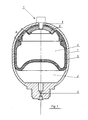
- the known hydropneumatic damper shown in Figure 1 consists of a metal enclosure 1 containing on the one hand a hydraulic chamber 2 communicating by a throttle 3 with a hydraulic cylinder system with single effect not shown, and a pneumatic chamber 4 limited by an elastic membrane 5 closed and held against the wall of the enclosure 1 by a metal cup 6.
- This cup 6 is held by the threaded part of a valve 7 passing through the metal enclosure 1 through an orifice 8.
- the valve body 7 comprises a threaded circular head 9 and a threaded part 10 screwed into the cup 6.
- the height of the head 9 is less than the length of the threaded part 10.
- the valve body is traversed by an axial passage whose part 11 located in the head is tapped to receive a metal plug 12 provided with an internal hex.
- the threaded part 11 ends in a conical seat 14 whose surface is polished. On this seat 14 is applied the conical end 15 of the plug 12 to provide an additional tight closure.
- the axial passage consists of a constriction 16 followed by a plane valve seat 17 against which the seal gasket 19 of a valve 18 is applied, consisting of a hexagonal stud provided with a rod 20 penetrating with clearance in the constriction 16 and carrying the O-ring 19.
- the hexagonal section ensures the gas passge.
- the valve 18 is retained in its bore 21 by a screw 22 screwed into the valve body and provided with an axial hole 23.
- the periphery of the head 9 is threaded so as to allow the fixing by screwing of a plastic cap, in the form of a cylindrical cap.
- the seal between the valve head 9 and the metal enclosure 1 is also ensured by a seal sheath 24 housed in a groove provided in the base of the head 9.
- valve is therefore doubly protected by the plug 12 which provides additional sealing, and by the cap. These two elements must be removed in order to be able to introduce a compressed gas into the enclosure.
- the head 9 is further provided with a peripheral groove 25 intended for fixing a valve for connecting the valve 7 to a source of compressed gas.
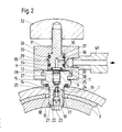
- This connection valve comprises a body 26 of hexagonal prismatic shape, the base of which is provided with a T-shaped groove 27 in which the valve head 9 can be engaged by its I-profile, as shown in FIG. 2.
- the valve body 26 has a central bore 29 in which is housed a piston 30 secured to a threaded portion 31 screwed into a threaded passage of the body 26 and secured to a handle or handle 32 allowing the piston to be moved by screwing or unscrewing its threaded part 31.
- This piston 30 is provided with two O-rings 33 and 34 ensuring the sealing of the piston between its linings, this middle part of the piston having a peripheral groove 35 communicating with a radial duct 36 opening into an axial duct 37 opening in turn on the underside of the piston 30 in a recess bounded by an annular groove in which is housed a seal gasket 38 constituted by an O-ring, the inner diameter of which is measured slightly larger than the diameter of the valve passage 11.
- the valve body 26 is provided with a radial hole 39 to which is connected the end of a tube 40 connected to a source of compressed gas.
- valve is fixed to the valve 7 as shown in FIG. 2 then the piston 30 is lowered by turning the handle 32.
- the O-ring seal 38 then comes to apply against the upper face of the head 9, around the passage 11.
- the groove 35 of the piston 30 comes into communication with the hole 39, putting the source of compressed gas into communication with the valve 7 Note that the piston 30 simultaneously secures the valve to the valve head 9.
Landscapes
- Engineering & Computer Science (AREA)
- General Engineering & Computer Science (AREA)
- Mechanical Engineering (AREA)
- Physics & Mathematics (AREA)
- Fluid Mechanics (AREA)
- Fluid-Damping Devices (AREA)
- Lift Valve (AREA)
Abstract
Description
- La présente invention a pour objet une valve pour chambre pneumatique d'amortisseur hydropneumatique destinée à remplacer le bouchon d'origine, comprenant un corps fileté muni d'une tête circulaire filetée dont la face inférieure présente une gorge dans laquelle est logée une garniture d'étanchéité et présentant un passage axial contenant un clapet.
- La suspension de certaines voitures automobiles comprend des amortisseurs hydropneumatiques constitués d'une enceinte métallique occupée en partie par une enceinte élastique étanche contenant un gaz sous pression, l'enceinte métallique étant reliée à un système à vérin hydraulique à simple effet à travers un étrangleur. L'enceinte intérieure élastique est constituée partiellement par une membrane élastique présentant à sa partie supérieure une ouverture fermée par un bouchon qui sert en même temps à la fixation de l'enceinte intérieure au moyen d'une coupelle métallique. Malgré tout le soin apporté au montage de ces amortisseurs, des microfuites, en particulier au niveau de la zone d'étanchéité entre la membrane et la coupelle métallique et à travers la membrane, sont toujours possibles. Le fait que l'enceinte pneumatique est remplie par du gaz à très haute pression favorise encore ces microfuites. Avec le temps, la pression dans la chambre pneumatique diminue, principalement lorsque l'amortisseur doit absorber de grands chocs. En outre, une sphère gonflée à l'avance n'a souvent plus, après une certaine période de stockage, le tarage d'origine lors du montage. De ce fait, au moment du montage il arrive souvent que les sphères, qui sont montées par paires pour des raisons de confort et de sécurité, n'ont plus le même gonflage. Ainsi, par exemple, une paire de sphères dont l'une est à une pression de 50 bars et l'autre à 40 bars provoque un déséquilibre de la voiture. Une perte de pression peut avoir des conséquences plus graves. En effet, lorsque le volume de la chambre pneumatique devient trop petit, la partie inférieure de sa membrane peut, en cas de choc, arriver en contact avec la coupelle métallique et risque alors de se percer. Si la membrane est percée, l'huile de la chambre hydralique et le gaz de la chambre pneumatique se mélangent et l'amortisseur perd toute son efficacité. Dans tous les cas, jusqu'ici, toute sphère d'amortisseur ayant subi une perte notable de pression devait être remplacée.
- Pour pallier à ces inconvénients, on a déjà proposé de remplacer le bouchon d'origine de la sphère par une valve à bille, mais la valve utilisée assure une étanchéité et une sécurité insuffisantes. Elle peut notamment être démontée ou actionnée par une personne non compétente.
- La présente invention a pour but de remplacer le bouchon d'origine d'une chambre pneumatique d'amortisseur hydropneumatique par une valve occupant approximativement le même espace que le bouchon d'origine, assurant une étanchéité approximativement égale à celle du bouchon d'origine et offrant une grande sécurité.
- La valve selon l'invention est caractérisée par le fait que la tête de la valve présente une hauteur inférieure à la longueur du corps fileté et que le passage axial est taraudé dans cette tête, cette partie taraudée étant suivie d'un siège conique suivi d'un étrang lement lui-même suivi d'un siège de clapet pour un clapet de valve constitué d'un plot muni d'une tige s'engageant dans l'étranglement et entourée d'une garniture de joint torique, le clapet étant retenue d'autre part par une vis vissée à l'autre extrémité dudit corps et percée d'un trou axial, la valve étant fermée, en période de non utilisation, par un bouchon vissé dans ledit passage axial taraudé et présentant une extrémité conique venant s'appliquer sur ledit siège conique.
- La tête de la valve n'est guère supérieure à la hauteur de la tête du bouchon d'origine, de telle sorte qu'il ne se forme pas de saillie inacceptable et dangereuse au-dessus de la sphère. En période de non-utilisation, la valve est fermée par un bouchon noyé dans la tête, empêchant l'utilisation intempestive de la valve et assurant une seconde fermeture étanche, en plus de la fermeture étanche assurée par le clapet.
- La tête de la valve est en outre de préférence munie de moyens permettant la fixation d'une vanne spéciale reliée par un tube à une source de gaz comprimé.
- Le dessin annexé représente, à titre d'exemple, une forme d'exécution de l'invention.
- La figure 1 est une vue en coupe d'un amortisseur hydropneumatique connu muni d'une valve selon l'invention.
- La figure 2 est une vue en coupe axiale de la valve.
- L'amortisseur hydropneumatique connu représenté à la figure 1 est constitué d'une enceinte métallique 1 contenant d'une part une chambre hydraulique 2 communiquant par un étrangleur 3 avec un système de vérin hydraulique à simple effet non représenté, et une chambre pneumatique 4 limitée par une membrane élastique 5 fermée et maintenue contre la paroi de l'enceinte 1 par une coupelle métallique 6. Cette coupelle 6 est maintenue par la partie filetée d'une valve 7 traversant l'enceinte métallique 1 par un orifice 8.
- Le corps de la valve 7 comprend une tête circulaire filetée 9 et une partie filetée 10 vissée dans la coupelle 6. La hauteur de la tête 9 est inférieure à la longueur de la partie filetée 10. Le corps de valve est traversé par un passage axial dont la partie 11 située dans la tête est taraudée pour recevoir un bouchon métallique 12 muni d'un six-pans intérieur. La partie taraudée 11 se termine par un siège conique 14 dont la surface est polie. Sur ce siège 14 vient s'appliquer l'extrémité conique 15 du bouchon 12 pour assurer une fermeture étanche supplémentaire. En-dessous du siège 14, le passage axial est constitué par un étranglement 16 suivi d'un siège de valve plan 17 contre lequel vient s'appliquer la garniture de joint 19 d'un clapet 18 constitué d'un plot hexagonal muni d'une tige 20 pénétrant avec jeu dans l'étranglement 16 et portant la garniture torique 19. La section hexagonale assure le passge du gaz. Le clapet 18 est retenu dans son alésage 21 par une vis 22 vissée dans le corps de valve et munie d'un trou axial 23.
- Le pourtour de la tête 9 est fileté de manière à permettre la fixation par vissage d'un capuchon en matière synthétique, en forme de calotte cylindrique. L'étanchéité entre la tête de valve 9 et l'enceinte métallique 1 est en outre assurée par une garniture d'étan chéité 24 logée dans une rainure prévue dans la base de la tête 9.
- La valve est donc doublement protégée par le bouchon 12 qui assure une étanchéité complémentaire, et par le capuchon. Il est nécessaire d'enlever ces deux éléments pour pouvoir introduire un gaz comprimé dans l'enceinte.
- La tête 9 est en outre munie d'une gorge périphérique 25 destinée à la fixation d'une vanne de raccordement de la valve 7 à une source de gaz comprimé. Cette vanne de raccordement comprend un corps 26 de forme prismatique hexagonale dont la base est pourvue d'une rainure 27 profilée en T dans laquelle peut venir s'engager la tête de valve 9 par son profil en I, comme représenté à la figure 2. Le corps de vanne 26 présente un alésage central 29 dans lequel est logé un piston 30 solidaire d'une partie filetée 31 vissée dans un passage taraudé du corps 26 et solidaire d'une poignée ou manette 32 permettant de déplacer le piston en vissant ou dévissant sa partie filetée 31. Ce piston 30 est muni de deux garnitures toriques 33 et 34 assurant l'étanchéité du piston entre ses garnitures, cette partie médiane du piston présentant une gorge périphérique 35 communiquant avec un conduit radial 36 débouchant dans un conduit axial 37 débouchant à son tour sur la face inférieure du piston 30 dans une creusure limitée par une gorge annulaire dans laquelle est logée une garniture de joint 38 constituée par un O-ring, dont le diamètre intérieur est légèrement supérieur au diamètre du passage 11 de la valve. Le corps de valve 26 est muni d'un trou radial 39 auquel est reliée l'extrémité d'un tube 40 relié à une source de gaz comprimé.
- Pour remplir la sphère 1, on fixe la vanne à la valve 7 comme représenté à la figure 2 puis l'on fait descendre le piston 30 en tournant la poignée 32. Le joint O-ring 38 vient alors s'appliquer contre la face supérieure de la tête 9, autour du passage 11. Une fois que le joint O-ring 38 commence à être comprimé, la gorge 35 du piston 30 vient en communication avec le trou 39, mettant en communication la source de gaz comprimé avec la valve 7. On remarque que le piston 30 assure simultanément la fixation de la vanne à la tête de valve 9.
Claims (4)
Applications Claiming Priority (2)
| Application Number | Priority Date | Filing Date | Title |
|---|---|---|---|
| CH1015/87A CH670686A5 (fr) | 1987-03-18 | 1987-03-18 | |
| CH1015/87 | 1987-03-18 |
Publications (2)
| Publication Number | Publication Date |
|---|---|
| EP0282626A2 true EP0282626A2 (fr) | 1988-09-21 |
| EP0282626A3 EP0282626A3 (fr) | 1989-04-26 |
Family
ID=4200466
Family Applications (1)
| Application Number | Title | Priority Date | Filing Date |
|---|---|---|---|
| EP87108659A Withdrawn EP0282626A3 (fr) | 1987-03-18 | 1987-06-16 | Valve pour chambre pneumatique d'amortisseur hydropneumatique |
Country Status (4)
| Country | Link |
|---|---|
| EP (1) | EP0282626A3 (fr) |
| CH (1) | CH670686A5 (fr) |
| FR (1) | FR2613010B3 (fr) |
| IL (1) | IL83888A0 (fr) |
Cited By (2)
| Publication number | Priority date | Publication date | Assignee | Title |
|---|---|---|---|---|
| AT398465B (de) * | 1992-05-20 | 1994-12-27 | Isi Metallwarenfabrik Ges M B | Vorrichtung zur abgabe von gasen aus gaskapseln |
| EP0997662A1 (fr) * | 1998-10-27 | 2000-05-03 | Diebolt International, Inc. | Vanne de remplissage pour ressort à gaz |
Family Cites Families (5)
| Publication number | Priority date | Publication date | Assignee | Title |
|---|---|---|---|---|
| DE2447343A1 (de) * | 1974-10-04 | 1976-04-15 | Teves Gmbh Alfred | Anschlusskopf eines gasfuellgeraetes |
| DE2551124A1 (de) * | 1975-11-14 | 1977-05-26 | Bosch Gmbh Robert | Fuellvorrichtung fuer den gasraum eines druckbehaelters |
| DE2843605A1 (de) * | 1978-10-06 | 1980-04-17 | Fichtel & Sachs Ag | Fuell- und pruefgeraet fuer druckraeume |
| NL8402484A (nl) * | 1984-08-10 | 1986-03-03 | Koenraad Hagen | Inrichting voor het met gas onder druk vullen van een met een schroefstop afgesloten houder, in het bijzonder de gasbol van een hydraupneumatische veerinrichting. |
| CH661106A5 (fr) * | 1985-01-25 | 1987-06-30 | Emmanuel Cafiso | Valve pour chambre pneumatique d'amortisseur hydropneumatique. |
-
1987
- 1987-03-18 CH CH1015/87A patent/CH670686A5/fr not_active IP Right Cessation
- 1987-03-27 FR FR8704296A patent/FR2613010B3/fr not_active Expired
- 1987-06-16 EP EP87108659A patent/EP0282626A3/fr not_active Withdrawn
- 1987-09-14 IL IL83888A patent/IL83888A0/xx unknown
Cited By (3)
| Publication number | Priority date | Publication date | Assignee | Title |
|---|---|---|---|---|
| AT398465B (de) * | 1992-05-20 | 1994-12-27 | Isi Metallwarenfabrik Ges M B | Vorrichtung zur abgabe von gasen aus gaskapseln |
| EP0997662A1 (fr) * | 1998-10-27 | 2000-05-03 | Diebolt International, Inc. | Vanne de remplissage pour ressort à gaz |
| US6199838B1 (en) | 1998-10-27 | 2001-03-13 | Diebolt International, Inc. | Gas spring filler valve |
Also Published As
| Publication number | Publication date |
|---|---|
| IL83888A0 (en) | 1988-02-29 |
| FR2613010B3 (fr) | 1989-06-30 |
| CH670686A5 (fr) | 1989-06-30 |
| EP0282626A3 (fr) | 1989-04-26 |
| FR2613010A1 (fr) | 1988-09-30 |
Similar Documents
| Publication | Publication Date | Title |
|---|---|---|
| LU87671A1 (fr) | Robinet pour gaz comprime ou liquifie | |
| EP0010465B1 (fr) | Vanne à ouverture automatique, notamment pour des installations de protection contre l'incendie | |
| FR2687643A1 (fr) | Recipient distributeur de fluide. | |
| WO2011000839A1 (fr) | Detendeur avec obturateur et selecteur de debit | |
| FR2743353A1 (fr) | Embout de distribution de produits liquides ou pateux | |
| FR3013101A1 (fr) | Protecteur universel pour bouteille a gaz | |
| CA2312200A1 (fr) | Dispositif de fermeture automatique pour un robinet pour gaz comprimes ou liquefies | |
| WO2016009035A1 (fr) | Valve de sécurité | |
| FR2576661A3 (fr) | Valve pour chambre pneumatique d'amortisseur hydropneumatique. | |
| LU86438A1 (fr) | Robinet a membrane | |
| CH670686A5 (fr) | ||
| CA1320971C (fr) | Amortisseur a etancheite dynamique amelioree | |
| FR2631937A1 (fr) | ||
| EP0305312B1 (fr) | Dispositif monté sur une roue destiné à maintenir la pression dans un pneumatique, comprenant un réservoir d'air surcomprimé et un régulateur de pression qui déclenchera une alarme en cas de crevaison | |
| EP0428901B1 (fr) | Détendeur neutralisable | |
| EP1295056B1 (fr) | Soupape de surete pour reservoir contenant un fluide liquide sous pression tel que du gpl | |
| CH687409A5 (fr) | Valve pour chambre pneumatique d'amortisseur hydropneumatique. | |
| FR2489514A1 (fr) | Dispositif pour signaler le degonflement d'un pneumatique de vehicule et valve destinee a retenir normalement un fluide gazeux dans une enceinte | |
| LU88378A1 (fr) | Dispositif de fermeture d'une bouteille non rechargeable et adaptateurs de remplissage et de vidange à travers un tel dispositif | |
| FR2796701A1 (fr) | Soupape de surete pour enceinte etanche contenant un fluide sous pression telle un reservoir gpl | |
| FR3099063A1 (fr) | Extincteur pyrotechnique pour véhicule | |
| FR2728315A3 (fr) | Valve pour chambre pneumatique d'amortisseur hydropneumatique | |
| FR2899300A1 (fr) | Dispositif de valve de bouteille de gaz liquefie | |
| FR2498267A1 (fr) | Perfectionnements aux accumulateurs oleo-pneumatiques | |
| EP0743077B1 (fr) | Dispositif de sécurité anti haute-pression pour extincteur d'incendie |
Legal Events
| Date | Code | Title | Description |
|---|---|---|---|
| PUAI | Public reference made under article 153(3) epc to a published international application that has entered the european phase |
Free format text: ORIGINAL CODE: 0009012 |
|
| AK | Designated contracting states |
Kind code of ref document: A2 Designated state(s): AT BE CH DE ES FR GB GR IT LI LU NL SE |
|
| RBV | Designated contracting states (corrected) |
Designated state(s): AT BE DE ES FR GB GR IT LU NL SE |
|
| PUAL | Search report despatched |
Free format text: ORIGINAL CODE: 0009013 |
|
| AK | Designated contracting states |
Kind code of ref document: A3 Designated state(s): AT BE DE ES FR GB GR IT LU NL SE |
|
| 17P | Request for examination filed |
Effective date: 19890708 |
|
| 17Q | First examination report despatched |
Effective date: 19900111 |
|
| STAA | Information on the status of an ep patent application or granted ep patent |
Free format text: STATUS: THE APPLICATION IS DEEMED TO BE WITHDRAWN |
|
| 18D | Application deemed to be withdrawn |
Effective date: 19910103 |