EP0282687A2 - Furet pour l'examen de points à l'intérieur d'un tube - Google Patents
Furet pour l'examen de points à l'intérieur d'un tube Download PDFInfo
- Publication number
- EP0282687A2 EP0282687A2 EP88100068A EP88100068A EP0282687A2 EP 0282687 A2 EP0282687 A2 EP 0282687A2 EP 88100068 A EP88100068 A EP 88100068A EP 88100068 A EP88100068 A EP 88100068A EP 0282687 A2 EP0282687 A2 EP 0282687A2
- Authority
- EP
- European Patent Office
- Prior art keywords
- pipe line
- spot
- pig
- photographing
- pig body
- Prior art date
- Legal status (The legal status is an assumption and is not a legal conclusion. Google has not performed a legal analysis and makes no representation as to the accuracy of the status listed.)
- Granted
Links
Images

Classifications
-
- G—PHYSICS
- G01—MEASURING; TESTING
- G01M—TESTING STATIC OR DYNAMIC BALANCE OF MACHINES OR STRUCTURES; TESTING OF STRUCTURES OR APPARATUS, NOT OTHERWISE PROVIDED FOR
- G01M3/00—Investigating fluid-tightness of structures
- G01M3/005—Investigating fluid-tightness of structures using pigs or moles
-
- G—PHYSICS
- G01—MEASURING; TESTING
- G01N—INVESTIGATING OR ANALYSING MATERIALS BY DETERMINING THEIR CHEMICAL OR PHYSICAL PROPERTIES
- G01N2291/00—Indexing codes associated with group G01N29/00
- G01N2291/02—Indexing codes associated with the analysed material
- G01N2291/028—Material parameters
- G01N2291/02872—Pressure
-
- G—PHYSICS
- G01—MEASURING; TESTING
- G01N—INVESTIGATING OR ANALYSING MATERIALS BY DETERMINING THEIR CHEMICAL OR PHYSICAL PROPERTIES
- G01N2291/00—Indexing codes associated with group G01N29/00
- G01N2291/02—Indexing codes associated with the analysed material
- G01N2291/028—Material parameters
- G01N2291/0289—Internal structure, e.g. defects, grain size, texture
Definitions
- This invention relates to an intrapipe spot examination pig device which is travelled under pressure within a pipe line to be examined so that any defect spot, such as a corroded spot, on the inner surface of the pipe line can be examined and any subsequent counter-measure can be taken based on the result of examination.
- Various intrapipe spot examination pig devices are known to date, but they are lower in examination accuracy and it is also impossible to exactly evaluate various defect or off-normal spots on the inner surface of the pipe line.
- a contact arm is attached to an outer surface of a pig body, and the pig body can be run within the pipe line with the contact arm in contact with the inner surface of the pipe line so that an off-normal or defect spot can be recorded and that the state of the pipe line can be known as a result of measuring the pipe inner diameter.
- This pig body is travelled within the pipe line such that the contact arm per se describes a circular arc, not exactly follows the inner surface of the pipe.
- a nonlinear curve is obtained as a result of measuring the inner surface of the pie line, failing to exactly detect any off-normal or defect spot on the inner surface of the pipe line.
- a pig body is travelled within a pipe line, to be examined, with an endoscopic camera mounted thereon and a signal line is connected to this camera and brought out to an outside so that the inner surface of the pipe line can be monitored. It is, however, difficult to locate or determine the size and position of any defects on the inner surface of the pipe line.
- a battery train unit, sensor train unit, amplifier train unit for amplifying a sensor signal, recording train unit for recording an amplified output from the amplifier train unit, and so on are coupled in series to a traction train unit which has a power source.
- a train of these units is travelled within the pipe line.
- This type of train is suitable to measuring the inner surface of a long-haul large-diameter pipe line, but the manufacturing cost becomes very high if there is no train corresponding to a pipe size.
- the following type of conventional means which can measure the inner surface of a pipe line on an examination unit pulled by a wire, connected to the examination unit, by virtue of a winch or a human power so that the examination unit may be passed through a pipe line.
- This type of examination unit is very simple in operation, but is unsuitable to measuring the inner surface of a medium- or long-haul pipe line because a man power is required.
- the aforementioned examination means or devices are poor in the accuracy of examination and thus it is not possible to exactly grasp various states of the inner surface of the pipe line.
- Japanese Patent Disclosure (KOKAI) No. 60-23819 discloses an improved long-haul type pipe inner surface photographing device over the aforementioned devices or means.
- the photographing device is adapted to examine the inner state of the pipe line by photographing it, in units of several meters, with the use of a direct-view type camera or strobo unit.
- the photographing device is employed as a long-haul measuring device and as a weld spot detecting device.
- Japanese Utility Model Disclosure (KOKAI) No. 62-69108 discloses a device for measuring a pipe inner diameter with the use of an ultrasonic wave.
- the device is adapted to examine the pipe inner diameter from a transmit/receive time.
- any defect such as a corroded spot
- an intrapipe spot examination pig device which comprises: a pig body to be travelled, under pressure, within a pipe line to be examined; detecting unit mounted on the pig unit and adapted to detect a weld spot within the pipe line; a moving distance meter for measuring the distance travelled by the pig body within the pipe line; photographing unit mounted on the pig body to photograph the inner surface of the pipe line; and a control unit for controllably operating the photographing unit for a photograph to be taken relative to the inner surface.
- a means is also provided for measuring the inner diameter of the pipe line.
- the intrapipe spot examination pig device thus manufactured can photograph any spot, such as a corroded weld spot, through the switching of a photographing mode from a direct- to a side-shot mode, while locating the position of the weld spot by means of a moving distance meter.
- a pipe inner diameter measuring means which is made up of an ultrasonic wave transmitter and receiver, it can detect any abnormal or off-normal inner diameter of the pipe line. It is also possible to exactly photograph any off-normal or abnormal spot on the inner surface of the pipe line through the switching of a shot mode from a direct- to a side-view shot, while locating that spot by means of a moving distance meter.
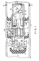
- pig body 12 is inserted into pipe line 11 (hereinafter referred to merely as a pipe line) to be examined.
- a measuring means is mounted on pig body 12 to measure various inner states of the pipe line.
- Pig body 12 can be moved, in a direction of an arrow in Fig. 1, utilizing a pressure difference created ahead and behind the pig device within the pipe line. If any abrupt bend or curve is present within the pipe line during the run of pig body 12, cushion body 13, such as urethane rubber, is provided on the head of pig body 12 so as to prevent the measuring means on the pig device from being broken due to the collision of the pig device with the abrupt bend or curve.
- a pair of sealing cups 14, 15 for pressure reception are provided outside pig body 12 such that they are located at a predetermined interval in the longitudinal direction of the pig device.
- sealing cups 14, 15 use is made of a soft, durable material, such as urethane. Even if any step is formed on the inner surface of the pipe line during the travelling of pig body 12, pig body 12 can successfully traverse the step due to the soft nature of sealing cups 14, 15. Given the pressure difference ahead and behind the pig body during the run, sealing cups 14, 15 receive that pressure difference, causing pig body 12 to be driven within the pipe line.
- a pipe inner diameter measuring means is comprised of at least one pair of transmitting and receiving transducers 17 and 18. These transducers are provided, at a predetermined interval, on the outside of pig body 12 in the axial direction of the pipe. An ultrasonic wave is transmitted from transmitting transducer 17 toward the inner side wall of the pipe line. A wave echoed back from the inner side wall of the pipe line is received by receiving transducer 18. In this way, the pipe inner diameter is measured based on the transmit/receive time. Needless to say, a plurality of pairs of transmitting/receiving transducers may be provided on the outer periphery of pig body 12, as required.
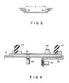
- At least one pair of transmitting and receiving transducers 19 and 20 for calibration are provided on the outer side surface of pig body 12 such that the distance L is left, as a reference, in the axial direction of the pig body.
- An exact pipe inner diameter value can be found by obtaining calibration data from the transmit/receive time of ultrasound and then calibrating measurement values obtained by transmitting/receiving transducers 17 and 18.
- Pig body 12 includes, as set out below, substrates 22 having electronic components for a function circuit, data processing section 23 including a microcomputer, and battery 24 supplying voltage to a respective electronic circuit.
- Moving distance meter 25 for measuring the moving distance of pig body 12 is provided in a recess of the outer periphery of pig body 12 and comprised of arm 25b swingably mounted by pin hinge 25a on the pig body and roller 25d at the free end of arm 25b.
- the number of rotations of roller 25d is counted by rotation meter 25c.
- Arm 25b normally urges roller 25d into abutting engagement with the inner side surface of the pipe line by means of spring 25e which is anchored at its end to a projection of pig body 12.
- Inclination angle meter 26 is provided within the pig body to measure the inclination angle relative to the axis of the pipe line.
- the inclination angle meter is comprised of rotation meter 26a, arm 26b suspended from rotation meter 26a and weight 26c mounted on the forward end of arm 26b.
- Weld spot detector 28 such as an eddy sensor, is mounted on the outer surface of pig body 12 to detect welded spot 27 of pipe line 11.
- Photographing body section 30 is rotatably mounted on the rear end of pig body 12 and rotated by motor 31c through pinion 31b which meshes with rack 31a provided within pig body 12.
- Camera 32 is mounted within photographing body section 30 and film cartridge 33 is contained within the photographing body section 30.
- Camera 32 includes focusing mechanism 37 at the front so that the distance relative to an object to be photographed is measured in an auto-focusing fashion.
- Photographing body section 30 has direct-view photographing window 34 at the front of the camera and side-view photographing window 35 facing the inner side surface of the photographing section.
- Swingable mirror 36 is mounted at the front side of camera 32 so that it can be switched to a direct-view or side-view shot.
- a switching can be made either to the direct-view shot or to the side-view shot by driving motor 60 in accordance with the detection output of eddy sensor 28 or transmitting/receiving transducers 17 and 18 and thus rotating the mirror (36).
- a limit switch is set relative to the front- and side-focusing positions and, in this case, according to the rotation position of photographing body section 30 the limit switch is rotated so that the direct- or side-view shot can be selectively taken.
- Direct-view strobo 38 is provided on the inside of direct-view photographing window 34, and side-view strobo 39 is provided in juxtaposition with side-view photographing window 35.
- Wiper 40 is provided near direct-view photographing window 34 and driven by motor 41 to allow the glass surface of window 34 to be wiped clean.
- Respective driving units within photographing body unit 30 are driven by a power source, such as battery 42.
- the pig device thus explained has a circuit arrangement as shown in Fig. 3.
- Data processing section 53 includes, for example, microcomputer 53a, ROM 53b strong sequence program data, static RAM 53c storing data, such as moving distance, inclination angle, weld shot detection, pipe inner diameter measuring data and processing data, data recorder 53d, and signal generator 53e for generating a timing signal and reference clock.
- Signal generator 53e may be provided outside data processing section 53.
- a plurality of transmitting circuits 45 receives transmission timing signals sequentially sent from data processing section 53 and delivers a high frequency signal to corresponding transmitting transducer 17.
- Transmitting circuit 46 supplies a high frequency signal to transmitting transducer 19.
- the ultrasound from transmitting transducer 17 is, after being echoed backed from the inner surface of the pipe line, received by receiving transducer 18.
- the received signal after being amplified by receiving amplifier circuit 47, is input to multiplier 49.
- Receiving transducer 20 for calibration receives the ultrasound from transmitting transistor 19 for calibration.
- the received ultrasound after being amplified by receiving amplifier circuit 48, is supplied as a signal to multiplexer 49.
- the reception of the signal from receiving amplifier circuits 47, 48 to multiplexer 49 is performed each time multiplexer 49 receives a transmission timing signal from data processing section 53.
- the output of multiplexer 49 is supplied to comparator circuit 50 where it is compared with a reference clock number. It is, therefore, possible to detect the time interval from the transmission to the reception of the ultrasound.
- the outputs of comparator circuit 50 are counted, as the number of pulses, by counter 51.
- the reference clock from data processing section 53 is transmitted to comparator circuit 50 via signal line 52.
- the count output of counter 51 is input to data processing section 53 where it is processed in a softward fashion.
- Moving distance meter 25, inclination angle meter 26 and weld spot detector 28 as shown in Fig. 1 are connected to data processing section 53.
- the processed output of data processing section 53 is delivered as an instruction output so that the shutter, strobo or shot action may be made.
- a pressure difference is created ahead and behind the pipe line with pressure reception sealing cups 14, 15 as a boundary.
- pig body 12 is travelled from a higher to a lower pressure side with the pig body as a reference.
- the moving distance of pig body 12 is detected sequentially by moving distance meter 25 and the corresponding output data is stored in RAM 53c of data processing section 23. After any off-normal or abnormal spot has been detected within the pipe line, a corresponding spot can be located outside the pipe line through the utilization of a record relating to the moving distance.
- transmission timing signals are sequentially generated from data processing section 53 at a predetermined interval of time and supplied to transmitting circuits 45, 46, multiplexer 49 and comparator circuit 50.
- the transmitting circuits (45, 46) delivers a high-frequency signal to the corresponding transmitting transducer (17, 19).
- Transmitting transducer 17 transmits ultrasound 21 onto the inner surface of the pipe line.
- the ultrasound echoed back from the inner surface of pipe line 11 is received by receiving transducer 18.
- the ultrasound of transmitting transducer 19 for calibration is received by receiving transducer 20 which faces the transducer (19) along the axial direction of the pipe line.
- the output of receiving transducer 18 is supplied to multiplexer 49 through receiving amplifier circuit 47 and the output of receiving transducer 20 is input to multiplexer 49 through amplifier circuit 48.
- multiplexer 49 receives outputs from amplifiers 47, 48 and sequentially transmits them to comparator circuit 50.
- Comparator 50 receives a transmission timing signal, and reference block signal via signal line 52, from data processing section 54, so that the time interval from the transmission to the reception of the ultrasound can be known by counting the reference clock signals derived from data processing section 53.
- the count value can be detected by counting the outputs of the comparator circuit by virtue of counter 51.
- the aforementioned count value represents measuring data corresponding to the distance from the outer surface of pig body 12 to the inner side wall of pipe line 11.
- Data processing section 53 receives the count value of counter 51 and, if any calibration data is present, evaluates the pipe inner diameter with the use of the calibration data.
- the inside of the pipe if being in an abnormal or off-normal state, can be known as such from that spot on the pipe liner diameter evaluated. If any off-normal or defect count value is detected, that distance moved by pig body 12 at that time can be known from the output of moving distance meter 25.
- data proceeding section 53 delivers, for example, a shutter drive signal and strobo action control signal, so that the defect state on the inner surface of the pipe can be photographed.
- swingable mirror 36 is set at a position indicated by the dot line in Fig. 1 so that the defect spot on the inner surface of the pipe can be shot with the front lens of camera 32 oriented toward direct-view photographing window 34.
- body section 30 is rotated, while a drive signal is continuously or intermittently supplied to motor 31c, with mirror 36 set at the position indicated by the solid line in Fig.
- data processing section 53 intermittently supplies a shutter drive signal and strobo action control signal to the camera where the spot of interest is photographed.
- the image is recorded on cartridge film 33.
- a spot detection signal is sent to data processing section 53.
- Data processing section 53 upon receipt of a weld spot detection signal, can evaluate that distance, over which pig body 12 has travelled, with the use of an output of moving distance meter 25. In this case, when side-view photographing window 35 of the pig body comes just that position of weld spot 27, a shutter drive signal and strobo action control signal are fed to camera 32 where that weld spot is photographed. As set forth above, any defect on the pipe inner diameter and on the weld spot of the pipe can be photographed with the use of camera 32. Inclination angle data measured by inclination angle meter 26 is input to RAM 53c in data processing section 53, where it is stored.
- That data items thus obtained for example, the inner diameter of the pipe, distance moved by the pig body and inclination angle of the pig relative to the axial direction, etc., are stored in RAM 53c in data processing section 53 and recorded in film cartridge 33. After pig body 12 has been travelled within the pipe line and removed from the pipe line, these data items are input to a proper interface of an external computer. In this way it is possible to evaluate, for example, any defect state within the pipe line and any defect weld spot of the pipe line. If, as the result of such examination, it is found that, for example, the pipe inner surface or weld spot 27 is severely corroded, a corresponding pipe section is replaced by a new one or any other anti-corrosion measure can be taken prompt strictlyly.
- At least one pair of transmitting transducer 17 and receiving transducer 18, as well as a pair of transducers 19, 20 for calibration, are provided in the pig device, thus enabling a plurality of defect spots to be detected during one run of pig body 12 through the pipe line.
- the pig body since the pair of sealing cups 14, 15 for pressure reception are provided, at a predetermined interval, on the side surface of pig body 12, the pig body can properly be run along the axis of the pipe line and, even if any recess is situated in any inner surface portion of the pipe line and even if any air-pressure leakage occurs at one (for example, sealing cup 14) of the pair of sealing cups 14, 15, the pig body can continue to run within the pipe line while, at the same time, receiving an enough great pressure by the other sealing cup.
- These sealing cups 14, 15 are so formed as to have a fish fin-like configuration and has a pliability and, even if the tube inner diameter somewhat varies, the pig body can still be travelled without being interrupted. Where the pipe line is closed at a remote end, the pig body can be moved backward under a back pressure (elevated pressure) and, at that time, the sealing cups can pliably be warped in the back direction.
- pig body 12 has been explained as being continuously run within a pipe line with a pressure difference created ahead and behind sealing cups 14, 15, this invention is not restricted to the aforementioned embodiment. In another embodiment shown in Fig. 4, for example, pig body 12 can be stopped at any proper position within a pipe line.
- Communicating unit 55 is provided on the outer surface of pig body 12 in the longitudinal direction and normally closed by valve unit 56 as indicated by a dotted line in Fig. 4.
- data proceeding section 53 delivers an operation signal to valve unit 56, causing valve unit 56 to be retracted to a position indicated by a solid line in Fig. 4 to open communication unit 55.
- a spot of interest is photographed by camera 32 to obtain a stable, clear image.
- any defect spot on the inner surface of pipe line 11, including any defect weld spot has been explained as been photographed only when it is located at that position, it can continuously been photographed, as a direct- or side-view mode, with the use of a television camera, video tape recorder, and so on, in which case illumination light can be used in place of strobo units 38, 39.
- weld spot detector 28 has been explained as being provided between sealing cups 14 and 15, it may be provided behind sealing cup 15 and, in this case, no particular restriction is made to the type of measurement, shape, etc. Furthermore, a plurality of magnetic members may be provided at predetermined intervals on the outer periphery of the pipe and if, in this case, a magnetic field is detected by a magnetic sensor during the run of pig body 12, any measurement error as induced in conjunction with the travelling distance of pig body 12 can properly been corrected on the pig device of this invention.
Landscapes
- Physics & Mathematics (AREA)
- General Physics & Mathematics (AREA)
- Investigating Or Analyzing Materials By The Use Of Ultrasonic Waves (AREA)
- Length Measuring Devices Characterised By Use Of Acoustic Means (AREA)
Applications Claiming Priority (2)
| Application Number | Priority Date | Filing Date | Title |
|---|---|---|---|
| JP62064239A JP2534698B2 (ja) | 1987-03-20 | 1987-03-20 | 管内検査ピグ装置 |
| JP64239/87 | 1987-03-20 |
Publications (3)
| Publication Number | Publication Date |
|---|---|
| EP0282687A2 true EP0282687A2 (fr) | 1988-09-21 |
| EP0282687A3 EP0282687A3 (en) | 1990-01-03 |
| EP0282687B1 EP0282687B1 (fr) | 1993-09-22 |
Family
ID=13252388
Family Applications (1)
| Application Number | Title | Priority Date | Filing Date |
|---|---|---|---|
| EP88100068A Expired - Lifetime EP0282687B1 (fr) | 1987-03-20 | 1988-01-05 | Furet pour l'examen de points à l'intérieur d'un tube |
Country Status (3)
| Country | Link |
|---|---|
| EP (1) | EP0282687B1 (fr) |
| JP (1) | JP2534698B2 (fr) |
| DE (1) | DE3884242D1 (fr) |
Cited By (13)
| Publication number | Priority date | Publication date | Assignee | Title |
|---|---|---|---|---|
| WO1994018540A1 (fr) * | 1993-02-10 | 1994-08-18 | Kfki Atomenergia Kutató Intézet | Sonde detectrice |
| WO1995003526A1 (fr) * | 1993-07-20 | 1995-02-02 | Commonwealth Scientific And Industrial Research Organisation | Systeme d'inspection d'un conduit |
| EP0623814A3 (fr) * | 1993-05-05 | 1995-08-16 | Rico Mikroelektronik Gmbh | Procédé d'opération d'un dispositif mobile d'inspection d'un canalisation. |
| WO1997046869A1 (fr) * | 1996-05-31 | 1997-12-11 | The University Of Queensland | Detection de defauts dans le verre |
| AT405335B (de) * | 1993-12-30 | 1999-07-26 | Oemv Ag | Vorrichtung und verfahren zur bestimmung von fehlstellen einer rohrleitung für fluide |
| EP0902268A3 (fr) * | 1997-09-13 | 1999-11-17 | Wolfgang Rausch GmbH & Co. Electronic-Maschinenbau | Appareil pour tester la pression |
| AU732132B2 (en) * | 1996-05-31 | 2001-04-12 | University Of Queensland, The | Detection of defects in glass |
| US7159477B2 (en) * | 2002-03-13 | 2007-01-09 | Borealis Technology Oy | Apparatus for inspecting deformation of pipes |
| DE102012002643A1 (de) * | 2012-02-08 | 2013-08-08 | Stefan Raßmann | Autarkes, ortsveränderliches Inline- Messgerät zur Detektion und Aufzeichnung von Leckagen in Gas- und Flüssiggaspipelines. |
| US20130276828A1 (en) * | 2012-04-20 | 2013-10-24 | Cokebusters Ltd. | Relateing to pipeline pigs |
| CN106595562A (zh) * | 2016-12-07 | 2017-04-26 | 武汉长盛工程检测技术开发有限公司 | 引水隧道质量在线成像快速检测装置及方法 |
| CN108106578A (zh) * | 2018-01-19 | 2018-06-01 | 沈阳仪表科学研究院有限公司 | 超声测径测壁厚管道内检测器 |
| CN110220972A (zh) * | 2019-05-25 | 2019-09-10 | 中海油能源发展股份有限公司 | 一种长输管道压电超声波探伤内检测器 |
Families Citing this family (6)
| Publication number | Priority date | Publication date | Assignee | Title |
|---|---|---|---|---|
| US5285689A (en) * | 1991-07-16 | 1994-02-15 | The United States Of America As Represented By The United States Department Of Energy | Piping inspection instrument carriage with precise and repeatable position control and location determination |
| US5392527A (en) * | 1993-07-12 | 1995-02-28 | Wheelabrator Engineered Systems, Inc. | Annulus measuring device |
| US5587534A (en) * | 1994-10-28 | 1996-12-24 | The United States Of America As Represented By The Secretary Of Commerce | Wall thickness and flow detection apparatus and method for gas pipelines |
| JP4146077B2 (ja) * | 2000-12-26 | 2008-09-03 | 東京瓦斯株式会社 | 管内走行装置の計測切替方法 |
| DE102007011445B4 (de) * | 2007-03-06 | 2012-11-08 | Hochschule Wismar University Of Technology, Business And Design | Verfahren und Vorrichtung zur Untersuchung eines geschweißten Hohlprofilträgers |
| CN114061500A (zh) * | 2021-11-10 | 2022-02-18 | 昆明理工大学 | 一种基于声发射技术的管道变形失稳动态监测系统 |
Family Cites Families (8)
| Publication number | Priority date | Publication date | Assignee | Title |
|---|---|---|---|---|
| FR2122661A5 (fr) * | 1971-01-19 | 1972-09-01 | Elf Union | |
| US3885091A (en) * | 1973-10-24 | 1975-05-20 | Halliburton Co | Method and apparatus for pipeline inspection |
| JPS56117359A (en) * | 1980-02-20 | 1981-09-14 | Tanashin Denki Co | Cassette type tape recorder |
| JPS5753658A (en) * | 1980-09-18 | 1982-03-30 | Toshiba Corp | Nondestructive inspection device |
| GB2097537B (en) * | 1981-04-27 | 1985-10-02 | British Gas Corp | A pipeline inspectioon vehicle |
| JPS5938187U (ja) * | 1982-09-03 | 1984-03-10 | 株式会社クボタ | 管内面検査装置の走行装置 |
| NO851590L (no) * | 1984-05-14 | 1985-11-15 | Kraftwerk Union Ag | Selvdrevet inspeksjons- og tilsynskjoeretoey. |
| DE3419683A1 (de) * | 1984-05-24 | 1985-11-28 | Mannesmann AG, 4000 Düsseldorf | Rohrmolch mit fahrwerken |
-
1987
- 1987-03-20 JP JP62064239A patent/JP2534698B2/ja not_active Expired - Fee Related
-
1988
- 1988-01-05 DE DE88100068T patent/DE3884242D1/de not_active Expired - Lifetime
- 1988-01-05 EP EP88100068A patent/EP0282687B1/fr not_active Expired - Lifetime
Cited By (18)
| Publication number | Priority date | Publication date | Assignee | Title |
|---|---|---|---|---|
| WO1994018540A1 (fr) * | 1993-02-10 | 1994-08-18 | Kfki Atomenergia Kutató Intézet | Sonde detectrice |
| EP0623814A3 (fr) * | 1993-05-05 | 1995-08-16 | Rico Mikroelektronik Gmbh | Procédé d'opération d'un dispositif mobile d'inspection d'un canalisation. |
| WO1995003526A1 (fr) * | 1993-07-20 | 1995-02-02 | Commonwealth Scientific And Industrial Research Organisation | Systeme d'inspection d'un conduit |
| AT405335B (de) * | 1993-12-30 | 1999-07-26 | Oemv Ag | Vorrichtung und verfahren zur bestimmung von fehlstellen einer rohrleitung für fluide |
| WO1997046869A1 (fr) * | 1996-05-31 | 1997-12-11 | The University Of Queensland | Detection de defauts dans le verre |
| AU732132B2 (en) * | 1996-05-31 | 2001-04-12 | University Of Queensland, The | Detection of defects in glass |
| US6236734B1 (en) | 1996-05-31 | 2001-05-22 | The University Of Queensland | Detection of defects in glass |
| EP0902268A3 (fr) * | 1997-09-13 | 1999-11-17 | Wolfgang Rausch GmbH & Co. Electronic-Maschinenbau | Appareil pour tester la pression |
| US7159477B2 (en) * | 2002-03-13 | 2007-01-09 | Borealis Technology Oy | Apparatus for inspecting deformation of pipes |
| DE102012002643A1 (de) * | 2012-02-08 | 2013-08-08 | Stefan Raßmann | Autarkes, ortsveränderliches Inline- Messgerät zur Detektion und Aufzeichnung von Leckagen in Gas- und Flüssiggaspipelines. |
| US20130276828A1 (en) * | 2012-04-20 | 2013-10-24 | Cokebusters Ltd. | Relateing to pipeline pigs |
| US8894772B2 (en) * | 2012-04-20 | 2014-11-25 | Cokebuster Ltd. | Relateing to pipeline pigs |
| GB2501312B (en) * | 2012-04-20 | 2017-04-26 | Cokebusters Ltd | Improvements in or relating to pipeline pigs |
| CN106595562A (zh) * | 2016-12-07 | 2017-04-26 | 武汉长盛工程检测技术开发有限公司 | 引水隧道质量在线成像快速检测装置及方法 |
| CN106595562B (zh) * | 2016-12-07 | 2019-01-15 | 武汉长盛工程检测技术开发有限公司 | 引水隧道质量在线成像快速检测装置及方法 |
| CN108106578A (zh) * | 2018-01-19 | 2018-06-01 | 沈阳仪表科学研究院有限公司 | 超声测径测壁厚管道内检测器 |
| CN108106578B (zh) * | 2018-01-19 | 2024-02-27 | 沈阳仪表科学研究院有限公司 | 超声测径测壁厚管道内检测器 |
| CN110220972A (zh) * | 2019-05-25 | 2019-09-10 | 中海油能源发展股份有限公司 | 一种长输管道压电超声波探伤内检测器 |
Also Published As
| Publication number | Publication date |
|---|---|
| EP0282687A3 (en) | 1990-01-03 |
| EP0282687B1 (fr) | 1993-09-22 |
| JP2534698B2 (ja) | 1996-09-18 |
| DE3884242D1 (de) | 1993-10-28 |
| JPS63231260A (ja) | 1988-09-27 |
Similar Documents
| Publication | Publication Date | Title |
|---|---|---|
| EP0282687A2 (fr) | Furet pour l'examen de points à l'intérieur d'un tube | |
| EP0607611B1 (fr) | Système robot pour conduite - conduite, et procédé de mesure de la position dudit robot et de communication avec ledit robot. | |
| EP0771241B1 (fr) | Procede automatise de verification des soudures bout a bout et de diagnostic des defauts | |
| EP0051912B1 (fr) | Dispositif pour la mesure de la géométrie intérieure des tuyaux | |
| JPS6450903A (en) | Measuring apparatus of shape of inside of tube | |
| CA1206278A (fr) | Controle au fluoroscope des soudures peripheriques de canalisations | |
| JPH0312689B2 (fr) | ||
| EP1172155A2 (fr) | Racleur de conduite | |
| CA1174094A (fr) | Dispositif photographique a mecanisme essuyeur de l'orifice d'observation pour le controle interne des pipelines | |
| EP2239564B1 (fr) | Procede d'inspection de soudage et appareil d'inspection de soudage | |
| CA1189944A (fr) | Dispositif de diagraphie | |
| JP3816763B2 (ja) | 管内検査装置及び管内検査方法 | |
| JPH06288734A (ja) | 立体物検査装置 | |
| JP3012118B2 (ja) | 管内ロボット位置計測方法 | |
| JP3816764B2 (ja) | 管内検査装置及び管内検査方法 | |
| JP3596125B2 (ja) | 炉内溶融物の液面レベル測定方法およびその装置 | |
| JPH08304293A (ja) | 管内走行ロボット | |
| JPS63256851A (ja) | 超音波探傷装置 | |
| JP2003004434A (ja) | 管内検査方法 | |
| JPS60205254A (ja) | 管の超音波探傷方法 | |
| JPH0475486B2 (fr) | ||
| JP2001136592A (ja) | 超音波送受波装置 | |
| JP2001165867A (ja) | 表面検査装置 | |
| JPS6357116A (ja) | 鋼材切断装置 | |
| JP3843642B2 (ja) | 金属板のエッジ検出方法 |
Legal Events
| Date | Code | Title | Description |
|---|---|---|---|
| PUAI | Public reference made under article 153(3) epc to a published international application that has entered the european phase |
Free format text: ORIGINAL CODE: 0009012 |
|
| 17P | Request for examination filed |
Effective date: 19880105 |
|
| AK | Designated contracting states |
Kind code of ref document: A2 Designated state(s): DE FR GB NL |
|
| PUAL | Search report despatched |
Free format text: ORIGINAL CODE: 0009013 |
|
| AK | Designated contracting states |
Kind code of ref document: A3 Designated state(s): DE FR GB NL |
|
| RHK1 | Main classification (correction) |
Ipc: G01M 3/00 |
|
| 17Q | First examination report despatched |
Effective date: 19910502 |
|
| GRAA | (expected) grant |
Free format text: ORIGINAL CODE: 0009210 |
|
| AK | Designated contracting states |
Kind code of ref document: B1 Designated state(s): DE FR GB NL |
|
| PG25 | Lapsed in a contracting state [announced via postgrant information from national office to epo] |
Ref country code: NL Effective date: 19930922 Ref country code: FR Effective date: 19930922 Ref country code: DE Effective date: 19930922 |
|
| REF | Corresponds to: |
Ref document number: 3884242 Country of ref document: DE Date of ref document: 19931028 |
|
| PG25 | Lapsed in a contracting state [announced via postgrant information from national office to epo] |
Ref country code: GB Effective date: 19940105 |
|
| EN | Fr: translation not filed | ||
| NLV1 | Nl: lapsed or annulled due to failure to fulfill the requirements of art. 29p and 29m of the patents act | ||
| PLBE | No opposition filed within time limit |
Free format text: ORIGINAL CODE: 0009261 |
|
| STAA | Information on the status of an ep patent application or granted ep patent |
Free format text: STATUS: NO OPPOSITION FILED WITHIN TIME LIMIT |
|
| GBPC | Gb: european patent ceased through non-payment of renewal fee |
Effective date: 19940105 |
|
| 26N | No opposition filed |