EP0282748A1 - Vorrichtung zur dosierbaren Klebstoff-Applikation - Google Patents
Vorrichtung zur dosierbaren Klebstoff-Applikation Download PDFInfo
- Publication number
- EP0282748A1 EP0282748A1 EP88102311A EP88102311A EP0282748A1 EP 0282748 A1 EP0282748 A1 EP 0282748A1 EP 88102311 A EP88102311 A EP 88102311A EP 88102311 A EP88102311 A EP 88102311A EP 0282748 A1 EP0282748 A1 EP 0282748A1
- Authority
- EP
- European Patent Office
- Prior art keywords
- adhesive
- cooling
- temperature
- chamber
- metering
- Prior art date
- Legal status (The legal status is an assumption and is not a legal conclusion. Google has not performed a legal analysis and makes no representation as to the accuracy of the status listed.)
- Granted
Links
- 239000000853 adhesive Substances 0.000 title claims abstract description 58
- 230000001070 adhesive effect Effects 0.000 title claims abstract description 58
- 238000010438 heat treatment Methods 0.000 claims abstract description 29
- 238000001816 cooling Methods 0.000 claims abstract description 24
- 239000000758 substrate Substances 0.000 claims abstract description 3
- 125000006850 spacer group Chemical group 0.000 claims description 7
- 239000002826 coolant Substances 0.000 claims description 5
- 239000002184 metal Substances 0.000 claims description 3
- 230000000087 stabilizing effect Effects 0.000 claims description 2
- 239000003795 chemical substances by application Substances 0.000 abstract 1
- 239000004020 conductor Substances 0.000 abstract 1
- 238000000742 single-metal deposition Methods 0.000 abstract 1
- 238000005476 soldering Methods 0.000 description 4
- 230000006641 stabilisation Effects 0.000 description 4
- 238000011105 stabilization Methods 0.000 description 4
- 230000006835 compression Effects 0.000 description 2
- 238000007906 compression Methods 0.000 description 2
- 230000002349 favourable effect Effects 0.000 description 2
- 238000012545 processing Methods 0.000 description 2
- 230000035939 shock Effects 0.000 description 2
- 238000010521 absorption reaction Methods 0.000 description 1
- 230000033228 biological regulation Effects 0.000 description 1
- 230000001419 dependent effect Effects 0.000 description 1
- 238000011161 development Methods 0.000 description 1
- 230000000694 effects Effects 0.000 description 1
- 238000009413 insulation Methods 0.000 description 1
- 238000012423 maintenance Methods 0.000 description 1
- 239000000463 material Substances 0.000 description 1
- 238000005259 measurement Methods 0.000 description 1
- 230000005855 radiation Effects 0.000 description 1
- 239000004065 semiconductor Substances 0.000 description 1
- 238000012546 transfer Methods 0.000 description 1
- 239000012808 vapor phase Substances 0.000 description 1
Images
Classifications
-
- H—ELECTRICITY
- H05—ELECTRIC TECHNIQUES NOT OTHERWISE PROVIDED FOR
- H05K—PRINTED CIRCUITS; CASINGS OR CONSTRUCTIONAL DETAILS OF ELECTRIC APPARATUS; MANUFACTURE OF ASSEMBLAGES OF ELECTRICAL COMPONENTS
- H05K13/00—Apparatus or processes specially adapted for manufacturing or adjusting assemblages of electric components
- H05K13/04—Mounting of components, e.g. of leadless components
- H05K13/046—Surface mounting
- H05K13/0469—Surface mounting by applying a glue or viscous material
-
- B—PERFORMING OPERATIONS; TRANSPORTING
- B05—SPRAYING OR ATOMISING IN GENERAL; APPLYING FLUENT MATERIALS TO SURFACES, IN GENERAL
- B05C—APPARATUS FOR APPLYING FLUENT MATERIALS TO SURFACES, IN GENERAL
- B05C11/00—Component parts, details or accessories not specifically provided for in groups B05C1/00 - B05C9/00
- B05C11/10—Storage, supply or control of liquid or other fluent material; Recovery of excess liquid or other fluent material
-
- B—PERFORMING OPERATIONS; TRANSPORTING
- B05—SPRAYING OR ATOMISING IN GENERAL; APPLYING FLUENT MATERIALS TO SURFACES, IN GENERAL
- B05C—APPARATUS FOR APPLYING FLUENT MATERIALS TO SURFACES, IN GENERAL
- B05C5/00—Apparatus in which liquid or other fluent material is projected, poured or allowed to flow on to the surface of the work
- B05C5/001—Apparatus in which liquid or other fluent material is projected, poured or allowed to flow on to the surface of the work incorporating means for heating or cooling the liquid or other fluent material
-
- B—PERFORMING OPERATIONS; TRANSPORTING
- B05—SPRAYING OR ATOMISING IN GENERAL; APPLYING FLUENT MATERIALS TO SURFACES, IN GENERAL
- B05C—APPARATUS FOR APPLYING FLUENT MATERIALS TO SURFACES, IN GENERAL
- B05C5/00—Apparatus in which liquid or other fluent material is projected, poured or allowed to flow on to the surface of the work
- B05C5/02—Apparatus in which liquid or other fluent material is projected, poured or allowed to flow on to the surface of the work the liquid or other fluent material being discharged through an outlet orifice by pressure, e.g. from an outlet device in contact or almost in contact, with the work
-
- B—PERFORMING OPERATIONS; TRANSPORTING
- B05—SPRAYING OR ATOMISING IN GENERAL; APPLYING FLUENT MATERIALS TO SURFACES, IN GENERAL
- B05C—APPARATUS FOR APPLYING FLUENT MATERIALS TO SURFACES, IN GENERAL
- B05C9/00—Apparatus or plant for applying liquid or other fluent material to surfaces by means not covered by any preceding group, or in which the means of applying the liquid or other fluent material is not important
- B05C9/08—Apparatus or plant for applying liquid or other fluent material to surfaces by means not covered by any preceding group, or in which the means of applying the liquid or other fluent material is not important for applying liquid or other fluent material and performing an auxiliary operation
- B05C9/14—Apparatus or plant for applying liquid or other fluent material to surfaces by means not covered by any preceding group, or in which the means of applying the liquid or other fluent material is not important for applying liquid or other fluent material and performing an auxiliary operation the auxiliary operation involving heating or cooling
Definitions
- the invention relates to a device for metering adhesive application to a substrate, in particular for SMD placement machines, in which the adhesive can be fed to a metering needle under the action of pressure.
- adhesive droplets are applied by means disposed in a positioning metering device initially, on which the SMD components are then fitted.
- the adhesive then hardens through exposure to temperature or UV radiation.
- the SMD components are then fixed in the correct position so firmly on the circuit board that the electrical connection can be made in the wave pool, by reflow soldering or by soldering in the vapor phase.
- the metering devices used for the adhesive application essentially consist of an adhesive cartridge which is arranged in a resilient holder and can be pressurized with compressed air, a metering needle inserted into the adhesive cartridge and a spacer assigned to the metering needle.
- this metering device arranged in the positioning unit of the SMD automatic placement machine is lowered until the spacer sits on the printed circuit board, the shock caused thereby being absorbed by the adhesive cartridge being deflected.
- an adhesive drop is then pressed onto the circuit board by pressurizing the adhesive cartridge with compressed air, the amount of adhesive metered in dependent on the metering time and the pressure applied to the adhesive cartridge depends on the needle geometry and the viscosity of the adhesive. The dynamic viscosity in turn depends on the temperature of the adhesive.
- the invention has for its object to increase the metering accuracy in a generic device for metering adhesive application.
- the metering needle is assigned a cooling and / or heating device for stabilizing the temperature of the adhesive passed therethrough.
- the invention is based on the finding that temperature fluctuations have a very large influence on the behavior of the adhesive during metering.
- Heating or cooling e.g. Changing the ambient temperature or increasing the adhesive temperature due to the air compression in the cartridge cause significant changes in the viscosity of the adhesive.
- Measurements on commercially available adhesives for SMD technology have shown that a temperature increase of 5 ° C doubles the volume of the applied adhesive drops.
- the effort to stabilize the temperature of the adhesive in the cartridge would be much too great, since this would require an effective cooling and / or heating output of approximately 7 watts.
- the low flow rates result in an extremely favorable ratio of the adhesive volume flow to the surface.
- the cooling and / or heating device comprises a chamber which at least in regions surrounds the metering needle and to which a cooling and / or heating medium can be supplied.
- a cooling and / or heating medium can be supplied.
- a tube for the supply of the coolant and / or heating medium then opens into the lower region of the chamber, the countercurrent principle, which is favorable for the temperature stabilization of the adhesive, can be implemented in a particularly simple manner.
- a temperature sensor can then be attached to the tube, which is preferably made of metal with regard to thermal conductivity, and which enables precise regulation and maintenance of the temperature of the adhesive passed through the metering needle.
- the tube enables the detachable connection of a hose for the supply of the coolant and / or heating medium. There is also good thermal contact with the dispensing needle.
- the cooling and / or heating device comprises a Peltier element.
- a thermocouple built with semiconductor materials can then be used both for thermoelectric cooling and for thermoelectric heating.
- the absorption or development of the so-called Peltier heat which can be controlled by simply reversing the current direction, then enables extremely flexible temperature stabilization at a temperature level below, above or at room temperature.
- cooling and / or heating medium can be passed through a heat exchanger connected to the Peltier element before entering the chamber.
- the Peltier element is assigned a second heat exchanger for the delivery or supply of heat to or from the environment.
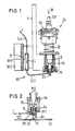
- the drawing shows a highly simplified schematic representation of a dosing device Dv for applying adhesive drops KT to a printed circuit board Lp. Then SMD modules are then applied to this circuit board Lp and fixed until the soldering by the adhesive drops KT.
- the entire dosing device Dv is used in a program-controlled SMD placement machine, which is designed for simultaneous processing of positions with the same position. In this way, adhesive drops KT for a specific SMD module can then be applied to a printed circuit board Lp, while simultaneously the corresponding SMD module is placed on another printed circuit board Lp already provided with adhesive drops KT.
- the entire dosing device Dv is arranged via a holder H in a positioning unit of the SMD placement machine, which is not shown in detail.
- an adhesive cartridge KK filled with highly viscous adhesive, the lower end of which carries a metering needle Dn designed as a hollow needle.
- the KK adhesive cartridge used as a disposable cartridge can be easily replaced by loosening a resilient clamping bracket Kb.
- a flexible hose Sc1 opens into the dosing device Dv from above, through which compressed air D1 can be applied to the adhesive cartridge KK.
- the entire metering device Dv is lowered by the positioning unit until one is labeled Ah Neter spacer sits on the circuit board Lp, the shock caused thereby is absorbed by deflecting the metering device Dv by means of a compression spring Df.
- the adhesive droplet Kt is then pressed onto the circuit board Lp by applying compressed air Dl to the adhesive cartridge KK, the metered amount of adhesive depending on the dosing time and the pressure of the Compressed air Dl depends on the length and the clear cross section of the dispensing needle Dn and in particular also on the viscosity of the adhesive.
- a cooling and / or heating device designated overall by KH, with which the temperature of the adhesive passed through the dosing needle Dn can be stabilized.
- the cooling and / or heating device KH comprises a Peltier element PE which is connected on one side to a first heat exchanger Wt1 and on the other side to a second heat exchanger Wt2 and is fastened to the holder H of the metering device Dv.
- Air L with a pressure of, for example, 0.5 bar is supplied to the first heat exchanger Wt1 via a flexible hose Sc2 as a cooling and / or heating medium.
- the Peltier element PE when the air L flows through the first heat exchanger Wt1, it is cooled or warmed via a further flexible hose Sc3 and a tube R into a dosing needle Dn to its end area chamber Ka introduced at a distance.
- a temperature sensor TM On the metal tube R is a temperature sensor TM, such as a thermocouple attached by soldering.
- the temperature sensor TM is connected to a PID controller, not shown, which controls the current and the current direction of the Peltier element PE to stabilize the temperature of the adhesive passed through the metering needle Dn.
- the chamber Ka mentioned above is formed by the upper hollow cylindrical or cup-shaped part of the spacer Ah and formed by a hollow cylinder Hz made of plastic for better heat insulation.
- the tempered air L entering the chamber Ka through the tube R is swirled in the chamber Ka and then discharged upward through an annular gap Rs of the hollow cylinder Hz as exhaust air into the room.
- the swirling of the air L to improve the heat transfer to the metering needle Dn is shown in FIG. 2 by a helical arrow Pf1, while the exit of the air L from the chamber Ka is shown by arrows Pf2.
- the hollow cylinder Hz is fastened in the holder H via a bushing B and an annular retaining screw Hs in such a way that the adhesive cartridge KK and the metering needle Dn can be easily replaced.
- the temperature of the adhesive passed through the metering needle Dn can be stabilized to a desired temperature level, so that the metering accuracy is considerably improved by the constant viscosity of the emerging adhesive.
- the stabilization takes place in particular at the room temperature level, since the viscosity of commercially available SMD adhesives desired for processing is generally adjusted to room temperature.
- a heating of the adhesive caused by the application of compressed air D1 is then compensated for by the cooling effect of the Peltier element PE.
- the Peltier element PE can also be used as a heating device.
- the adhesive can be dosed onto the printed circuit board Lp at a temperature of 40 ° C at a lower viscosity, while then the SMD components adhere very well to the printed circuit board Lp at room temperature due to the correspondingly higher viscosity of the adhesive.
- the adhesive can also be metered at a temperature below room temperature, in which case the Peltier element PE then acts as a pure cooling device.
Landscapes
- Engineering & Computer Science (AREA)
- Manufacturing & Machinery (AREA)
- Microelectronics & Electronic Packaging (AREA)
- Application Of Or Painting With Fluid Materials (AREA)
- Coating Apparatus (AREA)
Abstract
Description
- Die Erfindung betrifft eine Vorrichtung zur dosierbaren Klebstoff-Applikation auf ein Substrat, insbesondere für SMD-Bestückautomaten, bei welcher der Klebstoff unter Einwirkung von Druck einer Dosiernadel zuführbar ist.
- Bei der automatischen Bestückung von Leiterplatten mit SMD-Bausteinen für die Oberflächen-Montage (SMD = Surface Mounted Devices) werden durch eine in einer Positioniereinheit angeordnete Dosiervorrichtung zunächst Klebstoff-Tropfen aufgebracht, auf welche die SMD-Bausteine dann aufgesetzt werden. Der Klebstoff härtet dann durch die Einwirkung von Temperatur oder UV-Strahlung aus. Die SMD-Bausteine sind danach in der richtigen Lage so fest auf der Leiterplatte fixiert, daß die elektrische Verbindung im Schwallbad, durch Reflow-Löten oder durch Löten in der Dampf-Phase hergestellt werden kann. Die für die Klebstoff-Applikation eingesetzten Dosiervorrichtungen bestehen im wesentlichen aus einer in einer federnden Halterung angeordneten und mit Druckluft beaufschlagbaren Klebstoff-Kartusche, einer in die Klebstoff-Kartusche eingesetzten Dosiernadel und einem der Dosiernadel zugeordneten Anbstandshalter. Zum Aufbringen eines Klebstoff-Tropfens wird diese in der Positioniereinheit des SMD-Bestückautomaten angeordnete Dosiervorrichtung abgesenkt, bis der Abstandshalter auf der Leiterplatte aufsitzt, wobei der dadurch verursachte Stoß durch ein Einfedern der Klebstoff-Kartusche aufgefangen wird. Aus der sich in dieser abgesenkten Stellung knapp oberhalb der Leiterplatte befindlichen Dosiernadel wird dann durch Druckluftbeaufschlagung der Klebstoff-Kartusche ein Klebstoff-Tropfen auf die Leiterplatte gepreßt, wobei die aufdosierte Klebstoffmenge von der Dosierzeit, vom Druck mit dem die Klebstoff-Kartusche beaufschlagt wird, von der Nadelgeometrie und der Viskosität des Klebstoffes abhängt. Die dynamische Viskosität hängt ihrerseits von der Temperatur des Klebstoffes ab.
- Der Erfindung liegt die Aufgabe zugrunde, bei einer gattungsgemäßen Vorrichtung zur dosierbaren Klebstoff-Applikation die Dosiergenauigkeit zu erhöhen.
- Diese Aufgabe wird erfindungsgemäß dadurch gelöst, daß der Dosiernadel eine Kühl- und/oder Heizeinrichtung zur Temperaturstabilisierung des hindurchgeführten Klebstoffes zugeordnet ist.
- Der Erfindung liegt die Erkenntnis zugrunde, daß Temperaturschwankungen einen sehr großen Einfluß auf das Verhalten des Klebstoffes beim Dosieren ausüben. Erwärmung oder Abkühlung, z.B. Änderung der Umgebungstemperatur oder Erhöhung der Klebstofftemperatur durch die Luftkompression in der Kartusche bewirken erhebliche Viskositätsänderungen des Klebstoffes. Messungen an handelsüblichen Klebstoffen für die SMD-Technik haben ergeben, daß eine Temperaturerhöhung um 5° C eine Verdoppelung der Volumina der applizierten Klebstoff-Tropfen bewirkt. Andererseits wäre der Aufwand für eine Temperaturstabilisierung des Klebstoffes in der Kartusche viel zu groß, da hierzu eine effektive Kühl- und/oder Heizleistung von ca. 7 Watt benötigt würde. Wesentlich einfacher kann jedoch eine Temperaturstabilisierung des durch die Dosiernadel hindurchgeführten Klebstoffes mit einer Kühl- und/oder Heizeinrichtung geringer Leistung bewirkt werden. Insbesondere ergibt sich bei einer Temperaturbeeinflussung im Bereich der Dosiernadel aufgrund der geringen Durchflußgeschwindigkeiten ein äußerst günstiges Verhältnis des Klebstoffvolumenstroms zur Oberfläche.
- Gemäß einer bevorzugten Ausgestaltung der Erfindung umfaßt die Kühl- und/oder Heizeinrichtung eine die Dosiernadel zumindest bereichsweise umgebende Kammer, welcher ein Kühl- und/oder Heizmittel zuführbar ist. Durch eine derartige indirekte Kühlung und/oder Heizung mit einem vorzugsweisen gasförmigen Kühl- und/oder Heizmittel kann im Hinblick auf den Platzmangel im Bereich der Dosiernadel eine besonders effektive Temperaturstabilisierung erzielt werden.
- Mündet dann in den unteren Bereich der Kammer ein Röhrchen für die Zufuhr des Kühl- und/oder Heizmittels ein, so kann auf besonders einfache Weise das für die Temperaturstabilisierung des Klebstoffes günstige Gegenstromprinzip realisiert werden. Außerdem kann dann an das im Hinblick auf die Wärmeleitfähigkeit vorzugsweise aus Metall bestehende Röhrchen ein Temperatur-Meßfühler angebracht werden, der eine genaue Regelung und Konstanthaltung der Temperatur des durch die Dosiernadel hindurchgeführten Klebstoffes ermöglicht. Das Röhrchen ermöglicht den lösbaren Anschuß eines Schlauches für die Zufuhr des Kühl- und/oder Heizmittels. Außerdem ergibt sich ein guter Wärmekontakt zur Dosiernadel.
- Es hat sich auch als vorteilhaft erwiesen, wenn an der Kammer ein nach unten ragender Abstandshalter angebracht ist. Durch eine derartige Integration des Abstandshalters ergibt sich eine weitere Verringerung des baulichen Aufwands.
- Gemäß einer besonders bevorzugten Ausgestaltung der Erfindung umfaßt die Kühl- und/oder Heizeinrichtung ein Peltier-Element. Ein derartiges mit Halbleitermaterialien gebautes Thermoelement kann dann sowohl zur thermoelektrischen Kühlung als auch zur thermoelektrischen Heizung verwendet werden. Die Absorption oder Entwicklung der sogenannten Peltierwärme, die durch eine einfache Umkehr der Stromrichtung gesteuert werden kann, ermöglicht dann eine äußerst flexible Temperaturstabilisierung auf einem unter, über oder bei Raumtemperatur liegenden Temperaturniveau.
- Ein besonders geringer Aufwand bei effektiver Kühlung oder Heizung ergibt sich dann, wenn das Kühl- und/oder Heizmittel vor dem Eintritt in die Kammer durch einen mit dem Peltier-Element verbundenen Wärmetauscher hindurchführbar ist. In diesem Fall ist es dann auch zweckmäßig, wenn dem Peltier-Element ein zweiter Wärmetauscher für die Abgabe oder Zufuhr von Wärme an oder aus der Umgebung zugeordnet ist.
- Im folgenden wird ein Ausführungsbeispiel der Erfindung anhand der Zeichnung näher erläutert.
- Es zeigen
- Fig. 1 einen teilweisen Längsschnitt durch eine Dosiervorrichtung für das berührungslose Aufbringen von Klebstoff-Tropfen auf eine Leiterplatte und
- Fig. 2 den temperaturstabilisierten Dosiernadelbereich der Dosiervorrichtung gemäß Fig. 1 im Detail.
- Die Zeichnung zeigt in stark vereinfachter schematischer Darstellung eine Dosiervorrichtung Dv zum Aufbringen von Klebstoff-Tropfen KT auf eine Leiterplatte Lp. Auf diese Leiterplatte Lp werden dann anschließend SMD-Bausteine aufgebracht und bis zum Löten durch die Klebstoff-Tropfen KT fixiert. Die gesamte Dosiervorrichtung Dv wird hierbei in einem programmgesteuerten SMD-Bestückautomaten eingesetzt, welcher für die Simultanbearbeitung positionsgleicher Arbeitsgänge ausgelegt ist. Auf diese Weise können dann auf eine Leiterplatte Lp Klebstoff-Tropfen KT für einen bestimmten SMD-Baustein aufgebracht werden, während simultan dazu auf eine andere, bereits mit Klebstoff-Tropfen KT versehene Leiterplatte Lp der entsprechende SMD-Baustein aufgesetzt wird.
- Die gesamte Dosiervorrichtung Dv ist über eine Halterung H in einer nicht näher dargestellten Positioniereinheit des SMD-Bestückautomaten angeordnet. In der Dosiervorrichtung Dv ist eine mit hochviskosem Klebstoff gefüllte Klebstoff-Kartusche KK angeordnet, deren unteres Ende eine als Hohlnadel ausgebildete Dosiernadel Dn trägt. Die als Einweg-Kartusche eingesetzte Klebstoff-Kartusche KK kann durch das Lösen eines federnden Klemmbügels Kb leicht ausgewechselt werden. Von oben her mündet in die Dosiervorrichtung Dv ein flexibler Schlauch Sc1 ein, über welchen die Klebstoff-Kartusche KK mit Druckluft D1 beaufschlagt werden kann. Zum Aufbringen der Klebstoff-Tropfen KT auf die Leiterplatte Lp wird die gesamte Dosiervorrichtung Dv durch die Positoniereinheit abgesenkt, bis ein mit Ah bezeich neter Abstandshalter auf der Leiterplatte Lp aufsitzt, wobei der dadurch verursachte Stoß durch Einfedern der Dosiervorrichtung Dv mittels einer Druckfeder Df aufgefangen wird. Aus der sich in dieser abgesenkten Stellung knapp oberhalb der Leiterplatte Lp befindlichen Dosiernadel Dn wird dann durch die Beaufschlagung der Klebstoff-Kartusche KK mit Druckluft Dl der Kleber-Tropfen Kt auf die Leiterplatte Lp gepreßt, wobei die aufdosierte Klebstoffmenge von der Dosierzeit, vom Druck der Druckluft Dl, von der Länge und dem lichten Querschnitt der Dosiernadel Dn und insbesondere auch von der Viskosität des Klebstoffes abhängt.
- Um nun die Dosiergenauigkeit zu steigern, ist eine insgesamt mit KH bezeichnete Kühl- und/oder Heizeinrichtung vorgesehen, mit welcher die Temperatur des durch die Dosiernadel Dn hindurchgeführten Klebstoffes stabilisiert werden kann. Die Kühl- und/oder Heizeinrichtung KH umfaßt ein Peltier-Element PE, welches auf seiner einen Seite mit einem ersten Wärmetauscher Wt1 und auf seiner anderen Seite mit einem zweiten Wärmetauscher Wt2 verbunden und an der Halterung H der Dosiervorrichtung Dv befestigt ist. Dem ersten Wärmetauscher Wt1 wird über einen flexiblen Schlauch Sc2 als Kühl- und/oder Heizmittel Luft L mit einem Druck von beispielsweise 0,5 bar zugeführt. Die je nach den Erfordernissen vom Peltier-Element PE und dem mit Rippen versehenen zweiten Wärmetauscher Wt2 beim Durchströmen des ersten Wärmetauschers Wt1 gekühlte oder erwärmte Luft L wird dann über einen weiteren flexiblen Schlauch Sc3 und ein Röhrchen R in eine die Dosiernadel Dn bis auf deren Endbereich mit Abstand umgebende Kammer Ka eingeleitet. An dem aus Metall bestehenden Röhrchen R ist ein Temperatur-Meßfühler TM, wie z.B. ein Termoelement durch Löten befestigt. Der Temperatur-Meßfühler TM ist mit einem nicht näher dargestellten PID-Regler verbunden, welcher den Strom und die Stromrichtung des Peltier-Elements PE zur Temperaturstabilisierung des durch die Dosiernadel Dn hindurchgeführten Klebstoffes steuert.
- Die vorstehende erwähnte Kammer Ka wird durch den oberen hohlzylindrischen bzw. becherförmigen Teils des Abstandshalters Ah und durch einen zur besseren Wärmeisolation aus Kunststoff bestehenden Hohlzylinder Hz gebildet. Die durch das Röhrchen R in die Kammer Ka eintretende temperierte Luft L wird in der Kammer Ka verwirbelt und dann nach oben durch einen Ringspalt Rs des Hohlzylinders Hz als Abluft in den Raum abgegeben. Die zur Verbesserung des Wärmeübergangs zur Dosiernadel Dn erwünschte Verwirbelung der Luft L ist in Fig. 2 durch einen wendelförmigen Pfeil Pf1 aufgezeigt, während der Austritt der Luft L aus der Kammer Ka durch Pfeile Pf2 aufgezeigt ist. Die Befestigung des Hohlzylinders Hz in der Halterung H erfolgt über eine Buchse B und eine ringförmige Halteschraube Hs derart, daß die Klebstoff-Kartusche KK und die Dosiernadel Dn leicht ausgetauscht werden können.
- Mit Hilfe der vorstehend beschriebenen Kühl- und/oder Heizeinrichtung KH kann die Temperatur des durch die Dosiernadel Dn hindurchgeführten Klebstoffes auf ein gewünschtes Temperaturniveau stabilisiert werden, so daß durch die gleichbleibende Viskosität des austretenden Klebstoffes die Dosiergenauigkeit erheblich verbessert wird. Die Stabilisierung erfolgt dabei insbesondere auf dem Niveau der Raumtemperatur, da die für die Verarbeitung erwünschte Viskosität handelsüblicher SMD-Klebstoffe in der Regel auf die Raumtemperatur abgestellt ist. In diesem Fall wird dann eine durch die Beaufschlagung mit Druckluft Dl bedingte Erwärmung des Klebstoffes durch die Kühlwirkung des Peltier-Elements PE kompensiert.
- Grundsätzlich kann das Peltier-Element PE jedoch auch als Heizeinrichtung eingesetzt werden. So kann der Klebstoff beispielsweise bei einer Temperatur von 40° C bei einer niedrigeren Viskosität auf die Leiterplatte Lp aufdosiert werden, während sich dann anschließend bei Raumtemperatur durch die entsprechend erhöhte Viskosität des Klebstoffes eine sehr gute Haftung der SMD-Bausteine auf der Leiterplatte Lp ergibt.
- Gegebenenfalls kann die Dosierung des Klebstoffes auch auf einem unterhalb der Raumtemperatur liegenden Temperaturniveau vorgenommen werden, wobei in diesem Fall dann das Peltier-Element PE als reine Kühleinrichtung wirkt.
Claims (10)
gekennzeichnet durch,
eine der Dosiernadel (Dn) zugeordnete Kühl- und/oder Heizeinrichtung (KH) zur Temperturstabilisierung des hindurchgeführten Klebstoffes.
dadurch gekennzeichnet,
daß die Kühl- und/oder Heizeinrichtung (KH) eine die Dosiernadel (Dn) zumindest bereichsweise umgebende Kammer (Ka) umfaßt, welcher ein Kühl- und/oder Heizmittel zuführbar ist.
dadurch gekennzeichnet,
daß der Kammer (Ka) ein gasförmiges Kühl- und/oder Heizmittel zuführbar ist.
dadurch gekennzeichnet,
daß in den unteren Bereich der Kammer (Ka) ein Röhrchen (R) für die Zufuhr des Kühl- und/oder Heizmittels einmündet.
dadurch gekennzeichnet,
daß an dem Röhrchen (R) ein Temperatur-Meßfühler (TM) angebracht ist.
dadurch gekennzeichnet,
daß das Röhrchen (R) aus Metall besteht.
dadurch gekennzeichnet,
daß an der Kammer (Ka) ein nach unten ragender Abstandshalter (Ah) angebracht ist.
dadurch gekennzeichnet,
daß die Kühl- und/oder Heizeinrichtung (KH) ein Peltier-Element (PE) umfaßt.
dadurch gekennzeichnet,
daß das Kühl- und/oder Heizmittel vor dem Eintritt in die Kammer (Ka) durch einen mit dem Peltier-Element (PE) verbundenen Wärmetauscher (Wt1) hindurchführbar ist.
dadurch gekennzeichnet,
daß dem Peltier-Element (PE) ein zweiter Wärmetauscher (Wt2) für die Abgabe oder Zufuhr von Wärme an oder aus der Umgebung zugeordnet ist.
Applications Claiming Priority (2)
| Application Number | Priority Date | Filing Date | Title |
|---|---|---|---|
| DE3708530 | 1987-03-16 | ||
| DE3708530 | 1987-03-16 |
Publications (2)
| Publication Number | Publication Date |
|---|---|
| EP0282748A1 true EP0282748A1 (de) | 1988-09-21 |
| EP0282748B1 EP0282748B1 (de) | 1991-03-13 |
Family
ID=6323211
Family Applications (1)
| Application Number | Title | Priority Date | Filing Date |
|---|---|---|---|
| EP88102311A Expired - Lifetime EP0282748B1 (de) | 1987-03-16 | 1988-02-17 | Vorrichtung zur dosierbaren Klebstoff-Applikation |
Country Status (2)
| Country | Link |
|---|---|
| EP (1) | EP0282748B1 (de) |
| DE (1) | DE3861977D1 (de) |
Cited By (13)
| Publication number | Priority date | Publication date | Assignee | Title |
|---|---|---|---|---|
| EP0314012A3 (en) * | 1987-10-29 | 1989-12-20 | Bernhard Dipl.-Ing. Martin | Method and apparatus for controlled applying of adhesive spots |
| DE4239228A1 (de) * | 1992-11-21 | 1994-06-01 | Alois Kornexl | Vorrichtung zum dosierten Aufbringen von Klebstoffen |
| DE9405418U1 (de) * | 1994-03-30 | 1994-08-25 | Siemens AG, 80333 München | Vorrichtung zum dosierten Auftragen von Klebstofftropfen |
| DE4434917C1 (de) * | 1994-09-29 | 1996-02-22 | Siemens Ag | Verfahren zum selektiven Aufbringen von Klebstoff |
| WO1997009103A3 (de) * | 1995-09-06 | 1997-04-10 | Siemens Ag | Vorrichtung zum entgasen von dosiereinheiten für viskose stoffe |
| EP0910125A4 (de) * | 1997-02-04 | 2005-03-09 | Matsushita Electric Industrial Co Ltd | Verfahren und anordnung zum einkapseln eines ic chips |
| EP1331040A3 (de) * | 2002-01-28 | 2007-06-06 | Nordson Corporation | Kompakter Verteiler für Heissluft zum Auftragen von Klebstoff |
| EP1693117A3 (de) * | 2005-02-18 | 2009-06-17 | Nordson Corporation | Materialauftragevorrichtung mit einem Temperaturüberwachungssystem |
| EP2095885A2 (de) | 2003-07-14 | 2009-09-02 | Nordson Corporation | Vorrichtung und Verfahren zur Abgabe einzelner Mengen von viskosem Material |
| WO2017213920A1 (en) * | 2016-06-08 | 2017-12-14 | Nordson Corporation | Controlled temperature jetting |
| US9914147B2 (en) | 2006-01-06 | 2018-03-13 | Nordson Corporation | Liquid dispenser having individualized process air control |
| US10155241B2 (en) | 2004-04-30 | 2018-12-18 | Nordson Corporation | Liquid dispenser having individualized process air control |
| CN111299045A (zh) * | 2020-03-04 | 2020-06-19 | 别照辰 | 一种物联网点胶设备 |
Families Citing this family (2)
| Publication number | Priority date | Publication date | Assignee | Title |
|---|---|---|---|---|
| DE19719000A1 (de) | 1997-05-06 | 1998-11-12 | Focke & Co | Verfahren und Vorrichtung zum Aufbringen von Leim auf Zuschnitte für Packungen |
| CN110252590A (zh) * | 2019-05-16 | 2019-09-20 | 合肥晶鼎光电科技有限公司 | 一种新型管帽的点胶装置 |
Citations (8)
| Publication number | Priority date | Publication date | Assignee | Title |
|---|---|---|---|---|
| DE2157854A1 (de) * | 1971-11-22 | 1973-05-30 | Huber Martin | Einrichtung zum auftragen von fluessigem wachs |
| US3775058A (en) * | 1965-06-04 | 1973-11-27 | Adler Auto Precision Ltd | Method and apparatus for mixing liquids |
| DE2414895A1 (de) * | 1974-03-28 | 1975-10-09 | Wieland Fa Dr Th | Wachsauftraggeraet |
| DE2819440A1 (de) * | 1978-05-03 | 1979-11-15 | Conloc Gmbh | Vorrichtung fuer die feindosierung von fluessigkeiten |
| US4515297A (en) * | 1983-05-26 | 1985-05-07 | At&T Technologies, Inc. | Methods for multipoint dispensing of viscous material |
| DE3346254A1 (de) * | 1983-12-21 | 1985-07-11 | Kyocera Corp., Kyoto | Einrichtung zum ueberziehen mit wachs |
| US4598842A (en) * | 1985-03-01 | 1986-07-08 | Sticher Charles K | Sequenced heating for hot melt adhesive dispensing system |
| DE3537125A1 (de) * | 1985-10-18 | 1987-04-23 | Philips Patentverwaltung | Verfahren und vorrichtung zum aufbringen kleiner tropfenfoermiger klebstoffmengen auf ein werkstueck |
-
1988
- 1988-02-17 EP EP88102311A patent/EP0282748B1/de not_active Expired - Lifetime
- 1988-02-17 DE DE8888102311T patent/DE3861977D1/de not_active Expired - Lifetime
Patent Citations (8)
| Publication number | Priority date | Publication date | Assignee | Title |
|---|---|---|---|---|
| US3775058A (en) * | 1965-06-04 | 1973-11-27 | Adler Auto Precision Ltd | Method and apparatus for mixing liquids |
| DE2157854A1 (de) * | 1971-11-22 | 1973-05-30 | Huber Martin | Einrichtung zum auftragen von fluessigem wachs |
| DE2414895A1 (de) * | 1974-03-28 | 1975-10-09 | Wieland Fa Dr Th | Wachsauftraggeraet |
| DE2819440A1 (de) * | 1978-05-03 | 1979-11-15 | Conloc Gmbh | Vorrichtung fuer die feindosierung von fluessigkeiten |
| US4515297A (en) * | 1983-05-26 | 1985-05-07 | At&T Technologies, Inc. | Methods for multipoint dispensing of viscous material |
| DE3346254A1 (de) * | 1983-12-21 | 1985-07-11 | Kyocera Corp., Kyoto | Einrichtung zum ueberziehen mit wachs |
| US4598842A (en) * | 1985-03-01 | 1986-07-08 | Sticher Charles K | Sequenced heating for hot melt adhesive dispensing system |
| DE3537125A1 (de) * | 1985-10-18 | 1987-04-23 | Philips Patentverwaltung | Verfahren und vorrichtung zum aufbringen kleiner tropfenfoermiger klebstoffmengen auf ein werkstueck |
Cited By (19)
| Publication number | Priority date | Publication date | Assignee | Title |
|---|---|---|---|---|
| EP0314012A3 (en) * | 1987-10-29 | 1989-12-20 | Bernhard Dipl.-Ing. Martin | Method and apparatus for controlled applying of adhesive spots |
| DE4239228A1 (de) * | 1992-11-21 | 1994-06-01 | Alois Kornexl | Vorrichtung zum dosierten Aufbringen von Klebstoffen |
| DE9405418U1 (de) * | 1994-03-30 | 1994-08-25 | Siemens AG, 80333 München | Vorrichtung zum dosierten Auftragen von Klebstofftropfen |
| DE4434917C1 (de) * | 1994-09-29 | 1996-02-22 | Siemens Ag | Verfahren zum selektiven Aufbringen von Klebstoff |
| WO1997009103A3 (de) * | 1995-09-06 | 1997-04-10 | Siemens Ag | Vorrichtung zum entgasen von dosiereinheiten für viskose stoffe |
| EP0910125A4 (de) * | 1997-02-04 | 2005-03-09 | Matsushita Electric Industrial Co Ltd | Verfahren und anordnung zum einkapseln eines ic chips |
| US8286833B2 (en) | 2002-01-28 | 2012-10-16 | Nordson Corporation | Dispensing systems for dispensing a heated liquid |
| US7614525B2 (en) | 2002-01-28 | 2009-11-10 | Nordson Corporation | Compact heated air manifolds for adhesive application |
| US7617951B2 (en) | 2002-01-28 | 2009-11-17 | Nordson Corporation | Compact heated air manifolds for adhesive application |
| EP2286928A3 (de) * | 2002-01-28 | 2011-03-09 | Nordson Corporation | Kompakter Verteiler für heisse Luft zum Auftragen von Klebstoff |
| EP1331040A3 (de) * | 2002-01-28 | 2007-06-06 | Nordson Corporation | Kompakter Verteiler für Heissluft zum Auftragen von Klebstoff |
| US8453880B2 (en) | 2002-01-28 | 2013-06-04 | Nordson Corporation | Process air-assisted dispensing systems and methods |
| EP2095885A2 (de) | 2003-07-14 | 2009-09-02 | Nordson Corporation | Vorrichtung und Verfahren zur Abgabe einzelner Mengen von viskosem Material |
| EP2095885A3 (de) * | 2003-07-14 | 2013-05-15 | Nordson Corporation | Vorrichtung und Verfahren zur Abgabe einzelner Mengen von viskosem Material |
| US10155241B2 (en) | 2004-04-30 | 2018-12-18 | Nordson Corporation | Liquid dispenser having individualized process air control |
| EP1693117A3 (de) * | 2005-02-18 | 2009-06-17 | Nordson Corporation | Materialauftragevorrichtung mit einem Temperaturüberwachungssystem |
| US9914147B2 (en) | 2006-01-06 | 2018-03-13 | Nordson Corporation | Liquid dispenser having individualized process air control |
| WO2017213920A1 (en) * | 2016-06-08 | 2017-12-14 | Nordson Corporation | Controlled temperature jetting |
| CN111299045A (zh) * | 2020-03-04 | 2020-06-19 | 别照辰 | 一种物联网点胶设备 |
Also Published As
| Publication number | Publication date |
|---|---|
| DE3861977D1 (de) | 1991-04-18 |
| EP0282748B1 (de) | 1991-03-13 |
Similar Documents
| Publication | Publication Date | Title |
|---|---|---|
| EP0282748B1 (de) | Vorrichtung zur dosierbaren Klebstoff-Applikation | |
| DE69903045T2 (de) | Eine bewegliche vorrichtung zum selektiven entfernen von brücken und verfahren zum entfernen von brücken gelöteter verbindungen auf gedruckten leiterplatten mittels einer solchen vorrichtung | |
| DE3850195T2 (de) | Aufschmelzofen. | |
| DE3879529T2 (de) | Verfahren und vorrichtung zum aufschmelzloeten mittels fokussierter konvektion. | |
| DE2307255C3 (de) | Verfahren und Vorrichtung zur periodischen Erhitzung von feuchtigkeitshaltigem Gut | |
| DE69517530T2 (de) | Schmelzvorrichtung für thermoplastische materialien | |
| DE69718755T2 (de) | Verfahren und Vorrichtung zur Herstellung einer elektronischen Schaltungsanordnung mit gleichförmigen Lötrückständen bei Übertragung von Lotpaste | |
| DE1577766A1 (de) | Verfahren und Vorrichtung zum Auftragen von Klebstoff | |
| EP1678992B1 (de) | Verfahren zum aufschmelzlöten mit volumenstromsteuerung | |
| DE69112164T2 (de) | Aufbringen einer Lötpaste. | |
| DE3840495C2 (de) | ||
| DE69212967T2 (de) | Lötvorrichtung | |
| DE3537125A1 (de) | Verfahren und vorrichtung zum aufbringen kleiner tropfenfoermiger klebstoffmengen auf ein werkstueck | |
| DE69731029T2 (de) | Lasergerät | |
| DE3805841A1 (de) | Verfahren zum bestuecken von bauelementetraegern mit bauelementen in oberflaechenmontagetechnik | |
| EP0569423B1 (de) | Verfahren zum löten von lötgut, wie leiterplatten bzw. baugruppen in der elektronik oder metallen in der mechanischen fertigung | |
| DE2605639A1 (de) | Vorrichtung zur temperaturregelung bei einem chromatographen | |
| DE69104678T2 (de) | Verfahren zur Montage von elektronischen Bauteilen auf einer Leiterplatte. | |
| DE4304059A1 (de) | Spiegeleinrichtung mit einem deformierbaren Spiegelelement | |
| EP0324441B1 (de) | Einrichtung zum dosierten Auftragen von Klebstoff | |
| DE2816799A1 (de) | Vorrichtung zum messen der temperatur | |
| DE4422341C2 (de) | Löteinrichtung | |
| DE69817932T2 (de) | Verfahren zum Verbinden von elektronischen Bauelementen auf einem Substrat | |
| DE102004054923B4 (de) | Verfahren und Vorrichtung für das punktuelle Löten mit erwärmten Lot | |
| DE10064487A1 (de) | Verfahren zum Löten von Bauteilen |
Legal Events
| Date | Code | Title | Description |
|---|---|---|---|
| PUAI | Public reference made under article 153(3) epc to a published international application that has entered the european phase |
Free format text: ORIGINAL CODE: 0009012 |
|
| AK | Designated contracting states |
Kind code of ref document: A1 Designated state(s): CH DE FR GB IT LI |
|
| 17P | Request for examination filed |
Effective date: 19881010 |
|
| 17Q | First examination report despatched |
Effective date: 19890721 |
|
| GRAA | (expected) grant |
Free format text: ORIGINAL CODE: 0009210 |
|
| AK | Designated contracting states |
Kind code of ref document: B1 Designated state(s): CH DE FR GB IT LI |
|
| REF | Corresponds to: |
Ref document number: 3861977 Country of ref document: DE Date of ref document: 19910418 |
|
| ET | Fr: translation filed | ||
| ITF | It: translation for a ep patent filed | ||
| GBT | Gb: translation of ep patent filed (gb section 77(6)(a)/1977) | ||
| PLBE | No opposition filed within time limit |
Free format text: ORIGINAL CODE: 0009261 |
|
| STAA | Information on the status of an ep patent application or granted ep patent |
Free format text: STATUS: NO OPPOSITION FILED WITHIN TIME LIMIT |
|
| 26N | No opposition filed | ||
| PGFP | Annual fee paid to national office [announced via postgrant information from national office to epo] |
Ref country code: FR Payment date: 19950227 Year of fee payment: 8 |
|
| PGFP | Annual fee paid to national office [announced via postgrant information from national office to epo] |
Ref country code: DE Payment date: 19950419 Year of fee payment: 8 |
|
| PGFP | Annual fee paid to national office [announced via postgrant information from national office to epo] |
Ref country code: CH Payment date: 19950517 Year of fee payment: 8 |
|
| PGFP | Annual fee paid to national office [announced via postgrant information from national office to epo] |
Ref country code: GB Payment date: 19960122 Year of fee payment: 9 |
|
| PG25 | Lapsed in a contracting state [announced via postgrant information from national office to epo] |
Ref country code: LI Effective date: 19960229 Ref country code: CH Effective date: 19960229 |
|
| REG | Reference to a national code |
Ref country code: CH Ref legal event code: PL |
|
| PG25 | Lapsed in a contracting state [announced via postgrant information from national office to epo] |
Ref country code: FR Effective date: 19961031 |
|
| PG25 | Lapsed in a contracting state [announced via postgrant information from national office to epo] |
Ref country code: DE Effective date: 19961101 |
|
| REG | Reference to a national code |
Ref country code: FR Ref legal event code: ST |
|
| PG25 | Lapsed in a contracting state [announced via postgrant information from national office to epo] |
Ref country code: GB Effective date: 19970217 |
|
| GBPC | Gb: european patent ceased through non-payment of renewal fee |
Effective date: 19970217 |
|
| PG25 | Lapsed in a contracting state [announced via postgrant information from national office to epo] |
Ref country code: IT Free format text: LAPSE BECAUSE OF NON-PAYMENT OF DUE FEES;WARNING: LAPSES OF ITALIAN PATENTS WITH EFFECTIVE DATE BEFORE 2007 MAY HAVE OCCURRED AT ANY TIME BEFORE 2007. THE CORRECT EFFECTIVE DATE MAY BE DIFFERENT FROM THE ONE RECORDED. Effective date: 20050217 |