EP0282774A2 - Contrôle ultrasonore d'une valve - Google Patents
Contrôle ultrasonore d'une valve Download PDFInfo
- Publication number
- EP0282774A2 EP0282774A2 EP88102656A EP88102656A EP0282774A2 EP 0282774 A2 EP0282774 A2 EP 0282774A2 EP 88102656 A EP88102656 A EP 88102656A EP 88102656 A EP88102656 A EP 88102656A EP 0282774 A2 EP0282774 A2 EP 0282774A2
- Authority
- EP
- European Patent Office
- Prior art keywords
- transmitter
- closure member
- path
- valve
- steps
- Prior art date
- Legal status (The legal status is an assumption and is not a legal conclusion. Google has not performed a legal analysis and makes no representation as to the accuracy of the status listed.)
- Granted
Links
Images


Classifications
-
- G—PHYSICS
- G01—MEASURING; TESTING
- G01M—TESTING STATIC OR DYNAMIC BALANCE OF MACHINES OR STRUCTURES; TESTING OF STRUCTURES OR APPARATUS, NOT OTHERWISE PROVIDED FOR
- G01M3/00—Investigating fluid-tightness of structures
- G01M3/02—Investigating fluid-tightness of structures by using fluid or vacuum
- G01M3/04—Investigating fluid-tightness of structures by using fluid or vacuum by detecting the presence of fluid at the leakage point
- G01M3/24—Investigating fluid-tightness of structures by using fluid or vacuum by detecting the presence of fluid at the leakage point using infrasonic, sonic or ultrasonic vibrations
-
- G—PHYSICS
- G01—MEASURING; TESTING
- G01V—GEOPHYSICS; GRAVITATIONAL MEASUREMENTS; DETECTING MASSES OR OBJECTS; TAGS
- G01V1/00—Seismology; Seismic or acoustic prospecting or detecting
- G01V1/001—Acoustic presence detection
Definitions
- the present invention pertains to valve inspection, and more particularly, to an in-line inspection technique that provides a simple, non-intrusive verification of check valve operability without valve disassembly.
- the present invention satisfies this need in accordance with a method in which one or more ultrasonic transducers are positioned on the valve body, to generate output traces that can confirm whether the closure member in the valve can be caused to move as expected.
- the invention includes the steps of positioning an ultrasonic transmitter on the exterior body portion of the valve, oriented so that the transmitted ultrasonic wave intercepts the path of the closure member at least at one location, and the positioning an ultrasonic receiver on the body portion oriented to detect reflected ultrasonic waves when the closure member passes through such location along the path.
- the valve body is filled with water and the closure member is caused to move along the path.
- the transmitter and receiver are operated to generate an output signal trace commensurate with the magnitude of the ultrasonic wave reflected from the closure member at the targeted locations along the path.
- the invention is especially well-suited for verifying the range of motion of the closure member on check valves, which normally do not include position indicators.
- a swing-type check valve two transmitters and associated receivers are preferably used, oriented at right angles to each other. One is positioned next to the valve seat, transverse to the flow direction, and the other is positioned on the valve surface closest to the fully open position of the closure member, facing the valve seat.
- Figure 1 schematically illustrates a portion of a process 10 including a fluid line 12 in which are located a check valve 14, the operation of which is to be verified, a pump 16 and a control valve 18.
- FIG. 2 illustrates in section the internals of a typical check valve 14.
- a valve body 20 includes an inlet 22 and an outlet 24 which are aligned about a flow axis 26.
- a ring valve seat 28 is provided at the interior end of the inlet 22 for interacting with a closure member 30 in one of two modes.
- the closure member 30 When the valve is open for flow in the permitted flow direction, the closure member 30 must be spaced away from the seat 28, thereby permitting full flow through the valve. In the event a reverse flow begins through the valve, the closure member 30 must seal against the valve seat 28 to prevent reverse flow through the inlet 22.
- the closure member 30 includes a disk portion 32 adapted for sealing engagement with the seat 28.
- the disk 32 is carried by swing arm 34 which is pivoted at 36 to a yoke 38.
- the yoke is rigidly supported at the lower portion of valve bonnet 40.
- the arm 34 swings upward until the land surface 42 thereof contacts the valve housing interior at the convex juncture 44 of the bonnet 40 and body portion 20.
- the disk 32 thus has an arc path of motion indicated at 46 between a fully closed position and the fully open position shown in phantom.
- a pair of ultrasonic transmitters and receivers are attached to the exterior of the valve body as part of the verification procedure to be more fully described below.
- a first transmitter/receiver pair 50 is positioned adjacent disk 32 when the disk 32 is in the fully closed position ( Figures 1 and 2).
- the wave transmitted from the transducer 50 is in a direction generally transverse to the permitted flow direction through the inlet 22.
- a second transducer pair 52 is attached to the valve exterior and oriented so that the transmitted wave is generally parallel to the path of motion 46 of the disk 32, in a direction perpendicular to the transmitted wave of the first transducer 50.
- the second transmitter is located in the concave portion of the juncture 44, which coincides with the closest surface of the valve relative to the fully open position of the disk 32.
- the transducers are of a type commonly available, in which the transmitter and receiver are embodied in a single housing but this is not necessary.
- Suitable transducers include a 2.25 MHz dual contact transducer and 45 degree angle beam transducer with Lucite wedge connected to an ultrasonic pulser receiver model EPOCH-2000 compact field unit available from the Parametrics Company of Boston, Massachusetts.
- the valve must be filled with a liquid, preferably water, that is a satisfactory medium for transmitting sound waves at typical ultrasonic frequencies.
- the liquid may in many situations be the process liquid available in line 12, or a separate, auxiliary test line with water (not shown) can be utilized during the verification procedure.
- the procedure requires that the person performing the test be able to apply actuating pressure sufficient to selectively move the disk 32 between the full open and full closed position, preferably with the ability to maintain the disk stationary in an intermediate position.
- This control can be provided by flow control valve 18, or a similar device utilized in connection with an auxiliary test line.
- the first transducer 50 is located at a stationary position as shown in Figure 1 on the near wall 54 (the portion that is above the plane of the paper and thus is not shown in Figure 2).
- the second transducer 52 need not be present.
- verification is made that the disk 32 is freely movable between a closed position adjacent the valve seat 28 and an open position spaced away from the valve seat. It should be understood that this verification is only a gross indicator that the arm is free to swing through at least most of the path 46. The verification does not necessarily show that the valve closure member is operable between the fully closed and fully open limits of the path 46.
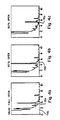
- Figure 3 shows a signal trace 56, generated by the first transducer 50 in accordance with the first embodiment.
- the vertical axis 58 corresponds to reflected wave amplitude and the horizontal axis 60 is the time delay between the transmittal of the wave and the receipt of the reflected wave.
- the first transducer 50 When the closure member 30 is at the valve seat 28, the first transducer 50 generates a trace 56 in which the initial reflection 62 is due to the valve near wall 54 on which the transducer is mounted.
- the peak 64 represents the wave reflected from the disk 32. Other, smaller peaks are reflections from other structures within the body and are to be ignored.
- the peak at 66 represents the wave reflected from the back wall 68 on the other side of the valve body ( Figure 2).
- the technician operating the equipment can more easily interpret the traces by having a drawing of the valve interior, but it is within the ordinary skill of ultrasound technicians to set up and operate the equipment and interpret the traces in accordance with the teachings herein.
- traces can be saved and compared from inspection to inspection, to identify discrepancies after taking into account differences in test equipment and other uncertainties. Also, a given valve type would have a characteristic trace in the open and closed conditions which may be utilized to interpret the traces for a particular valve of that type installed in the field.
- the second, stationary transducer 52 alone could be used for obtaining traces of the reflection of the disk 32 as the disk is moved between a fully opened and a fully closed position using the valve 18 or other flow control device upstream of the check valve 14.
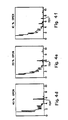
- Figures 4a - 4f represent traces from a second transducer mounted as shown in Figure 2.
- the initial reflection 70 is visible as a thick reflection at a time delay of about one unit and the disk reflection 72a is observed at approximately 31 ⁇ 2 time units.
- the spike 72b due to reflection of the disk has moved to about 41 ⁇ 2 time units.
- the disk reflection 72a through 72f is delayed longer and longer so that, when the valve is open less than 10%, the reflected delay 72f is at approximately seven time units.
- the traces are continuously visible on the operator's oscilloscope so that the movement of the disk spike 72 would be unmistakeable.
- both transducers 50,52 are utilized.
- the first transducer 50 is positioned initially as in the first embodiment adjacent the valve seat on the valve body surface and the second transducer is positioned on the exterior surface closest to the fully open position of the disk. In this embodiment, however, the first transducer 50 is moved along the body parallel to the arc of path 46 of disk 32 in increments corresponding to incremental positions of the disk 32 along path 46. The incremental positions of the disk 32 are controlled by the valve 18.
Landscapes
- Physics & Mathematics (AREA)
- Acoustics & Sound (AREA)
- Life Sciences & Earth Sciences (AREA)
- General Physics & Mathematics (AREA)
- Remote Sensing (AREA)
- Geology (AREA)
- Environmental & Geological Engineering (AREA)
- General Life Sciences & Earth Sciences (AREA)
- Engineering & Computer Science (AREA)
- Geophysics (AREA)
- Examining Or Testing Airtightness (AREA)
- Testing Of Devices, Machine Parts, Or Other Structures Thereof (AREA)
- Investigating Or Analyzing Materials By The Use Of Ultrasonic Waves (AREA)
- Length Measuring Devices Characterised By Use Of Acoustic Means (AREA)
Applications Claiming Priority (2)
| Application Number | Priority Date | Filing Date | Title |
|---|---|---|---|
| US2752787A | 1987-03-18 | 1987-03-18 | |
| US27527 | 1987-03-18 |
Publications (3)
| Publication Number | Publication Date |
|---|---|
| EP0282774A2 true EP0282774A2 (fr) | 1988-09-21 |
| EP0282774A3 EP0282774A3 (en) | 1990-02-28 |
| EP0282774B1 EP0282774B1 (fr) | 1994-01-05 |
Family
ID=21838248
Family Applications (1)
| Application Number | Title | Priority Date | Filing Date |
|---|---|---|---|
| EP88102656A Expired - Lifetime EP0282774B1 (fr) | 1987-03-18 | 1988-02-24 | Contrôle ultrasonore d'une valve |
Country Status (5)
| Country | Link |
|---|---|
| US (1) | US4920802A (fr) |
| EP (1) | EP0282774B1 (fr) |
| JP (1) | JPS63314438A (fr) |
| KR (1) | KR920002851B1 (fr) |
| DE (1) | DE3886792T2 (fr) |
Cited By (3)
| Publication number | Priority date | Publication date | Assignee | Title |
|---|---|---|---|---|
| EP0489596A1 (fr) * | 1990-12-06 | 1992-06-10 | B&W NUCLEAR TECHNOLOGIES, INC. | Surveillance de soupapes d'arrêt |
| EP0489597A3 (en) * | 1990-12-06 | 1993-04-21 | B&W Nuclear Service Company | Vibration monitoring methods and apparatus |
| GB2282434A (en) * | 1993-10-01 | 1995-04-05 | Btr Plc | Ball valve assembly |
Families Citing this family (32)
| Publication number | Priority date | Publication date | Assignee | Title |
|---|---|---|---|---|
| US5154080A (en) * | 1986-10-29 | 1992-10-13 | Westinghouse Electric Corp. | Integrated check valve testing system |
| US5027644A (en) * | 1990-03-09 | 1991-07-02 | Institute Of Gas Technology | Method and apparatus for injecting acoustic signals into live gas mains |
| US5257208A (en) * | 1990-04-23 | 1993-10-26 | Fire & Safety Electronics Inc. | Computerized portable testing device for backflow valves |
| US5115672A (en) * | 1991-02-11 | 1992-05-26 | Westinghouse Electric Corp. | System and method for valve monitoring using pipe-mounted ultrasonic transducers |
| US5228342A (en) * | 1991-07-26 | 1993-07-20 | Westinghouse Electric Corp. | Ultrasonic position sensor and method |
| DE4227657A1 (de) * | 1992-08-21 | 1994-02-24 | Hydac Technology Gmbh | Ultraschall-Prüfeinrichtung für Gasdruckspeicher |
| US7111491B2 (en) * | 2001-09-08 | 2006-09-26 | Ashcroft Inc. | Portable differential pressure generator |
| US20040206154A1 (en) * | 2002-05-16 | 2004-10-21 | Kosh William Stephen | Portable differential pressure generator |
| US6672130B2 (en) * | 2001-09-08 | 2004-01-06 | Dresser, Inc. | Pressure generator for portable instrument |
| US20070204917A1 (en) * | 2006-03-01 | 2007-09-06 | Rain Bird Corporation | Backflow prevention device |
| US20070204916A1 (en) * | 2006-03-01 | 2007-09-06 | Rain Bird Corporation | Backflow prevention device |
| US8904873B2 (en) * | 2010-12-10 | 2014-12-09 | Ihi Southwest Technologies, Inc. | Visualization of tests on swing type check valve using phased array sequence scanning |
| US9952182B2 (en) | 2010-12-10 | 2018-04-24 | Ihi Southwest Technologies | Visualization of tests on lift-type check valves using phased array sequence scanning |
| US9557303B2 (en) | 2010-12-10 | 2017-01-31 | Ihi Southwest Technologies, Inc. | Visualization of tests on swing type check valves using phased array sequence scanning |
| US10352477B2 (en) | 2010-12-10 | 2019-07-16 | Ihi Southwest Technologies, Inc. | Visualization of tests on globe-type valves using phased array sequence scanning |
| US8453508B2 (en) * | 2010-12-10 | 2013-06-04 | Ihi Southwest Technologies, Inc. | Testing of swing type check valves using phased array sequence scanning |
| JP6289195B2 (ja) * | 2014-03-20 | 2018-03-07 | 原子燃料工業株式会社 | スイング逆止弁の弁棒減肉診断方法 |
| EP3517185A1 (fr) * | 2018-01-29 | 2019-07-31 | Marioff Corporation OY | Ensemble de soupape |
| JP7056403B2 (ja) | 2018-06-20 | 2022-04-19 | 横河電機株式会社 | バルブ診断装置、バルブ装置、及びバルブ診断方法 |
| US10914412B2 (en) | 2018-06-28 | 2021-02-09 | Watts Regulator Co. | Backflow prevention assembly having a variable lay-length and orientation |
| USD944366S1 (en) | 2019-03-08 | 2022-02-22 | Watts Industries Italia S.R.L. | Static balancing valve |
| EP3705866B1 (fr) | 2019-03-08 | 2023-09-20 | WATTS INDUSTRIES ITALIA S.r.l. | Capteur de pression différentielle à cadran magnétique |
| US11815424B2 (en) | 2019-05-08 | 2023-11-14 | Watts Regulator Co. | Backflow prevention system test cock with a fluid sensor |
| US11795666B2 (en) | 2019-05-08 | 2023-10-24 | Watts Regulator Co. | Wireless communication system within a mechanical room |
| EP3748210B1 (fr) * | 2019-06-07 | 2023-01-04 | Focus-On V.O.F. | Organe d'arrêt pour un fluide |
| EP3835494A1 (fr) | 2019-12-10 | 2021-06-16 | Watts Regulator Co. | Système de surveillance de l'état d'un disconnecteur hydraulique |
| US12195954B2 (en) | 2019-12-10 | 2025-01-14 | Watts Regulator Co. | System for monitoring backflow preventer condition |
| US11585076B2 (en) | 2020-01-24 | 2023-02-21 | Watts Regulator Co. | Apparatus and method for valve cartridge extraction |
| US11773992B2 (en) | 2020-08-17 | 2023-10-03 | Watts Regulator Co. | Backflow prevention assembly with a linkage |
| US11719352B2 (en) | 2020-08-17 | 2023-08-08 | Watts Regulator Co. | Check cover assemblies for backflow prevention assemblies with integrated test cock protection shroud |
| US11739507B2 (en) | 2020-12-09 | 2023-08-29 | Watts Regulator Co. | Test cock with integrated extraction tool |
| USD1021000S1 (en) | 2021-08-17 | 2024-04-02 | Watts Regulator Co. | Valve assembly and body for same |
Family Cites Families (5)
| Publication number | Priority date | Publication date | Assignee | Title |
|---|---|---|---|---|
| US3455532A (en) * | 1965-09-15 | 1969-07-15 | Monsanto Co | Electropneumatic valve positioner |
| GB1525720A (en) * | 1975-12-20 | 1978-09-20 | Univ Cardiff | Distance measuring apparatus |
| FR2478255A1 (fr) * | 1980-03-11 | 1981-09-18 | Electricite De France | Dispositif de detection par ultrasons de fermeture d'un clapet |
| US4543649A (en) * | 1983-10-17 | 1985-09-24 | Teknar, Inc. | System for ultrasonically detecting the relative position of a moveable device |
| US4678621A (en) * | 1984-03-29 | 1987-07-07 | Combustion Engineering, Inc. | Method and means for monitoring the continuity of a fluid-filled network of conduits and valves |
-
1988
- 1988-02-24 EP EP88102656A patent/EP0282774B1/fr not_active Expired - Lifetime
- 1988-02-24 DE DE3886792T patent/DE3886792T2/de not_active Expired - Fee Related
- 1988-03-18 JP JP63063717A patent/JPS63314438A/ja active Granted
- 1988-03-18 KR KR1019880002850A patent/KR920002851B1/ko not_active Expired
- 1988-08-05 US US07/229,788 patent/US4920802A/en not_active Expired - Fee Related
Cited By (3)
| Publication number | Priority date | Publication date | Assignee | Title |
|---|---|---|---|---|
| EP0489596A1 (fr) * | 1990-12-06 | 1992-06-10 | B&W NUCLEAR TECHNOLOGIES, INC. | Surveillance de soupapes d'arrêt |
| EP0489597A3 (en) * | 1990-12-06 | 1993-04-21 | B&W Nuclear Service Company | Vibration monitoring methods and apparatus |
| GB2282434A (en) * | 1993-10-01 | 1995-04-05 | Btr Plc | Ball valve assembly |
Also Published As
| Publication number | Publication date |
|---|---|
| DE3886792T2 (de) | 1994-06-16 |
| US4920802A (en) | 1990-05-01 |
| EP0282774B1 (fr) | 1994-01-05 |
| JPH0563738B2 (fr) | 1993-09-13 |
| KR920002851B1 (ko) | 1992-04-06 |
| KR880011580A (ko) | 1988-10-29 |
| DE3886792D1 (de) | 1994-02-17 |
| JPS63314438A (ja) | 1988-12-22 |
| EP0282774A3 (en) | 1990-02-28 |
Similar Documents
| Publication | Publication Date | Title |
|---|---|---|
| EP0282774B1 (fr) | Contrôle ultrasonore d'une valve | |
| EP1697698B1 (fr) | Diagnostic de conduite de transmission d'impulsions dans un procede industriel | |
| EP0372700B1 (fr) | Moniteur pour le niveau d'un fluide | |
| US5154080A (en) | Integrated check valve testing system | |
| US5257545A (en) | Method and apparatus to monitor check valves | |
| US5329956A (en) | Pneumatic operated valve stroke timing | |
| US10352744B2 (en) | Chordal gas flow meter with transducers installed outside the pressure boundary | |
| US5426980A (en) | Booted ultrasonic transducer | |
| US5437194A (en) | Ultrasonic transducer system with temporal crosstalk isolation | |
| US4977778A (en) | Check valve testing system | |
| US5159835A (en) | Check valve testing system | |
| WO2000052442A1 (fr) | Procede et appareil determiner et quantifier des fuites de joints dans des valves d'arret de secours mises en place ou autres, pendant la production ou pendant l'arret | |
| JP3192429B2 (ja) | ガス減圧装置の試験に用いられる装置及び方法 | |
| US8739630B2 (en) | Pulse-echo method for determining the damping block geometry | |
| KR101695664B1 (ko) | 위상 배열 시퀀스 스캐닝을 이용한 스윙형 체크 밸브 테스트 | |
| US9952182B2 (en) | Visualization of tests on lift-type check valves using phased array sequence scanning | |
| CA1297577C (fr) | Methode de controle de composants mobiles | |
| US10352477B2 (en) | Visualization of tests on globe-type valves using phased array sequence scanning | |
| JPH0332020B2 (fr) | ||
| CA1321261C (fr) | Systeme d'essai de clapets de retenue | |
| US9557303B2 (en) | Visualization of tests on swing type check valves using phased array sequence scanning | |
| Au-Yang | Acoustic and ultrasonic signals as diagnostic tools for check valves | |
| EP0042212A1 (fr) | Localisation d'une fuite dans un pipeline | |
| EP0489596A1 (fr) | Surveillance de soupapes d'arrêt | |
| JP3030132B2 (ja) | 弁シート面の漏洩診断法 |
Legal Events
| Date | Code | Title | Description |
|---|---|---|---|
| PUAI | Public reference made under article 153(3) epc to a published international application that has entered the european phase |
Free format text: ORIGINAL CODE: 0009012 |
|
| AK | Designated contracting states |
Kind code of ref document: A2 Designated state(s): CH DE LI SE |
|
| PUAL | Search report despatched |
Free format text: ORIGINAL CODE: 0009013 |
|
| RHK1 | Main classification (correction) |
Ipc: F16K 37/00 |
|
| AK | Designated contracting states |
Kind code of ref document: A3 Designated state(s): CH DE LI SE |
|
| 17P | Request for examination filed |
Effective date: 19900725 |
|
| 17Q | First examination report despatched |
Effective date: 19910917 |
|
| GRAA | (expected) grant |
Free format text: ORIGINAL CODE: 0009210 |
|
| AK | Designated contracting states |
Kind code of ref document: B1 Designated state(s): CH DE LI SE |
|
| PGFP | Annual fee paid to national office [announced via postgrant information from national office to epo] |
Ref country code: DE Payment date: 19940204 Year of fee payment: 7 |
|
| PGFP | Annual fee paid to national office [announced via postgrant information from national office to epo] |
Ref country code: CH Payment date: 19940214 Year of fee payment: 7 |
|
| PGFP | Annual fee paid to national office [announced via postgrant information from national office to epo] |
Ref country code: SE Payment date: 19940217 Year of fee payment: 7 |
|
| REF | Corresponds to: |
Ref document number: 3886792 Country of ref document: DE Date of ref document: 19940217 |
|
| PLBE | No opposition filed within time limit |
Free format text: ORIGINAL CODE: 0009261 |
|
| STAA | Information on the status of an ep patent application or granted ep patent |
Free format text: STATUS: NO OPPOSITION FILED WITHIN TIME LIMIT |
|
| 26N | No opposition filed | ||
| EAL | Se: european patent in force in sweden |
Ref document number: 88102656.1 |
|
| PG25 | Lapsed in a contracting state [announced via postgrant information from national office to epo] |
Ref country code: SE Effective date: 19950225 |
|
| PG25 | Lapsed in a contracting state [announced via postgrant information from national office to epo] |
Ref country code: LI Effective date: 19950228 Ref country code: CH Effective date: 19950228 |
|
| PG25 | Lapsed in a contracting state [announced via postgrant information from national office to epo] |
Ref country code: DE Effective date: 19951101 |
|
| EUG | Se: european patent has lapsed |
Ref document number: 88102656.1 |