EP0282791A2 - Distributeur pour produits pâteux - Google Patents
Distributeur pour produits pâteux Download PDFInfo
- Publication number
- EP0282791A2 EP0282791A2 EP88102890A EP88102890A EP0282791A2 EP 0282791 A2 EP0282791 A2 EP 0282791A2 EP 88102890 A EP88102890 A EP 88102890A EP 88102890 A EP88102890 A EP 88102890A EP 0282791 A2 EP0282791 A2 EP 0282791A2
- Authority
- EP
- European Patent Office
- Prior art keywords
- dispenser according
- tube
- ceiling
- housing
- wall
- Prior art date
- Legal status (The legal status is an assumption and is not a legal conclusion. Google has not performed a legal analysis and makes no representation as to the accuracy of the status listed.)
- Granted
Links
Images


Classifications
-
- B—PERFORMING OPERATIONS; TRANSPORTING
- B65—CONVEYING; PACKING; STORING; HANDLING THIN OR FILAMENTARY MATERIAL
- B65D—CONTAINERS FOR STORAGE OR TRANSPORT OF ARTICLES OR MATERIALS, e.g. BAGS, BARRELS, BOTTLES, BOXES, CANS, CARTONS, CRATES, DRUMS, JARS, TANKS, HOPPERS, FORWARDING CONTAINERS; ACCESSORIES, CLOSURES, OR FITTINGS THEREFOR; PACKAGING ELEMENTS; PACKAGES
- B65D83/00—Containers or packages with special means for dispensing contents
- B65D83/76—Containers or packages with special means for dispensing contents for dispensing fluent contents by means of a piston
- B65D83/765—Containers or packages with special means for dispensing contents for dispensing fluent contents by means of a piston the piston being a follower-piston and the dispensing means comprising a hand-operated pressure device at the opposite part of the container
Definitions
- the invention relates to a dispenser for pasty masses, with a housing in which a piston which can only be displaced in the direction of emptying is arranged and which has an external handle for actuating a pump wall which can be pressed in the direction of the piston for dispensing the contents from an outlet opening of a top cover of the housing, which ceiling is connected to the pump wall by a tube.
- a donor of this type is known from DE-OS 34 16 999 of the applicant.
- the ceiling forms the actuation handle and at the same time the application area that spreads the pasty content, for which purpose the ceiling is dome-shaped.
- the piston is retightened over the level column. This retraction of the piston occurs primarily, i. H. before the remaining amount in the tube, which acts like a stopper, could compensate for the vacuum in the dispenser head.
- the pasty mass itself forms the valve.
- the object of the invention is therefore to design a generic dispenser in a technically simple, advantageous manner in such a way that the operating hand no longer comes into contact with the dispensed material when actuated.
- a generic dispenser of increased utility value is created: the unpleasant smearing of the operating hand and thus also the operating area of the dispenser no longer occurs.
- the acceptance is increased.
- the structural means are simple and functional.
- the procedure is such that the actuating handle is now designed as a key which can be moved transversely to the top of the ceiling and is arranged between the pump wall and the ceiling, the displacement movement of which, diverted by 90 °, is translated into a downward movement of the tube and thus of the wall.
- the mechanics in this regard lie in a length section required anyway for the special valve function of the tube. This is therefore used to the best advantage.
- the further measure has the effect that the displacement movement of the key is redirected by means of a fixed-mounted angle lever.
- Favorable leverage ratios with the shortest stroke distance can also be used here.
- a production-favorable training is achieved by a material uniformity between the button and the angle lever and by forming a film hinge between the two. Accordingly, sufficient tough or flexible plastic material is assumed.
- the upper When actuated the rim of the tube lifts off from the underside of the blanket and the outlet opening of the blanket is offset to the side of the tube, the upper end section of the tube being designed as a piston which sealingly runs in a cylinder formed by a collar on the underside of the blanket.
- the collar has a stiffening effect with respect to the ceiling - it is also achieved with regard to the hydraulic system that when the pump is pressed out, a continuously increasing prechamber forms in front of the tube mouth.
- the mass overlying the tube end is, on the one hand, squeezed out completely when the piston, which is designed as a tube, returns.
- the covering amount prevents the intake of false air.
- a second sealing point is also created in that the underside of the ceiling has a knob that closes and enters the mouth of the tube.
- the ceiling is formed by the bottom of a pot, the wall of which has an opening for the button and carries the pivot pin for the angle lever.
- the hinge pin it can be a stub shaft which is formed in the same way on the angle lever and which can be assigned by means of a corresponding oblique cut of the end faces by means of the clip connection, or a separate axis.
- a cheap, captive assignment of the pot is achieved in that the wall of the same is clipped over an annular rib of the housing.
- the invention also proposes that one leg of the angle lever encompasses the tube in a fork shape and forms crowned pressure runners on the underside. As a result of the fork shape, the actuating handle can thus be slipped onto the side of the tube, that is to say the base forming the ceiling must be connected to the housing beforehand.
- the spherical shape of the pressure runners promotes smooth operation and takes account of the attachment that is displaced in the swivel plane.
- a rotation lock between the pot wall and the housing. Lateral loads can thus be effectively kept away from the operating handle.
- a rotation lock can be realized, for example, by means of ribs / groove engagement, which means would have to be aligned axially.
- a structurally simplified closure device also results from the fact that a plug projecting into the ceiling-side outlet opening is arranged in the ceiling-side opening of the tube channel and is connected to the tube via radial gap-free radial webs.
- a stopper body so freely “suspended" in the dispensing path has a high sealing effect due to its arrangement which can be moved within limits; he can optimally adjust himself to tolerance deviations.
- the procedure is that the plug body has the shape of a double-cone frustum, from the base of which the radial webs originate.
- One truncated cone engages in the corresponding outlet opening in the closed position of the dispenser, while the other acts like a distribution cone, so that an equal supply of the medium to be dispensed takes place with respect to the annular gap sections.
- the invention further suggests that the longitudinal axis of the plug body coincides with the longitudinal central axis of the dispenser.
- an advantageous embodiment is achieved by an end stop of the key. After exercising the full stroke, this strikes against the corresponding end stop means on the housing.
- the latter are advantageously formed by the end faces of the dispenser facing the button side of two bearing tabs of the dispenser that support the button axis. The bearing rags therefore have an additional function.
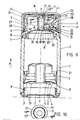
- the cylindrical housing 1 of the dispenser contains a piston 2. Its oppositely aligned edge lips 2 ⁇ lead to the cylindrical housing inner wall 1 ⁇ .
- the housing 1 is closed at the bottom by a base part 3 ⁇ forming bottom part 3.
- the latter is formed on an inner collar 3 ', which extends with its end face so far into the housing 1 that it extends directly to the piston 2.
- the base part 3 has a central opening 4 for air compensation during the upward piston displacement.
- the housing 1 is filled with the dispenser head pointing downwards. So that the air trapped between the piston 2 and the product can escape, the initial area of the inner wall of the housing 1 ⁇ is longitudinally grooved at 1 ⁇ .
- the piston 2 can only be displaced in the direction of emptying (arrow x).
- it carries a so-called clamping module 5 in the form of a radially oriented prong 5 ⁇ having a star made of spring steel on its wide surface facing the end of the housing. Its diameter circumscribed by the spike ends is, brought into the plane, larger than the clear diameter of the housing 1, whereby the spike ends 5 ⁇ as inclined feet on the housing inner wall 1 ⁇ hook against the direction of the arrow x blocking.
- the housing 1 carries a resiliently resetting bellows-like pump wall 6, which can be pressed in the direction of the piston 2, for dispensing the pasty mass.
- the pump wall is slightly curved upwards and merges peripherally into a clamping ring 7.
- This clamping ring which is S-shaped in cross section, engages from below into an annular groove 8 in the housing 1.
- the annular groove 8 has longitudinal ribs which dig into the elastic material of the clamped clamping ring leg.
- the central area 6 ⁇ of the pump wall 6 is significantly thickened in relation to the concentrically adjoining highly flexible ring area, which then merges into the clamping ring 7, which is again thicker.
- the central pump wall area 6 ⁇ forms an upwardly directed tube 9.
- the latter has a cylindrical jacket wall.
- the upper end section of the tube is designed as a piston 10.
- the latter runs axially displaceably in a cylinder 11.
- the piston 10 carries ring ribs 12 formed on the jacket wall side. Two such ring ribs 12 are provided.
- the inner edge of the cylinder is chamfered.
- a co-directional beveling of the ring ribs 12 also has a favorable association effect.
- the cylinder 11 is formed on a ceiling 13 that overlaps the top opening O of the housing 1. It extends at an axial distance y above the pump wall 6.
- the spacing space created in this way bears the reference symbol R.
- the axial distance y corresponds approximately to the dimension of half the diameter of the housing 1.
- the ceiling 13 is a component, more precisely the bottom of a pot 14 clipped to the upper edge of the housing. Furthermore, the ceiling 13 is retracted slightly arched. It forms a stripping trough 15 in the center. In this stripping trough 15 there is an outlet opening 16 for the pasty mass.
- the diameter of the stripping trough 15 corresponds essentially to one of the Cover 13 formed on the underside of the collar, which holds the cylinder 11.
- the collar ends at the middle height of the space R between the ceiling 13 and the pump wall 6.
- a stopper 17 molded onto the tube 9 projects into the eccentrically located outlet opening 16.
- the stopper is conical with a taper on the outlet opening side.
- the passage opening 16 also has a corresponding flank shape.
- the top of the stopper 17 is level with the base of the stripping trough 15.
- a second seal is also provided. This is formed by a likewise eccentrically located, hemispherical knob 18. The latter extends from the ceiling 13 and enters into the mouth 19 ⁇ of the tube 9, more precisely into an axially directed tube channel 19, the other mouth 19 ⁇ of which leads to the storage space of the pasty mass is open.
- the dispensing path is released with the help of an operating handle provided in the dispenser head.
- a button T arranged in the space R between the pump wall 6 and the ceiling 13. This is displaced transversely to the longitudinal center axis zz of the dispenser, that is to say transversely to the top of the ceiling. Their horizontal displacement movement is diverted by 90 ° into a downward movement of the tube 9 and thus the pump wall 6 lying in the longitudinal central axis zz.
- the actuation position results from FIG. 3.
- the key T continues into a horizontally mounted angle lever 20 . It is a right angle of different leg lengths.
- the storage is made in the apex of the angle leg.
- the axis bears the reference numeral 21.
- molded-on stub axles can protrude beyond the angle leg width act that are clipped into openings in fixed bearing flaps.
- the axis 21 is designed to be insulated (see FIG. 4).
- Your bearing tabs 22 start from the opening-side edge of the housing 1.
- the niche-like indentations 23 of the otherwise circular housing edge also result from FIG. 4.
- the bearing tabs 22 there adjoin rectangular sections that run back into the wall area.
- the niche bottom is closed.
- the receiving shaft between the two parallel bearing tabs 22 is designated 25. Its walls are relatively flexible so that they can rebound when the axis 21 is assigned.
- a centering or run-up slope 26 is arranged in front of the axle cavities.
- Key T and angle leg 20 consist of a molded body, d. H. they are designed using the same material.
- a hinge point in the form of a film hinge 27 is implemented for converting the linear movement of the key T into the pivoting movement of the angle lever 20.
- the central web 28 of the key T has a multiple wall thickness;
- the legs 20 ⁇ and 20 ⁇ of the angle lever 20 are thicker than the point mentioned.
- a wedge-shaped incision 29 extends from the underside of the key land.
- the pot 14 For receiving the key T, the pot 14 has a window-shaped opening 30. This, like the actuating surface of the key body, has a circular design. It (30) lies in a wall-thickened area of the pot wall 14 ⁇ , so that there is an increased guide length for the displacement movement.
- the key T is in a circular niche 31 of the pot wall 14 ⁇ . However, the niche does not extend over the entire height of the pot wall; it ends at a distance from the lower edge of the pot. This creates a kind of window sill 32 che affects the opening 30. Upward, the pot 14 merges into a clear transverse curve.
- the outer surface of the T key is convex. Viewed in plan view, the curvature contour corresponds essentially to that of the pot wall 14 ⁇ .
- a rotation lock is implemented between the pot wall 14 ⁇ and the housing 1.
- the housing-side contribution consists of an axially directed rib 33.
- the latter engages in a form-fitting manner in an upwardly open longitudinal groove 34 or a shape-matched recess in the housing.
- two such anti-rotation areas are taken into account in a diametrically opposed position.
- the same relief also results from the special design of the angle lever 20, more precisely its longer leg 20 ⁇ pointing in the direction of the tube.
- This leg 20 ⁇ comprises the cylindrical tube 9 fork-shaped. Tilting of the angle lever is also avoided from the corresponding fork wrap.
- the fork legs are designated 35.
- the latter form on their underside in the swivel plane rounded pressure runners 36. These slide under a shifting support point on the stiffened ring zone of the pump wall 6 (see. Fig. 3).
- FIGS. 2 and 3 The tipping point between the pot 14 or its pot wall 14 ⁇ and the neck-like tapered end section of the housing 1 results from FIGS. 2 and 3.
- the neck has an outwardly directed annular rib 37, which is provided by a locking projection 38 on the inside of the pot wall 14 is undermined.
- Both functional parts form inclined flanks that facilitate clip assignment.
- the pot edge 14 ⁇ is supported on an annular shoulder 39 of the housing 1.
- the dispenser head carries a protective cap 40 which overlaps it. The latter is held in the clamping grip seat.
- a peripheral viewing window 41 in the neck area of the housing 1 serves as an empty display.
- the piston that finally moves in front of this viewing window can be colored red, for example.
- the corresponding reset has already been completed before the mass remaining in the tube or tube channel 19 could reach the inner mouth end 19 'as a "plug".
- the mass overlying the tube 9 and located in the cylinder space further favors this effect.
- the provision will also partially push it outwards.
- FIGS. 9 and 10 are fundamentally of the same structure, which is why the reference numbers, in part without repeated text, are used analogously.
- the difference to the previous embodiment is that in the ceiling-side mouth 19 ⁇ of the tube channel 19, the plug 17 is arranged centrally as the tube channel are.
- the stopper 17 projecting into the ceiling-side outlet opening 16 is connected to the inner wall of the tube via radial webs (17 ().
- the radial webs viewed in the circumferential direction, leave between them annular gap sections 19 ⁇ (FIG. 10), passing through them, the medium to be dispensed rinses the plug body to collect above it in the prechamber of the cylinder 11. From there it leaves the outlet opening 16 of the pot 14 centrally.
- the plug body has the shape of a double truncated cone. Its truncated cone protruding over the upper edge of the tube 9 forms the actual sealing plug 17. Its truncated cone pointing in the opposite direction and practically completely immersed in the interior of the tube, that is to say the tube channel 19, functions as a flow divider.
- the rotationally symmetrical structure leads to equal distribution relationships with respect to the individual annular gap sections 19 ⁇ between the radial webs 17 ⁇ . The latter start from the largest section of the stopper body, namely from the obtuse-angled edge of the back-to-back base of the double-cone frustum. The webs are essentially flush with the end face of the tube 9.
- the radial webs 17 ⁇ are distributed at equal angles. A division into three is preferably used.
- the bottom (ceiling 13) of the pot 14 extends in the cylinder area at a short distance from the corresponding end face of the tube 9.
- a certain restoring force of the plug body can be used, which thus engages the central inlet opening 16 with a preload, which is a forms the ring flank corresponding to the truncated cone angle.
- a preload which is a forms the ring flank corresponding to the truncated cone angle.
- the longitudinal axis of the plug body and the longitudinal central axis zz of the dispenser coincide.
- both dispenser types have an end stop for the T button.
- the housing-side end stop is simply formed by the end faces 22 ⁇ of the two bearing flaps 22 facing the key, which form the receiving shaft 25 for the key T and the bearing receptacles for the key axis 21.
- the design of the film hinge 27 differs from the film hinge 27 described above in that the cuts reducing the web width now originate not only from the underside but from both sides of the leg 20 ⁇ of the T key. Otherwise, the plate forming the button is stiffened by molding on the top and bottom, the plate with the leg 20 ⁇ stiffening struts. These extend outside the area of the bearing flap end faces 22 ⁇ .
Landscapes
- Engineering & Computer Science (AREA)
- Mechanical Engineering (AREA)
- Closures For Containers (AREA)
- Reciprocating Pumps (AREA)
- Formation And Processing Of Food Products (AREA)
Priority Applications (1)
| Application Number | Priority Date | Filing Date | Title |
|---|---|---|---|
| AT88102890T ATE66429T1 (de) | 1987-03-18 | 1988-02-26 | Spender fuer pastoese massen. |
Applications Claiming Priority (2)
| Application Number | Priority Date | Filing Date | Title |
|---|---|---|---|
| DE19873708713 DE3708713A1 (de) | 1987-03-18 | 1987-03-18 | Spender fuer pastoese massen |
| DE3708713 | 1987-03-18 |
Publications (3)
| Publication Number | Publication Date |
|---|---|
| EP0282791A2 true EP0282791A2 (fr) | 1988-09-21 |
| EP0282791A3 EP0282791A3 (en) | 1989-08-30 |
| EP0282791B1 EP0282791B1 (fr) | 1991-08-21 |
Family
ID=6323316
Family Applications (1)
| Application Number | Title | Priority Date | Filing Date |
|---|---|---|---|
| EP88102890A Expired - Lifetime EP0282791B1 (fr) | 1987-03-18 | 1988-02-26 | Distributeur pour produits pâteux |
Country Status (4)
| Country | Link |
|---|---|
| EP (1) | EP0282791B1 (fr) |
| AT (1) | ATE66429T1 (fr) |
| DE (3) | DE3708713A1 (fr) |
| ES (1) | ES2025716T3 (fr) |
Cited By (3)
| Publication number | Priority date | Publication date | Assignee | Title |
|---|---|---|---|---|
| EP0691284A3 (fr) * | 1994-07-06 | 1996-05-29 | Bramlage Gmbh | Distributeur pour masses pâteuses |
| EP0990594A1 (fr) * | 1998-09-23 | 2000-04-05 | Guala Dispensing S.P.A. | Dispositif de distribution de produits pâteux |
| DE102015111551A1 (de) | 2015-07-16 | 2017-01-19 | Rpc Bramlage Gmbh | Ausgabeeinrichtung für einen Fluidspender |
Families Citing this family (5)
| Publication number | Priority date | Publication date | Assignee | Title |
|---|---|---|---|---|
| DE58903718D1 (de) * | 1988-10-03 | 1993-04-15 | Plasco Sa | Als spender fuer pastoese produkte ausgebildete dose. |
| NL8900170A (nl) * | 1989-01-24 | 1990-08-16 | Douwe Egberts Tabaksfab | Doseerhouder. |
| DE4219474A1 (de) * | 1992-06-13 | 1993-12-16 | Katz Otto | Cremespender |
| DE4329808C2 (de) * | 1993-09-03 | 2003-03-27 | Alpla Werke | Selbstschließender Verschluß |
| GB2285487A (en) * | 1994-01-05 | 1995-07-12 | Bovel Henry E | Dispensers for viscous substances |
Family Cites Families (3)
| Publication number | Priority date | Publication date | Assignee | Title |
|---|---|---|---|---|
| US3870200A (en) * | 1973-05-14 | 1975-03-11 | Spatz Corp | Valveless dispenser for fluent masses |
| DE3416999A1 (de) * | 1984-05-09 | 1985-11-14 | Bramlage Gmbh, 2842 Lohne | Spender fuer pastoese massen |
| GB2182726B (en) * | 1985-11-09 | 1989-10-25 | Metal Box Plc | Dispensers for pasty or viscous products |
-
1987
- 1987-03-18 DE DE19873708713 patent/DE3708713A1/de not_active Withdrawn
-
1988
- 1988-02-26 EP EP88102890A patent/EP0282791B1/fr not_active Expired - Lifetime
- 1988-02-26 AT AT88102890T patent/ATE66429T1/de not_active IP Right Cessation
- 1988-02-26 DE DE8888102890T patent/DE3864288D1/de not_active Expired - Lifetime
- 1988-02-26 DE DE8816917U patent/DE8816917U1/de not_active Expired - Lifetime
- 1988-02-26 ES ES198888102890T patent/ES2025716T3/es not_active Expired - Lifetime
Cited By (5)
| Publication number | Priority date | Publication date | Assignee | Title |
|---|---|---|---|---|
| EP0691284A3 (fr) * | 1994-07-06 | 1996-05-29 | Bramlage Gmbh | Distributeur pour masses pâteuses |
| EP0990594A1 (fr) * | 1998-09-23 | 2000-04-05 | Guala Dispensing S.P.A. | Dispositif de distribution de produits pâteux |
| DE102015111551A1 (de) | 2015-07-16 | 2017-01-19 | Rpc Bramlage Gmbh | Ausgabeeinrichtung für einen Fluidspender |
| WO2017009481A2 (fr) | 2015-07-16 | 2017-01-19 | Rpc Bramlage Gmbh | Dispositif de distribution pour un distributeur de fluide |
| US10384857B2 (en) | 2015-07-16 | 2019-08-20 | Rpc Bramlage Gmbh | Dispensing device for a fluid dispenser |
Also Published As
| Publication number | Publication date |
|---|---|
| ES2025716T3 (es) | 1992-04-01 |
| EP0282791B1 (fr) | 1991-08-21 |
| EP0282791A3 (en) | 1989-08-30 |
| DE3864288D1 (de) | 1991-09-26 |
| ATE66429T1 (de) | 1991-09-15 |
| DE3708713A1 (de) | 1988-09-29 |
| DE8816917U1 (de) | 1991-03-28 |
Similar Documents
| Publication | Publication Date | Title |
|---|---|---|
| EP0036491B1 (fr) | Distributeur pour produits pâteux | |
| EP0194417B1 (fr) | Pompe de dosage avec soufflet de pompage pour bouteilles ou flacons similaires | |
| DE2623964C3 (de) | Drucktasten-Sprüheinrichtung | |
| DE3227112C2 (fr) | ||
| EP0144879B1 (fr) | Distributeur pour matériaux pâteux, notamment distributeur de pâtes dentifrices | |
| EP0309949A2 (fr) | Distributeur pour produits pâteux | |
| EP0053329B1 (fr) | Récipient pour distribuer en portions un produit de consistance pâteuse | |
| EP0179342B1 (fr) | Distributeur pour produits pâteux | |
| EP0282791B1 (fr) | Distributeur pour produits pâteux | |
| DE4004653A1 (de) | Fluessigkeitsspruehvorrichtung | |
| DE3828811A1 (de) | Dosier- und spraypumpe fuer fluessige und niederviskose stoffe | |
| DE8713197U1 (de) | Spender zur portionierten Ausgabe pastöser Massen | |
| DE69100582T2 (de) | Betätigungsvorrichtung für Ausgabeventil. | |
| EP0376097A2 (fr) | Distributeur-doseur d'un produit pâteux | |
| DE3716110A1 (de) | Spender fuer portionierten ausgabe pastoeser massen | |
| EP0345458A2 (fr) | Distributeur | |
| EP0184742B1 (fr) | Distributeur pour la décharge en portion unique de pastilles, pâtes ou similaires | |
| DE3512649A1 (de) | Spender | |
| EP3953053B1 (fr) | Distributeur de produits pâteux | |
| DE3347843A1 (de) | Mehrkomponenten-kartusche | |
| DE3701180C2 (fr) | ||
| DE8629681U1 (de) | Dosierpumpe mit Pumpenbalg | |
| DE3512650A1 (de) | Spender | |
| DE3713294A1 (de) | Spender | |
| DE3007954A1 (de) | Spender fuer insbesondere pastoese massen |
Legal Events
| Date | Code | Title | Description |
|---|---|---|---|
| PUAI | Public reference made under article 153(3) epc to a published international application that has entered the european phase |
Free format text: ORIGINAL CODE: 0009012 |
|
| AK | Designated contracting states |
Kind code of ref document: A2 Designated state(s): AT BE CH DE ES FR GB GR IT LI LU NL SE |
|
| PUAL | Search report despatched |
Free format text: ORIGINAL CODE: 0009013 |
|
| AK | Designated contracting states |
Kind code of ref document: A3 Designated state(s): AT BE CH DE ES FR GB GR IT LI LU NL SE |
|
| 17P | Request for examination filed |
Effective date: 19891115 |
|
| 17Q | First examination report despatched |
Effective date: 19901106 |
|
| GRAA | (expected) grant |
Free format text: ORIGINAL CODE: 0009210 |
|
| AK | Designated contracting states |
Kind code of ref document: B1 Designated state(s): AT BE CH DE ES FR GB GR IT LI LU NL SE |
|
| PG25 | Lapsed in a contracting state [announced via postgrant information from national office to epo] |
Ref country code: SE Effective date: 19910821 Ref country code: GR Free format text: LAPSE BECAUSE OF FAILURE TO SUBMIT A TRANSLATION OF THE DESCRIPTION OR TO PAY THE FEE WITHIN THE PRESCRIBED TIME-LIMIT Effective date: 19910821 |
|
| REF | Corresponds to: |
Ref document number: 66429 Country of ref document: AT Date of ref document: 19910915 Kind code of ref document: T |
|
| ET | Fr: translation filed | ||
| REF | Corresponds to: |
Ref document number: 3864288 Country of ref document: DE Date of ref document: 19910926 |
|
| ITF | It: translation for a ep patent filed | ||
| GBT | Gb: translation of ep patent filed (gb section 77(6)(a)/1977) | ||
| PG25 | Lapsed in a contracting state [announced via postgrant information from national office to epo] |
Ref country code: AT Effective date: 19920226 |
|
| PG25 | Lapsed in a contracting state [announced via postgrant information from national office to epo] |
Ref country code: LU Free format text: LAPSE BECAUSE OF NON-PAYMENT OF DUE FEES Effective date: 19920229 |
|
| REG | Reference to a national code |
Ref country code: ES Ref legal event code: FG2A Ref document number: 2025716 Country of ref document: ES Kind code of ref document: T3 |
|
| PLBE | No opposition filed within time limit |
Free format text: ORIGINAL CODE: 0009261 |
|
| STAA | Information on the status of an ep patent application or granted ep patent |
Free format text: STATUS: NO OPPOSITION FILED WITHIN TIME LIMIT |
|
| 26N | No opposition filed | ||
| PGFP | Annual fee paid to national office [announced via postgrant information from national office to epo] |
Ref country code: BE Payment date: 19990219 Year of fee payment: 12 |
|
| PGFP | Annual fee paid to national office [announced via postgrant information from national office to epo] |
Ref country code: CH Payment date: 19990224 Year of fee payment: 12 |
|
| PGFP | Annual fee paid to national office [announced via postgrant information from national office to epo] |
Ref country code: NL Payment date: 19990228 Year of fee payment: 12 |
|
| PG25 | Lapsed in a contracting state [announced via postgrant information from national office to epo] |
Ref country code: BE Free format text: LAPSE BECAUSE OF NON-PAYMENT OF DUE FEES Effective date: 20000228 |
|
| PG25 | Lapsed in a contracting state [announced via postgrant information from national office to epo] |
Ref country code: LI Free format text: LAPSE BECAUSE OF NON-PAYMENT OF DUE FEES Effective date: 20000229 Ref country code: CH Free format text: LAPSE BECAUSE OF NON-PAYMENT OF DUE FEES Effective date: 20000229 |
|
| BERE | Be: lapsed |
Owner name: BRAMLAGE G.M.B.H. Effective date: 20000228 |
|
| PG25 | Lapsed in a contracting state [announced via postgrant information from national office to epo] |
Ref country code: NL Free format text: LAPSE BECAUSE OF NON-PAYMENT OF DUE FEES Effective date: 20000901 |
|
| REG | Reference to a national code |
Ref country code: CH Ref legal event code: PL |
|
| NLV4 | Nl: lapsed or anulled due to non-payment of the annual fee |
Effective date: 20000901 |
|
| REG | Reference to a national code |
Ref country code: GB Ref legal event code: IF02 |
|
| PGFP | Annual fee paid to national office [announced via postgrant information from national office to epo] |
Ref country code: DE Payment date: 20021212 Year of fee payment: 16 |
|
| PGFP | Annual fee paid to national office [announced via postgrant information from national office to epo] |
Ref country code: GB Payment date: 20030203 Year of fee payment: 16 |
|
| PGFP | Annual fee paid to national office [announced via postgrant information from national office to epo] |
Ref country code: FR Payment date: 20030218 Year of fee payment: 16 |
|
| PGFP | Annual fee paid to national office [announced via postgrant information from national office to epo] |
Ref country code: ES Payment date: 20030224 Year of fee payment: 16 |
|
| PG25 | Lapsed in a contracting state [announced via postgrant information from national office to epo] |
Ref country code: GB Free format text: LAPSE BECAUSE OF NON-PAYMENT OF DUE FEES Effective date: 20040226 |
|
| PG25 | Lapsed in a contracting state [announced via postgrant information from national office to epo] |
Ref country code: ES Free format text: LAPSE BECAUSE OF NON-PAYMENT OF DUE FEES Effective date: 20040227 |
|
| PG25 | Lapsed in a contracting state [announced via postgrant information from national office to epo] |
Ref country code: DE Free format text: LAPSE BECAUSE OF NON-PAYMENT OF DUE FEES Effective date: 20040901 |
|
| GBPC | Gb: european patent ceased through non-payment of renewal fee |
Effective date: 20040226 |
|
| PG25 | Lapsed in a contracting state [announced via postgrant information from national office to epo] |
Ref country code: FR Free format text: LAPSE BECAUSE OF NON-PAYMENT OF DUE FEES Effective date: 20041029 |
|
| REG | Reference to a national code |
Ref country code: FR Ref legal event code: ST |
|
| PG25 | Lapsed in a contracting state [announced via postgrant information from national office to epo] |
Ref country code: IT Free format text: LAPSE BECAUSE OF NON-PAYMENT OF DUE FEES;WARNING: LAPSES OF ITALIAN PATENTS WITH EFFECTIVE DATE BEFORE 2007 MAY HAVE OCCURRED AT ANY TIME BEFORE 2007. THE CORRECT EFFECTIVE DATE MAY BE DIFFERENT FROM THE ONE RECORDED. Effective date: 20050226 |
|
| REG | Reference to a national code |
Ref country code: ES Ref legal event code: FD2A Effective date: 20040227 |