EP0282829B1 - Interrupteur horaire électrique avec support de programme pouvant être commuté d'un programme à intervalles de temps courts à un programme à intervalles de temps longs - Google Patents
Interrupteur horaire électrique avec support de programme pouvant être commuté d'un programme à intervalles de temps courts à un programme à intervalles de temps longs Download PDFInfo
- Publication number
- EP0282829B1 EP0282829B1 EP88103253A EP88103253A EP0282829B1 EP 0282829 B1 EP0282829 B1 EP 0282829B1 EP 88103253 A EP88103253 A EP 88103253A EP 88103253 A EP88103253 A EP 88103253A EP 0282829 B1 EP0282829 B1 EP 0282829B1
- Authority
- EP
- European Patent Office
- Prior art keywords
- coupling
- program
- term
- time switch
- ring
- Prior art date
- Legal status (The legal status is an assumption and is not a legal conclusion. Google has not performed a legal analysis and makes no representation as to the accuracy of the status listed.)
- Expired - Lifetime
Links
- 230000008878 coupling Effects 0.000 claims abstract description 75
- 238000010168 coupling process Methods 0.000 claims abstract description 75
- 238000005859 coupling reaction Methods 0.000 claims abstract description 75
- 230000007774 longterm Effects 0.000 claims description 28
- 238000007373 indentation Methods 0.000 claims 1
- 230000001360 synchronised effect Effects 0.000 abstract 1
- 210000003128 head Anatomy 0.000 description 6
- 210000002105 tongue Anatomy 0.000 description 4
- 238000006073 displacement reaction Methods 0.000 description 3
- 230000003442 weekly effect Effects 0.000 description 2
- 239000007822 coupling agent Substances 0.000 description 1
- 210000001061 forehead Anatomy 0.000 description 1
- 238000004519 manufacturing process Methods 0.000 description 1
- 230000002441 reversible effect Effects 0.000 description 1
Images
Classifications
-
- G—PHYSICS
- G04—HOROLOGY
- G04C—ELECTROMECHANICAL CLOCKS OR WATCHES
- G04C23/00—Clocks with attached or built-in means operating any device at preselected times or after preselected time-intervals
- G04C23/02—Constructional details
- G04C23/08—Programming means
Definitions
- the invention relates to an electric time switch with an analog time display and with a time-synchronized drive driven by a time-controlled drive, provided with program-oriented switching tabs, disc-shaped or ring-shaped program carrier, which by means of a switching device from a short-time program corresponding speed, for example one revolution in 24 hours , can be switched to a speed corresponding to a long-term program of, for example, one revolution in seven days and vice versa, and the switching tabs of which actuate a contact system, with a short or long-term program set on the program carrier appropriate scale ring is attachable.
- the changeover gear consists of two axially offset and concentric to each other and concentric to the axis of the program carrier and rotatably connected to the program carrier gears of different speeds and two interconnected axially displaceably arranged on a drive shaft rotatably arranged gears, optionally with one or the other gear of the program carrier can be brought into engagement by axial displacement. Because the switching of the drive speed of the program carrier takes place by an axial displacement of two interconnected gears and it must be ensured that in an axial intermediate position both of these displaceable gears must be out of engagement with the two gears of the program carrier at the same time, this known timer inevitably results in one relatively large axial Overall height.
- this known time switch it is also known to reversibly place a scale ring printed on both sides with scales on the scale carrier, which displays the set short-term or long-term program at the correct time and with which it is also possible to set the scale carrier to the correct time of day or Set the time of day of the week.
- the changeover gear is provided with a shift lock on this n time switch, which only permits switching in certain time settings of the program carrier or the analog time display. For this purpose, on the one hand, additional expenditure on components and, on the other hand, an additional complication of operation must be accepted.
- a multi-range switching device in particular for time switching devices, is already known (DE-PS 31 48 704), in which a rotating switching disk is permanently connected to the time switching device.
- two drive shafts are provided, which can optionally be switched to the switching disc by means of a coupling device.
- the coupling device is arranged coaxially to the switching disk.
- the clutch device is reversible or axially displaceable.
- the scale carrier is also a coupling agent. With this time switch, one and the same program carrier can be used for both programs running at different speeds.
- the invention has for its object to improve an electrical timer of the type mentioned by a special design of the switching device such that on the one hand a very flat design is made possible in the axial direction and that on the other hand switching from a program, ie from the weekly program to the daily program or vice versa can be carried out in a very simple manner and without the occurrence of an intervention change leading to time errors.
- the program carrier can be coupled by means of a coupling element which can be moved radially and can be set to different radii with one of two drive rings arranged concentrically to the axis of rotation of the program carrier, one drive ring with the speed corresponding to the short-term program and the other drive ring is driven at the speed corresponding to the long-term program.
- This switching device ensures on the one hand that when switching from long-term to short-term program and vice versa there are no gear change operations and thus no time errors can occur on the program carrier.
- the switchover can be carried out in a very simple manner from the front of the program carrier, without the latter itself having to be removed.
- the coupling member designed according to claim 3 has the advantage that it can be retrofitted to the program carrier and does not require pre-assembly.
- the design of the coupling member according to claim 4 is advantageous in that it combines the advantages of the coupling members designed according to claims 2 and 3.
- the long-term program comprises an integral multiple of the short-term program, for example if the long-term program has seven days and the short-term program comprises one day, it is advantageous if the drive ring corresponds to that of the long-term program.
- Speed is driven is designed according to claim 5. This makes it easier to switch from the short-term program to the long-term program insofar as the drive ring of the long-term program must be rotated by less than 1/7 of its circumference to reach the switchover position in which two coupling slots or coupling recesses of the two drive rings are radially aligned . In other words, to reach this switchover position, the drive ring of the long-term program must be rotated by an angle that corresponds to the time period of the short-term period.
- the embodiment of the invention according to claim 6 is also important insofar as it ensures that that the switchover takes place at the same time of day, ie that no time errors can occur during the switchover.
- the embodiment of the invention according to claim 7 is also important, by means of which it is also ensured that a scale ring provided with the scale of the long-term program can be angularly offset on the program carrier by a period corresponding to the short-term program.
- the embodiment of the invention according to claims 8 and 9 results on the one hand in the possibility of a simple interlocking connection between the coupling pin and the program carrier and on the other hand in a simple way to produce a correct angular position between the program carrier and the coupling pin. Due to the design of the invention according to claim 10, it is possible to connect the coupling pin form-fitting to the program carrier in a simple manner already during preassembly, and in addition, the coupling pin in the radial slot of the program carrier receives better guidance so that it can be adjusted more easily leaves.
- the scale ring designed according to claim 11 can be used in a simple manner for both programs, in that it is placed on the program carrier in such a way that the time scale assigned to the program that is switched on is on the face side is visible.
- the configuration according to claim 12 also ensures in a simple and reliable manner that the scale ring, irrespective of which program is currently set, assumes the correct angular position on the program carrier.
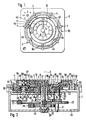
- the time switch shown has an essentially square housing 1 with a housing end wall 16. Coaxial with an axis 2 lying at the intersection of the square diagonals are outside the housing end wall 16 an analog indicator 3 and a switching tab that can be set up according to the program 4 programmable program carriers 50 arranged.
- the minute hand 6 sits on a minute shaft 7, which is arranged coaxially to the axis 2 and on which a hour tube 8 with an hour hand 9 is rotatably mounted in a known manner.
- the dial for this pointer movement is formed by an annular disk 10 provided with a cylindrical recess 11, which is non-rotatably fastened by means of a hub sleeve 12 in a centering collar 15 provided with locking tongues 13 and 14 of the housing end wall 16.
- the minute hand 6 is attached to the minute shaft 7 in a force-fitting or form-fitting manner by means of an integrally molded hub attachment 17, the hour hand 9 sits non-positively by means of a hollow hub 18, to which it is connected in one piece, on a cylindrical projection 19 of the hour tube 8 which is tapered in diameter.
- the hour tube 8 is rotatably mounted in a bore 21 of the housing end wall 16 by means of a second cylindrical extension 20.
- the minute shaft 7 is rotatably mounted in a journal bearing 28 of the rear wall 29 of the housing.
- the countershaft 23 is rigidly connected to a toothed pinion 30 arranged coaxially thereto and by means of a stub shaft 31 on the one hand in the rear wall 29 of the housing and by means of a cylindrical shoulder tapered in diameter 32 rotatably supported in a bearing bore 33 of the housing end wall 16.
- This pinion 30 is in engagement with the ring gear 34 of a first drive ring 35 which is rotatably guided on a centering ring 36 of the housing end wall 16 by means of a cylindrical collar 35 '.
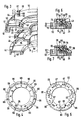
- the cross-sectional profiles of the two drive rings 35 and 41 can best be seen from FIG. 3.
- Both drive rings 35 and 41 each have a U-shaped, raised edge 43 and 44, the upper, plane-level boundary surfaces, as can be seen in FIG. 2, lie in the same axial plane. While the edge 43 of the drive ring 35 is only provided with a single coupling slot 45 which is open on the outside, the edge 44 of the drive ring 41 has a total of seven coupling slots 46 which are open inwards and are each arranged at equal angular intervals from one another. While the drive ring 35, which is driven directly by the pinion gear 30, makes a full revolution in 24 hours, the gear ring 39, which is in engagement with the pinion gear 39 of the gear wheel 38, rotates Drive ring 41 at a speed corresponding to one revolution in seven days.
- These two drive rings 35 and 41 are assigned a common, partly ring-shaped, partly disc-shaped program carrier 50, which has an annular groove 51 in the vicinity of its outer circumference and fine teeth 53 on the outside of an annular rib delimiting this annular groove 51 for non-positively receiving the switching riders 4.
- These switching tabs 4 can be fastened to the program carrier 50 in the manner indicated in FIGS. 1 and 2 and are provided for actuating a contact system of the time switch (not shown in the drawing) at the desired times.
- the program carrier 50 is guided concentrically to the axis 2 by means of a hub 55 between the centering ring 36 and the centering collar 15 of the housing end wall 16 and fixed in the axial direction by the locking tongues 13 and 14 of the centering collar 15.
- the latching tongues 13 and 14, as can be seen from FIG. 2, are provided with pawl-like hook profiles which project into a rabbet-like recess of the program carrier in a form-fitting manner.
- a flat ring section 56 Above the two edges 43 and 44 of the drive rings 35 and 41 is a flat ring section 56, which is provided with an inwardly open radial slot 57.
- This radial slot 57 extends over the total radial width of the two edges 43 and 44.
- a cylindrical coupling pin 58 is arranged, which has a tapered guide neck 59. The thickness of this guide neck 59 corresponds to the width of the radial slot 57 as far as this extends in the ring section 56.
- the coupling pin 58 is guided in the radial slot 57 in an almost movable manner in the axial direction.
- the part 62 of the radial slot lying below the ring section 56 is made wider, so that the coupling part 60 can be passed through it.
- the coupling pin 58 is inserted into the radial slot 57 in the course of a pre-assembly before the program carrier 50 itself is placed over the two drive rings.
- the coupling part 60 of the coupling pin 58 can either be inserted into the coupling slot 45 of the drive ring 35 or into one of the coupling slots 46 of the drive ring 41, so that the program carrier 50 either from the drive ring 35 with a drive speed of one revolution per day or from the drive ring 41 with one Revolution in seven days.
- the program carrier 50 is connected to the drive ring 35 of the short-term program, i.e. of the daily program, coupled.
- the position of the coupling pin 58 is shown in dash-dotted lines, in which the program carrier 50 is coupled to the drive ring 41 and is then driven at the rotational speed of the long-term program.
- a scale ring 65 which can be placed on the flat ring section 56 of the program carrier 50 is provided, which is shown in FIGS. 4 and 5 as an individual part with its two end views. While the 24-hour scale of the short-term or daily program is visible in FIG. 4, FIG. 5 shows the back with the 7-day scale of the long-term program.
- the scale ring is on its circumference 65 provided with seven rectangular incisions 66, into which latching tongues 64, which are integrally formed on the program carrier 50 but radially resiliently, can engage in a latching manner in order to fix the scale ring 65 on the program carrier 50.
- the scale ring 65 is additionally provided with a cylindrical bore 68, the diameter of which is matched to the diameter of the head part 61 of the coupling pin 58 and which lies on a radius which corresponds to the position of the coupling pin 58 when the program carrier 50 with the drive ring 35 of the short-term program.
- this bore 68 is continuous.
- the bores 69 can be designed as Sacck bores on the opposite side. Because the head part 61 of the coupling pin 58 projects into one of the bores 68 or 69 when the scale ring 65 is in place, the respective switching or coupling position is also of the coupling pin 58 secured in the radial direction. The switchover from the long-term program to the short-term program or vice versa can therefore only be done with the scale ring 65 removed by corresponding radial displacement of the coupling pin 58 in the radial slot 57.
- the scale ring 65 is then placed again on the program carrier 50 in the manner described, the bores 68 and 69 lying on different radii ensuring that the correct scale is visible in each case, because the bores 69 are only on the side of the scale ring 65 are arranged, on which the 24-hour scale is visible.
- FIG. 6 shows in a simplified manner how a plug-in pin 70 can be used as the coupling member instead of the radially displaceable coupling pin 58, which has a head part 71 which is larger in diameter.
- the program carrier 50 is provided with two plug-in bores 72 and 73 at the point where the radial slot 57 is located in the embodiment of FIGS. 1 to 3. Accordingly, the coupling slots 45 and 46 of the two drive rings 35 and 41 are replaced by plug holes 74 and 75, respectively.
- the diameter of the head part 71 is also matched to the bores 68 and 69 of the scale ring 65 so that it can be received by them.
- the switching takes place in such a way that the plug pin 70 with the scale ring 65 removed from the inside to the outside or from the outside to the inside is displaced so that it couples either the drive ring 35 or the drive ring 41 with the program carrier 50.
- a threaded pin could also be provided in an analogous manner, which can optionally be screwed into one of two threaded holes in the program carrier instead of the plug holes.
- the switching element consists of a two-armed rocker 78, which is pivotally mounted in a radial slot 79 of the program carrier 50 and either engages in a slot-shaped recess 80 in the edge 43 of the drive ring 35 in a form-fitting manner, or in the other position in a corresponding recess 81 in the collar 44 of the drive ring 41 engages in a coupling manner.
- Driver pins 82 and 83 are arranged on the top of the rocker, which depending on the position of the rocker 78 either protrude into the through bore 68 lying on the larger radius in this exemplary embodiment or else into one of the blind bores 69 of the scale ring 65 lying on the smaller radius.
- the coupling member which is formed by the rocker 78, is captively connected to the program carrier 50, as is the case with the exemplary embodiment in FIGS. 1 to 3.
Landscapes
- Physics & Mathematics (AREA)
- General Physics & Mathematics (AREA)
- Electromechanical Clocks (AREA)
- Measurement Of Predetermined Time Intervals (AREA)
- Electric Clocks (AREA)
Claims (12)
- Interrupteur horaire électrique avec une indication analogique de l'heure, et avec un support de programme en forme de disque ou d'anneau, entraîné par un mouvement d'horlogerie d'une manière synchrone, muni de curseurs placés conformément au programme, pouvant être commuté, au moyen d'un dispositif de commutation, d'une vitesse de rotation correspondante à un programme à intervalles de temps courts, d'une rotation en 24 heures par exemple, sur une vitesse de rotation correspondante à un programme à intervalles de temps longs, d'une rotation en sept jours par exemple, et inversement, et dont les curseurs actionnent un système de contacts, un anneau gradué, correspondant au programme à intervalles de temps courts ou longs, respectivement réglé, pouvant être placé sélectivement sur le support de programme, caractérisé en ce que le support de programme (50) peut être accouplé à l'un des deux anneaux de commande (35, 41), concentriques par rapport à l'axe de rotation (2) du support (50), au moyen d'un organe d'accouplement (58, 70, 78) mobile dans le sens radial et réglable sur différents rayons, l'un des anneaux de commande (35) étant entraîné à la vitesse de rotation, correspondante au programme à intervalles de temps courts, et l'autre anneau (41) étant entraîné à la vitesse, correspondante au programme à intervalles de temps longs.
- Interrupteur horaire suivant la revendication 1, caractérisé en ce que l'organe d'accouplement se compose d'un pivot (58) en saillie vers le bas, mobile dans une fente radiale (57) du support de programme (50), et qui peut être fixé dans deux positions radiales différentes, les deux anneaux de commande (35, 41) présentant respectivement des fentes d'accouplement (45, 46), ouvertes l'une par rapport à l'autre dans le sens radial, pour recevoir le tourillon de guidage (58).
- Interrupteur horaire suivant la revendication 1, caractérisé en ce que l'organe d'accouplement se compose d'un pivot d'emboîtement ou d'une goupille filetée (70), qui peuvent être logés dans l'un des deux trous d'emboîtement ou taraudages (72, 73) du support de programme (50), situés sur le même rayon vecteur, de manière à pénétrer dans un évidement d'accouplement (74) ou (75) de l'un des deux anneaux de commande (35) ou (41).
- Interrupteur horaire suivant la revendication 1, caractérisé en ce que l'organe d'accouplement se compose d'une bascule (78), logée avec une possibilité de pivotement dans une fente radiale (79) du support de programme (50), et qui s'engage dans un évidement d'accouplement (80) de l'un des anneaux de commande (35), dans l'une des deux positions de pivotement possibles, et dans un évidement d'accouplement (82) de l'autre anneau de commande (41), dans t'autre position de pivotement.
- Interrupteur horaire suivant l'une quelconque des revendications 2 à 4, caractérisé en ce que l'anneau de commande (41), entraîné à la vitesse de rotation correspondante au programme à intervalles de temps longs, présente un nombre de fentes d'accouplement (46) et/ou d'évidements d'accouplement (74, 81), disposés à distances angulaires égales, correspondant au nombre de fois suivant lequel la période du programme à intervalles de temps courts est comprise dans la période du programme à intervalles de temps longs.
- Interrupteur horaire suivant la revendication 5, caractérisé en ce que l'anneau de commande (35), entraîné à la vitesse de rotation correspondante au programme à intervalles de temps courts, présente une seule fente d'accouplement (45) et/ou un seul évidement d'accouplement (75, 80).
- Interrupteur horaire suivant l'une des revendications 5 et 6, caractérisé en ce que les fentes d'accouplement (46) et/ou les évidements d'accouplement (74, 81) de l'anneau de commande (41), tournant à la vitesse du programme à intervalles de temps longs, sont disposés de telle sorte, que la fente d'accouplement et/ou l'évidement d'accouplement (75, 80) de l'anneau de commande (35), tournant à la vitesse du programme à intervalles de temps courts, sont alignés dans le sens radial à ta même heure du jour.
- Interrupteur horaire suivant la revendication 2, caractérisé en ce que te pivot d'accouplement (58) présente un col de guidage (59) d'épaisseur réduite par rapport à sa section (60), qui dépasse vers le bas du support de programme (50).
- Interrupteur horaire suivant la revendication 8, caractérisé en ce que le pivot d'accouplement (58) présente un élément de tête (61), qui dépasse vers te haut de la fente radiale (57) du support de programme (50).
- Interrupteur horaire suivant ta revendication 9, caractérisé en ce que l'élément de tête (61) du pivot d'accouplement (58) présente une épaisseur supérieure à celle du col de guidage (59), adapté à la largeur de la fente radiale (57).
- Interrupteur horaire suivant l'une quelconque des revendications 1 à 10, caractérisé en ce que le support de programme (50) est muni d'un anneau gradué plat (65), qui présente une échelle de temps, correspondante au programme à intervalles de temps longs, sur l'une de ses deux surfaces annulaires, et une échelle de temps, correspondante au programme à intervalles de temps courts, sur l'autre surface annulaire, et qui peut s'enclencher sur le support de programme (50) d'une manière concentrique, avec une possibilité de démontage.
- Interrupteur horaire suivant la revendication 11, caractérisé en ce que l'anneau gradué (65) présente au moins deux orifices (68, 69) ou évidements, mutuellement alignés dans le sens radial, pour le logement et l'alignement ponctuels de l'élément de tête (61) du pivot d'accouplement (58) et/ou du pivot d'emboîtement ou de la goupille filetée (70), et/ou pour la réception adéquate de goupilles de centrage (82, 83) de la bascule (78).
Priority Applications (1)
| Application Number | Priority Date | Filing Date | Title |
|---|---|---|---|
| AT88103253T ATE76695T1 (de) | 1987-03-17 | 1988-03-03 | Elektrische schaltuhr mit einem von einem kurzzeitprogramm auf ein langzeitprogramm umschaltbaren programmtraeger. |
Applications Claiming Priority (2)
| Application Number | Priority Date | Filing Date | Title |
|---|---|---|---|
| DE3708611 | 1987-03-17 | ||
| DE3708611A DE3708611C1 (de) | 1987-03-17 | 1987-03-17 | Elektrische Schaltuhr mit einem von einem Kurzzeitprogramm auf ein Langzeitprogramm umschaltbaren Programmtraeger |
Publications (3)
| Publication Number | Publication Date |
|---|---|
| EP0282829A2 EP0282829A2 (fr) | 1988-09-21 |
| EP0282829A3 EP0282829A3 (en) | 1990-07-11 |
| EP0282829B1 true EP0282829B1 (fr) | 1992-05-27 |
Family
ID=6323262
Family Applications (1)
| Application Number | Title | Priority Date | Filing Date |
|---|---|---|---|
| EP88103253A Expired - Lifetime EP0282829B1 (fr) | 1987-03-17 | 1988-03-03 | Interrupteur horaire électrique avec support de programme pouvant être commuté d'un programme à intervalles de temps courts à un programme à intervalles de temps longs |
Country Status (5)
| Country | Link |
|---|---|
| US (1) | US4823329A (fr) |
| EP (1) | EP0282829B1 (fr) |
| AT (1) | ATE76695T1 (fr) |
| DE (1) | DE3708611C1 (fr) |
| ES (1) | ES2031542T3 (fr) |
Families Citing this family (5)
| Publication number | Priority date | Publication date | Assignee | Title |
|---|---|---|---|---|
| CH677057B5 (fr) * | 1987-10-01 | 1991-10-15 | Erard Raoul Henri | |
| US6274827B1 (en) | 1997-02-20 | 2001-08-14 | Martin Loffler | Manual timer switching device having a rotatable knob |
| JP2002333768A (ja) * | 2001-05-11 | 2002-11-22 | Sharp Corp | 現像方法および画像形成装置 |
| US6826127B2 (en) * | 2002-05-15 | 2004-11-30 | Albert Stekelenburg | Setting structure module for timer |
| US7072246B2 (en) * | 2003-05-20 | 2006-07-04 | Timex Group B.V. | Wearable electronic device with multiple ring indicia display |
Family Cites Families (7)
| Publication number | Priority date | Publication date | Assignee | Title |
|---|---|---|---|---|
| GB1399152A (en) * | 1972-03-02 | 1975-06-25 | Amf Inc | Time switches |
| US3864539A (en) * | 1974-02-19 | 1975-02-04 | Fred Hauser | Day and hour continuously cycling timing controller with adjustable cam actuators |
| DE2835518C2 (de) * | 1978-08-12 | 1988-09-29 | Theben-Werk Zeitautomatik Gmbh & Co Kg, 7452 Haigerloch | Elektrische Schaltuhr mit analoger Uhrzeitanzeige |
| DE2840690C2 (de) * | 1978-09-19 | 1982-11-04 | Theben-Werke Zeitautomatik GmbH, 7452 Haigerloch | Elektrische Schaltuhr mit einem Kurzzeit- und einem Langzeitprogrammträger |
| US4297546A (en) * | 1980-04-14 | 1981-10-27 | Amf Incorporated | Actuating means for switch operation in timing apparatus |
| DE8135821U1 (de) * | 1981-12-09 | 1986-01-02 | Dieter Gräßlin Feinwerktechnik, 7742 St. Georgen | Mehrbereichsschalteinrichtung |
| US4410774A (en) * | 1982-06-10 | 1983-10-18 | American Manufacturing Company, Inc. | Single knob variable range timer |
-
1987
- 1987-03-17 DE DE3708611A patent/DE3708611C1/de not_active Expired
-
1988
- 1988-03-03 AT AT88103253T patent/ATE76695T1/de not_active IP Right Cessation
- 1988-03-03 ES ES198888103253T patent/ES2031542T3/es not_active Expired - Lifetime
- 1988-03-03 EP EP88103253A patent/EP0282829B1/fr not_active Expired - Lifetime
- 1988-03-17 US US07/169,410 patent/US4823329A/en not_active Expired - Lifetime
Also Published As
| Publication number | Publication date |
|---|---|
| EP0282829A3 (en) | 1990-07-11 |
| ES2031542T3 (es) | 1992-12-16 |
| US4823329A (en) | 1989-04-18 |
| DE3708611C1 (de) | 1988-06-01 |
| ATE76695T1 (de) | 1992-06-15 |
| EP0282829A2 (fr) | 1988-09-21 |
Similar Documents
| Publication | Publication Date | Title |
|---|---|---|
| DE3832514C1 (fr) | ||
| DE2658105B2 (de) | Kontaktgesteuerter Impulsgenerator | |
| DE2619298C3 (de) | Datumskorrekturmechanismus für eine Uhr | |
| EP0082286B1 (fr) | Dispositif commutateur à plusieurs échelles | |
| DE2835518C2 (de) | Elektrische Schaltuhr mit analoger Uhrzeitanzeige | |
| EP0947894B1 (fr) | Dispositif de mise à l'heure pour montre | |
| EP0322511B1 (fr) | Indicateur de quantième | |
| DE3708611C1 (de) | Elektrische Schaltuhr mit einem von einem Kurzzeitprogramm auf ein Langzeitprogramm umschaltbaren Programmtraeger | |
| DE1673994A1 (de) | Mehrstufige Skalenanzeige | |
| DE8703986U1 (de) | Elektrische Schaltuhr mit einem von einem Kurzzeitprogramm auf ein Langzeitprogramm umschaltbaren Programmträger | |
| DE2213999C3 (de) | Kalenderuhr mit Tages- und Wochentagsanzeige | |
| DE2840690C2 (de) | Elektrische Schaltuhr mit einem Kurzzeit- und einem Langzeitprogrammträger | |
| DE2205139B2 (de) | Korrekturvorrichtung für eine Uhr mit mehreren Zeitanzeigen | |
| DE3325588C2 (de) | Schaltuhr mit einer sich drehenden Programmscheibe | |
| DE102018113535B4 (de) | Antriebseinrichtung | |
| CH716439B1 (de) | Uhr mit einer ersten Anzeige und einer zweiten Anzeige. | |
| EP1147532B1 (fr) | Minuterie pourvue d'un cylindre de commutation 24 heures | |
| DE2443614A1 (de) | Zifferblattscheibe fuer schaltuhren | |
| DE102007038202B3 (de) | 24-Stunden-Anzeige für eine Uhr mit Zeigern | |
| DE8107589U1 (de) | "Als Einschubkassette ausgebildete Schaltuhr" | |
| DE7824156U1 (de) | Elektrische Schaltuhr mit analoger Uhrzeitanzeige | |
| DE2361685C3 (de) | Datumsanzeige für eine Uhr | |
| DE2313309C3 (de) | Elektrische Schaltuhr | |
| DE8508296U1 (de) | Schaltuhr mit zwei Schaltreiter tragenden Programmschaltscheiben | |
| DE3025709A1 (de) | Schaltuhr |
Legal Events
| Date | Code | Title | Description |
|---|---|---|---|
| PUAI | Public reference made under article 153(3) epc to a published international application that has entered the european phase |
Free format text: ORIGINAL CODE: 0009012 |
|
| AK | Designated contracting states |
Kind code of ref document: A2 Designated state(s): AT BE CH ES FR GB IT LI NL SE |
|
| PUAL | Search report despatched |
Free format text: ORIGINAL CODE: 0009013 |
|
| AK | Designated contracting states |
Kind code of ref document: A3 Designated state(s): AT BE CH ES FR GB IT LI NL SE |
|
| 17P | Request for examination filed |
Effective date: 19900802 |
|
| 17Q | First examination report despatched |
Effective date: 19910805 |
|
| GRAA | (expected) grant |
Free format text: ORIGINAL CODE: 0009210 |
|
| AK | Designated contracting states |
Kind code of ref document: B1 Designated state(s): AT BE CH ES FR GB IT LI NL SE |
|
| REF | Corresponds to: |
Ref document number: 76695 Country of ref document: AT Date of ref document: 19920615 Kind code of ref document: T |
|
| ET | Fr: translation filed | ||
| GBT | Gb: translation of ep patent filed (gb section 77(6)(a)/1977) | ||
| ITF | It: translation for a ep patent filed | ||
| REG | Reference to a national code |
Ref country code: ES Ref legal event code: FG2A Ref document number: 2031542 Country of ref document: ES Kind code of ref document: T3 |
|
| PLBE | No opposition filed within time limit |
Free format text: ORIGINAL CODE: 0009261 |
|
| STAA | Information on the status of an ep patent application or granted ep patent |
Free format text: STATUS: NO OPPOSITION FILED WITHIN TIME LIMIT |
|
| 26N | No opposition filed | ||
| EAL | Se: european patent in force in sweden |
Ref document number: 88103253.6 |
|
| REG | Reference to a national code |
Ref country code: GB Ref legal event code: IF02 |
|
| REG | Reference to a national code |
Ref country code: CH Ref legal event code: PFA Free format text: THEBEN-WERK ZEITAUTOMATIK GMBH TRANSFER- THEBEN AG |
|
| NLS | Nl: assignments of ep-patents |
Owner name: THEBEN AG |
|
| REG | Reference to a national code |
Ref country code: ES Ref legal event code: PC2A |
|
| REG | Reference to a national code |
Ref country code: FR Ref legal event code: CJ Ref country code: FR Ref legal event code: CD |
|
| PGFP | Annual fee paid to national office [announced via postgrant information from national office to epo] |
Ref country code: ES Payment date: 20050307 Year of fee payment: 18 |
|
| PGFP | Annual fee paid to national office [announced via postgrant information from national office to epo] |
Ref country code: FR Payment date: 20050311 Year of fee payment: 18 Ref country code: AT Payment date: 20050311 Year of fee payment: 18 |
|
| PGFP | Annual fee paid to national office [announced via postgrant information from national office to epo] |
Ref country code: NL Payment date: 20050325 Year of fee payment: 18 |
|
| PGFP | Annual fee paid to national office [announced via postgrant information from national office to epo] |
Ref country code: CH Payment date: 20050331 Year of fee payment: 18 |
|
| PG25 | Lapsed in a contracting state [announced via postgrant information from national office to epo] |
Ref country code: AT Free format text: LAPSE BECAUSE OF NON-PAYMENT OF DUE FEES Effective date: 20060303 |
|
| PG25 | Lapsed in a contracting state [announced via postgrant information from national office to epo] |
Ref country code: ES Free format text: LAPSE BECAUSE OF NON-PAYMENT OF DUE FEES Effective date: 20060304 |
|
| PG25 | Lapsed in a contracting state [announced via postgrant information from national office to epo] |
Ref country code: CH Free format text: LAPSE BECAUSE OF NON-PAYMENT OF DUE FEES Effective date: 20060331 Ref country code: LI Free format text: LAPSE BECAUSE OF NON-PAYMENT OF DUE FEES Effective date: 20060331 |
|
| PG25 | Lapsed in a contracting state [announced via postgrant information from national office to epo] |
Ref country code: NL Free format text: LAPSE BECAUSE OF NON-PAYMENT OF DUE FEES Effective date: 20061001 |
|
| REG | Reference to a national code |
Ref country code: CH Ref legal event code: PL |
|
| NLV4 | Nl: lapsed or anulled due to non-payment of the annual fee |
Effective date: 20061001 |
|
| REG | Reference to a national code |
Ref country code: FR Ref legal event code: ST Effective date: 20061130 |
|
| PGFP | Annual fee paid to national office [announced via postgrant information from national office to epo] |
Ref country code: GB Payment date: 20070301 Year of fee payment: 20 Ref country code: BE Payment date: 20070301 Year of fee payment: 20 |
|
| PGFP | Annual fee paid to national office [announced via postgrant information from national office to epo] |
Ref country code: SE Payment date: 20070309 Year of fee payment: 20 |
|
| REG | Reference to a national code |
Ref country code: ES Ref legal event code: FD2A Effective date: 20060304 |
|
| PGFP | Annual fee paid to national office [announced via postgrant information from national office to epo] |
Ref country code: IT Payment date: 20070523 Year of fee payment: 20 |
|
| PG25 | Lapsed in a contracting state [announced via postgrant information from national office to epo] |
Ref country code: FR Free format text: LAPSE BECAUSE OF NON-PAYMENT OF DUE FEES Effective date: 20060331 |
|
| REG | Reference to a national code |
Ref country code: GB Ref legal event code: PE20 |
|
| BE20 | Be: patent expired |
Owner name: *THEBEN A.G. Effective date: 20080303 |
|
| EUG | Se: european patent has lapsed | ||
| PG25 | Lapsed in a contracting state [announced via postgrant information from national office to epo] |
Ref country code: GB Free format text: LAPSE BECAUSE OF EXPIRATION OF PROTECTION Effective date: 20080302 |