EP0282886A2 - Procédé de régulation de la température de départ dans une installation de transport de chaleur - Google Patents
Procédé de régulation de la température de départ dans une installation de transport de chaleur Download PDFInfo
- Publication number
- EP0282886A2 EP0282886A2 EP88103684A EP88103684A EP0282886A2 EP 0282886 A2 EP0282886 A2 EP 0282886A2 EP 88103684 A EP88103684 A EP 88103684A EP 88103684 A EP88103684 A EP 88103684A EP 0282886 A2 EP0282886 A2 EP 0282886A2
- Authority
- EP
- European Patent Office
- Prior art keywords
- flow
- temperature
- working medium
- energy
- circulating
- Prior art date
- Legal status (The legal status is an assumption and is not a legal conclusion. Google has not performed a legal analysis and makes no representation as to the accuracy of the status listed.)
- Granted
Links
Images


Classifications
-
- F—MECHANICAL ENGINEERING; LIGHTING; HEATING; WEAPONS; BLASTING
- F24—HEATING; RANGES; VENTILATING
- F24D—DOMESTIC- OR SPACE-HEATING SYSTEMS, e.g. CENTRAL HEATING SYSTEMS; DOMESTIC HOT-WATER SUPPLY SYSTEMS; ELEMENTS OR COMPONENTS THEREFOR
- F24D19/00—Details
- F24D19/10—Arrangement or mounting of control or safety devices
- F24D19/1006—Arrangement or mounting of control or safety devices for water heating systems
- F24D19/1009—Arrangement or mounting of control or safety devices for water heating systems for central heating
- F24D19/1012—Arrangement or mounting of control or safety devices for water heating systems for central heating by regulating the speed of a pump
-
- G—PHYSICS
- G05—CONTROLLING; REGULATING
- G05D—SYSTEMS FOR CONTROLLING OR REGULATING NON-ELECTRIC VARIABLES
- G05D23/00—Control of temperature
- G05D23/19—Control of temperature characterised by the use of electric means
- G05D23/1919—Control of temperature characterised by the use of electric means characterised by the type of controller
-
- Y—GENERAL TAGGING OF NEW TECHNOLOGICAL DEVELOPMENTS; GENERAL TAGGING OF CROSS-SECTIONAL TECHNOLOGIES SPANNING OVER SEVERAL SECTIONS OF THE IPC; TECHNICAL SUBJECTS COVERED BY FORMER USPC CROSS-REFERENCE ART COLLECTIONS [XRACs] AND DIGESTS
- Y02—TECHNOLOGIES OR APPLICATIONS FOR MITIGATION OR ADAPTATION AGAINST CLIMATE CHANGE
- Y02B—CLIMATE CHANGE MITIGATION TECHNOLOGIES RELATED TO BUILDINGS, e.g. HOUSING, HOUSE APPLIANCES OR RELATED END-USER APPLICATIONS
- Y02B30/00—Energy efficient heating, ventilation or air conditioning [HVAC]
- Y02B30/70—Efficient control or regulation technologies, e.g. for control of refrigerant flow, motor or heating
Definitions
- the invention relates to a method for controlling the flow temperature of the working medium of a plant for heat energy transmission, in particular for temperature control of the air in a closed space.
- a method is generally known in which the flow temperature of a heating system is controlled in accordance with the outside temperature.
- the intention is to adapt the heating output of the system to the constantly changing gradient between room temperature and outside temperature.
- this method is not able to take into account the heat storage capacity of the building masonry. This deficiency can lead to the fact that in the event of a fall in the weather after a longer heating period, the system is quickly brought to an increased heating capacity, although the heat stored in the masonry would initially allow the heating energy to be completely or at least partially dispensed with.
- a rapid rise in temperature after a long cold period leads to an equally rapid decrease in heating output, even though the masonry is still very cold and generally heats up much more slowly than the outside air.
- Outside temperature sensors have become known which are embedded in the masonry, but these sensors only detect the temperature of the masonry in its immediate vicinity giving. As a result, the meaningfulness of their measurements for the entire building complex is questionable.
- the invention is based on the object of specifying a method for controlling the flow temperature which takes into account secondary influences, for example heat stored in the masonry, and internal loads on the control of the energy requirement of a room.
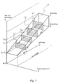
- the solution is to measure the flow of energy consumed in the working medium circuit and then determine the flow temperature in the working medium circuit using a system-specific three-dimensional block of characteristics, the dimensions of which are determined by the flow and return temperature as well as the circulating flow of the working medium in the system.
- a load level in the heating operation of a system results from the respective gradient between room temperature and outside temperature.
- a certain flow temperature is assigned to each load level.
- the actual heat loss flow in the heating circuit can be calculated for each load level from the difference between the flow and return temperatures as well as the circulating flow, which is therefore also assigned a specific flow temperature.
- the actual heat loss flow in the heating circuit is measured and the associated flow temperature is then determined in each case.
- the influences by the heat storage capacity of the masonry on the control of the flow temperature and the heating power of a system can be taken into account in full. This results in savings in heating energy and an increase in heating comfort.
- the weather sensor which is indispensable in conventional flow temperature control methods, including the measured value transmission lines, is no longer required.
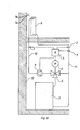
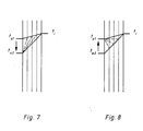
- the operation of the system according to FIG. 6 is as follows: It is assumed that the heating system has adjusted itself to an outside temperature t a1 on a mild winter day. The temperature gradient from t i to t a1 is small, as is the heat dissipation from heating surface 8. The product of the difference between the flow and return temperatures multiplied by the circulating volume flow corresponds to an integrated load level field within the system's characteristic curve block. If there is a drop in temperature from t a1 to t a2 ⁇ , then the heat stored in the masonry 12 is first consumed in layers from the outside, as is shown in simplified form in FIG. 7.
- the computer 4 now calculates the new, larger load step field on the basis of the new measured values of the sensors 1, 2 and 3 and shifts this within the stored characteristic curve block of the system towards a higher flow temperature until it can be fully integrated again.
- the setpoint value for the flow temperature that is automatically found and assigned to the new load level field is compared with the actual value measured by sensor 1.
- the computer 4 calculates an actuating signal which adjusts the mixing valve 5 via the motorized actuator 6 until the flow temperature corresponds to the new setpoint.
- the circulation pump 9 also receives a signal from the computer 4 for power adjustment, which is monitored on the basis of the measured values of the flow rate sensor 3.
- the layered heating of the masonry also takes a certain time. During this time, however, the heat output of the heating surfaces 8 also gradually decreases, as can be seen from the corresponding rise in the return temperature.
- the load level field becomes smaller and can be shifted in the direction of a lower flow temperature, which then results as a new setpoint when the new load level field is fully integrated in the characteristic block of the system.
- the mixing valve 5 and the circulation pump 9 are then controlled accordingly.
- the procedure is then basically the same, if the room temperature also changes due to internal loads.
- a decrease in the room temperature e.g. B. by ventilation, increases the temperature difference between flow and return and thus also the load level field, which is now shifted in the direction of a higher flow temperature.
- a warming of the room air e.g. by a larger number of people or by waste heat from non-heating devices, leads to a reduction in the temperature spread between flow and return and thus to a shift in the load level field in the direction of a lower flow temperature.
- the computer 4 controls the heat generator directly. Furthermore, the computer 4 takes into account their different specific heat when operating with media other than water. Moreover, it is easy to see that the invention is not only suitable for room air temperature control, but also for industrial heat consumers, for process engineering purposes and the like, i. H. for heating systems in the broadest sense. The process for cooling and air conditioning systems can also be easily reversed.
Landscapes
- Engineering & Computer Science (AREA)
- Physics & Mathematics (AREA)
- General Physics & Mathematics (AREA)
- Automation & Control Theory (AREA)
- Thermal Sciences (AREA)
- Chemical & Material Sciences (AREA)
- Combustion & Propulsion (AREA)
- Mechanical Engineering (AREA)
- General Engineering & Computer Science (AREA)
- Control Of Temperature (AREA)
- Steam Or Hot-Water Central Heating Systems (AREA)
- Central Heating Systems (AREA)
- Air Conditioning Control Device (AREA)
- Physical Or Chemical Processes And Apparatus (AREA)
- Heat Treatment Of Steel (AREA)
- Transmission Systems Not Characterized By The Medium Used For Transmission (AREA)
- Valve Device For Special Equipments (AREA)
- Domestic Hot-Water Supply Systems And Details Of Heating Systems (AREA)
- Feedback Control In General (AREA)
- Control Of Heat Treatment Processes (AREA)
- Liquid Developers In Electrophotography (AREA)
Priority Applications (1)
| Application Number | Priority Date | Filing Date | Title |
|---|---|---|---|
| AT88103684T ATE82630T1 (de) | 1987-03-19 | 1988-03-09 | Verfahren zum steuern der vorlauftemperatur einer anlage zur uebertragung von waermeenergie. |
Applications Claiming Priority (2)
| Application Number | Priority Date | Filing Date | Title |
|---|---|---|---|
| DE19873709085 DE3709085A1 (de) | 1987-03-19 | 1987-03-19 | Verfahren zum steuern der vorlauftemperatur einer heizungsanlage |
| DE3709085 | 1987-03-19 |
Publications (3)
| Publication Number | Publication Date |
|---|---|
| EP0282886A2 true EP0282886A2 (fr) | 1988-09-21 |
| EP0282886A3 EP0282886A3 (en) | 1988-11-30 |
| EP0282886B1 EP0282886B1 (fr) | 1992-11-19 |
Family
ID=6323538
Family Applications (1)
| Application Number | Title | Priority Date | Filing Date |
|---|---|---|---|
| EP88103684A Expired - Lifetime EP0282886B1 (fr) | 1987-03-19 | 1988-03-09 | Procédé de régulation de la température de départ dans une installation de transport de chaleur |
Country Status (8)
| Country | Link |
|---|---|
| US (1) | US4884743A (fr) |
| EP (1) | EP0282886B1 (fr) |
| JP (1) | JPH01119811A (fr) |
| CN (1) | CN1013065B (fr) |
| AT (1) | ATE82630T1 (fr) |
| DE (2) | DE3709085A1 (fr) |
| DK (1) | DK150388A (fr) |
| FI (1) | FI881313L (fr) |
Cited By (8)
| Publication number | Priority date | Publication date | Assignee | Title |
|---|---|---|---|---|
| EP0624760A1 (fr) * | 1993-05-11 | 1994-11-17 | Georg Lachenmeier | Méthode de commande pour une pompe d'installation de chauffage |
| EP1191287A2 (fr) | 2000-09-20 | 2002-03-27 | KSB Aktiengesellschaft | Système de tuyauterie pour l'échange d'énergie thermique |
| EP1645928A1 (fr) * | 2004-10-07 | 2006-04-12 | Techem Energy Services GmbH | Procédé de détermination de l'état d'alimentation d'une surface chauffante et régulateur d'état d'alimentation |
| WO2013078570A1 (fr) | 2011-11-28 | 2013-06-06 | Belimo Holding Ag | Procédé pour la régulation de la température ambiante dans un espace ou un groupe de plusieurs espaces, ainsi que dispositif pour la mise en œuvre du procédé |
| EP2913594A1 (fr) * | 2014-02-28 | 2015-09-02 | Robert Bosch Gmbh | Procédé de fonctionnement d'une installation de chauffage sans ballon tampon, en particulier destiné à garantir un fonctionnement fiable et correct |
| EP2498010A3 (fr) * | 2011-03-11 | 2016-05-18 | Gebr. Tuxhorn GmbH & Co. KG | Procédé d'élévation de la température de l'écoulement de retour ainsi qu'un dispositif d'élévation de la température de l'écoulement de retour |
| EP3889511A1 (fr) * | 2020-03-25 | 2021-10-06 | Robert Bosch GmbH | Procédé de régulation d'un circuit de chauffage d'un système de chauffage, unité de commande d'un système de chauffage, ainsi que système de chauffage |
| EP4332445A1 (fr) * | 2022-08-31 | 2024-03-06 | Danfoss A/S | Procédé de commande d'un système d'influence de la température et système d'influence de la température |
Families Citing this family (15)
| Publication number | Priority date | Publication date | Assignee | Title |
|---|---|---|---|---|
| DE4219653C1 (de) * | 1992-06-16 | 1993-10-21 | Dieter Dipl Ing Bohn | Verfahren zur Temperaturregelung mittels Heizungsanlagen |
| DE4312150C2 (de) * | 1993-04-14 | 1998-12-24 | Ewald Hennel | Verfahren zum Einstellen der Förderleistung einer Umwälzpumpe |
| US5501265A (en) * | 1994-05-31 | 1996-03-26 | Carrier Corporation | Fluid flow control for HVAC system with valve position readjustment to equalize conditioning rates in multiple zones |
| JP4582511B2 (ja) * | 1998-07-17 | 2010-11-17 | 株式会社フジキン | 流体制御装置の設計装置および設計方法 |
| US7925389B2 (en) * | 2006-06-15 | 2011-04-12 | International Business Machines Corporation | Method of detecting recirculation of heated air within a rack enclosure |
| DE102008054043A1 (de) | 2008-10-30 | 2010-05-12 | Techem Energy Services Gmbh | Verfahren und Vorrichtung zur wärmebedarfsgeführten Adaption der Vorlauftemperatur einer Heizungsanlage |
| KR100938588B1 (ko) * | 2009-04-29 | 2010-01-26 | 주식회사 삼양발부종합메이커 | 정유량 자동제어장치 |
| DE102012101625A1 (de) * | 2012-02-28 | 2013-08-29 | Kermi Gmbh | Heizungssteuerung |
| US20160230767A1 (en) * | 2015-02-11 | 2016-08-11 | Steve Thompson | High efficiency hydronic circulator with sensors |
| SE542257C2 (en) * | 2016-09-26 | 2020-03-24 | Clean Bio Heat Sverige Ab | Flue gas treatment system and method |
| CN108338417B (zh) * | 2017-01-25 | 2022-05-27 | 贵州中烟工业有限责任公司 | 基于微加热器的电加热吸烟系统 |
| CN108338415B (zh) * | 2017-01-25 | 2022-05-31 | 贵州中烟工业有限责任公司 | 外围式加热吸烟系统 |
| CN108338416B (zh) * | 2017-01-25 | 2022-05-31 | 贵州中烟工业有限责任公司 | 内芯式加热吸烟系统 |
| CN108338414B (zh) * | 2017-01-25 | 2022-05-27 | 贵州中烟工业有限责任公司 | 电加热吸烟系统的控制方法和控制系统 |
| CN113124572B (zh) * | 2021-03-30 | 2022-07-19 | 青岛海尔空调器有限总公司 | 暖风机控制方法、暖风机和存储介质 |
Family Cites Families (15)
| Publication number | Priority date | Publication date | Assignee | Title |
|---|---|---|---|---|
| US2893634A (en) * | 1956-11-15 | 1959-07-07 | Bailey Meter Co | Three dimensional calculator |
| US3979710A (en) * | 1970-11-16 | 1976-09-07 | Danfoss A/S | Apparatus for adjusting and indicating the operating curve of a weather-responsive heating regulator |
| DE2731922A1 (de) * | 1977-05-06 | 1978-11-09 | Elesta Ag Elektronik | Schutzschaltung gegen niedertemperaturkorrosion des heizkessels |
| DE2747969A1 (de) * | 1977-10-26 | 1979-05-10 | Braukmann Armaturen | Regelvorrichtung fuer eine heizungsanlage |
| DE2811153A1 (de) * | 1978-03-15 | 1979-09-20 | Wolfgang Behm | Lastabhaengige vorlauftemperaturregelung fuer heizungsanlagen, system behm |
| DE3036121A1 (de) * | 1980-09-25 | 1982-05-06 | Heinrich Ing.(grad.) 4000 Düsseldorf Brockerhoff | Verfahren zum betrieb einer zentralkessel-stockwerksheizung und anlage zur durchfuehrung des verfahrens |
| US4437164A (en) * | 1981-03-05 | 1984-03-13 | Bristol Babcock Inc. | Ridge circuit compensation for environmental effects |
| DE3203832A1 (de) * | 1982-02-04 | 1983-08-18 | Centra-Bürkle GmbH & Co, 7036 Schönaich | Verfahren und regelvorrichtung zum regeln eines heizungskreises |
| US4497438A (en) * | 1982-12-23 | 1985-02-05 | Honeywell Inc. | Adaptive, modulating boiler control system |
| CH666129A5 (de) * | 1984-01-13 | 1988-06-30 | Jakob Huber | Verfahren zur regelung einer thermischen anlage. |
| DE3404091A1 (de) * | 1984-02-07 | 1985-08-08 | Stiebel Eltron Gmbh & Co Kg, 3450 Holzminden | Steuereinrichtung fuer eine heizungsanlage |
| SE457671B (sv) * | 1984-02-17 | 1989-01-16 | Lampert Heinz | Anordning foer maetning av den vaermemaengd som avges till ett rum och reglering av rumstemperaturen |
| EP0189614B1 (fr) * | 1984-12-24 | 1989-03-15 | Nederlandse Organisatie voor toegepast-natuurwetenschappelijk onderzoek TNO | Appareil et procédé pour ajuster une installation de chauffage central |
| EP0192227A3 (fr) * | 1985-02-18 | 1987-06-24 | HAPPEL GmbH & Co. | Procédé de régulation de température de locaux |
| DE3544905A1 (de) * | 1985-12-19 | 1987-06-25 | Rhein Westfael Elect Werk Ag | Verfahren zur regelung einer bivalenten heizungseinrichtung |
-
1987
- 1987-03-19 DE DE19873709085 patent/DE3709085A1/de not_active Withdrawn
-
1988
- 1988-03-09 DE DE8888103684T patent/DE3875988D1/de not_active Expired - Lifetime
- 1988-03-09 EP EP88103684A patent/EP0282886B1/fr not_active Expired - Lifetime
- 1988-03-09 AT AT88103684T patent/ATE82630T1/de not_active IP Right Cessation
- 1988-03-18 FI FI881313A patent/FI881313L/fi not_active IP Right Cessation
- 1988-03-18 JP JP63063784A patent/JPH01119811A/ja active Pending
- 1988-03-18 DK DK150388A patent/DK150388A/da not_active IP Right Cessation
- 1988-03-19 CN CN88102154A patent/CN1013065B/zh not_active Expired
- 1988-03-21 US US07/171,479 patent/US4884743A/en not_active Expired - Fee Related
Cited By (10)
| Publication number | Priority date | Publication date | Assignee | Title |
|---|---|---|---|---|
| EP0624760A1 (fr) * | 1993-05-11 | 1994-11-17 | Georg Lachenmeier | Méthode de commande pour une pompe d'installation de chauffage |
| EP1191287A2 (fr) | 2000-09-20 | 2002-03-27 | KSB Aktiengesellschaft | Système de tuyauterie pour l'échange d'énergie thermique |
| DE10046862A1 (de) * | 2000-09-20 | 2002-03-28 | Ksb Ag | Leitungssystem zur thermischen Energieübertragung |
| EP1645928A1 (fr) * | 2004-10-07 | 2006-04-12 | Techem Energy Services GmbH | Procédé de détermination de l'état d'alimentation d'une surface chauffante et régulateur d'état d'alimentation |
| EP1933220A3 (fr) * | 2004-10-07 | 2010-02-17 | Techem Energy Services GmbH | Procédé de détermination de l'état d'alimentation d'une surface chauffante et régulateur d'état d'alimentation |
| EP2498010A3 (fr) * | 2011-03-11 | 2016-05-18 | Gebr. Tuxhorn GmbH & Co. KG | Procédé d'élévation de la température de l'écoulement de retour ainsi qu'un dispositif d'élévation de la température de l'écoulement de retour |
| WO2013078570A1 (fr) | 2011-11-28 | 2013-06-06 | Belimo Holding Ag | Procédé pour la régulation de la température ambiante dans un espace ou un groupe de plusieurs espaces, ainsi que dispositif pour la mise en œuvre du procédé |
| EP2913594A1 (fr) * | 2014-02-28 | 2015-09-02 | Robert Bosch Gmbh | Procédé de fonctionnement d'une installation de chauffage sans ballon tampon, en particulier destiné à garantir un fonctionnement fiable et correct |
| EP3889511A1 (fr) * | 2020-03-25 | 2021-10-06 | Robert Bosch GmbH | Procédé de régulation d'un circuit de chauffage d'un système de chauffage, unité de commande d'un système de chauffage, ainsi que système de chauffage |
| EP4332445A1 (fr) * | 2022-08-31 | 2024-03-06 | Danfoss A/S | Procédé de commande d'un système d'influence de la température et système d'influence de la température |
Also Published As
| Publication number | Publication date |
|---|---|
| EP0282886B1 (fr) | 1992-11-19 |
| US4884743A (en) | 1989-12-05 |
| JPH01119811A (ja) | 1989-05-11 |
| FI881313A0 (fi) | 1988-03-18 |
| CN1013065B (zh) | 1991-07-03 |
| CN88102154A (zh) | 1988-12-21 |
| DK150388D0 (da) | 1988-03-18 |
| EP0282886A3 (en) | 1988-11-30 |
| FI881313A7 (fi) | 1988-09-20 |
| ATE82630T1 (de) | 1992-12-15 |
| DE3709085A1 (de) | 1988-09-29 |
| FI881313L (fi) | 1988-09-20 |
| DE3875988D1 (de) | 1992-12-24 |
| DK150388A (da) | 1988-09-20 |
Similar Documents
| Publication | Publication Date | Title |
|---|---|---|
| EP0282886B1 (fr) | Procédé de régulation de la température de départ dans une installation de transport de chaleur | |
| DE3116521C2 (fr) | ||
| DE3246838C2 (fr) | ||
| DE2714511C2 (de) | Vorrichtung zur Regelung der Vorlauftemperatur in einer Sammelheizungsanlage | |
| EP3722680B1 (fr) | Procédé de réalisation d'une comparaison hydraulique d'un système de chauffage pour un bâtiment ainsi que système de chauffage conçu pour celui-ci | |
| EP2913594B1 (fr) | Procédé de fonctionnement d'une installation de chauffage sans ballon tampon, en particulier destiné à garantir un fonctionnement fiable et correct | |
| CH707678A1 (de) | Verfahren und System zum Temperieren von Bauteilen. | |
| EP2095028B1 (fr) | Système de régulation thermostatique et procédé pour le fonctionnement des modes de chauffage et de refroidissement d'un tel système de régulation thermostatique | |
| EP2636959B1 (fr) | Réglage de radiateur | |
| EP3101352A1 (fr) | Procede de fonctionnement d'une installation de chauffage et dispositif de regulation comprenant un capteur de difference de pression | |
| WO2023186783A1 (fr) | Procédé de commande de système de chauffage, système de chauffage et dispositif de commande | |
| DE3030565A1 (de) | Heizkessel fuer heizungsanlagen | |
| DE2908355A1 (de) | Verfahren und vorrichtung zum temperieren eines im kreislauf durch einen verbraucher gefuehrten waermetraegermediums | |
| DE102010053209A1 (de) | Heizungssystem und Verfahren zum Heizen einer Mehrzahl von Räumen | |
| DE2529858C2 (de) | Verfahren und Vorrichtung zum Regeln einer Wärmeübertragungsanlage | |
| DE102010056301A1 (de) | Verfahren zur automatischen Optimierung eines Heizsystems sowie Heizsystem | |
| EP0352401B1 (fr) | Procédure pour régler la quantité de chaleur apportée aux utilisateurs dans un système de chauffage et équipement de réglage. | |
| DE3408622A1 (de) | Heizplatte fuer eine presse | |
| EP2638447B1 (fr) | Dispositif de réglage d'une température individuelle de fonctionnement des composants d'une machine-outil | |
| EP2655979B1 (fr) | Procédé de régulation d'un générateur de chaleur d'un système de chauffage et système de chauffage | |
| DE2524302A1 (de) | Verfahren zum steuern bzw. regeln einer heizungsanlage und heizungsanlage | |
| EP0099417A1 (fr) | Procédé de commande de l'apport ou du prélèvement d'énergie | |
| EP0103859B1 (fr) | Procédé de régulation de la température aller ou de retour d'une installation de chauffage alimentée par une source de chaleur | |
| DE10013094A1 (de) | Temperaturregelung für eine Werkzeugmaschine | |
| EP0711960A1 (fr) | Procédé et dispositif pour chauffer de l'eau sanitaire |
Legal Events
| Date | Code | Title | Description |
|---|---|---|---|
| PUAI | Public reference made under article 153(3) epc to a published international application that has entered the european phase |
Free format text: ORIGINAL CODE: 0009012 |
|
| AK | Designated contracting states |
Kind code of ref document: A2 Designated state(s): AT BE CH DE FR GB IT LI NL SE |
|
| PUAL | Search report despatched |
Free format text: ORIGINAL CODE: 0009013 |
|
| AK | Designated contracting states |
Kind code of ref document: A3 Designated state(s): AT BE CH DE FR GB IT LI NL SE |
|
| 17P | Request for examination filed |
Effective date: 19881102 |
|
| 17Q | First examination report despatched |
Effective date: 19900312 |
|
| 111Z | Information provided on other rights and legal means of execution |
Free format text: AT BE CH DE FR GB IT LI NL SE |
|
| GRAA | (expected) grant |
Free format text: ORIGINAL CODE: 0009210 |
|
| AK | Designated contracting states |
Kind code of ref document: B1 Designated state(s): AT BE CH DE FR GB IT LI NL SE |
|
| PG25 | Lapsed in a contracting state [announced via postgrant information from national office to epo] |
Ref country code: IT Free format text: LAPSE BECAUSE OF FAILURE TO SUBMIT A TRANSLATION OF THE DESCRIPTION OR TO PAY THE FEE WITHIN THE PRE;WARNING: LAPSES OF ITALIAN PATENTS WITH EFFECTIVE DATE BEFORE 2007 MAY HAVE OCCURRED AT ANY TIME BEFORE 2007. THE CORRECT EFFECTIVE DATE MAY BE DIFFERENT FROM THE ONE RECORDED.SCRIBED TIME-LIMIT Effective date: 19921119 Ref country code: NL Effective date: 19921119 Ref country code: FR Effective date: 19921119 Ref country code: GB Effective date: 19921119 Ref country code: SE Effective date: 19921119 Ref country code: BE Effective date: 19921119 |
|
| REF | Corresponds to: |
Ref document number: 82630 Country of ref document: AT Date of ref document: 19921215 Kind code of ref document: T |
|
| REF | Corresponds to: |
Ref document number: 3875988 Country of ref document: DE Date of ref document: 19921224 |
|
| PG25 | Lapsed in a contracting state [announced via postgrant information from national office to epo] |
Ref country code: AT Effective date: 19930309 |
|
| PG25 | Lapsed in a contracting state [announced via postgrant information from national office to epo] |
Ref country code: LI Effective date: 19930331 Ref country code: CH Effective date: 19930331 |
|
| EN | Fr: translation not filed | ||
| NLV1 | Nl: lapsed or annulled due to failure to fulfill the requirements of art. 29p and 29m of the patents act | ||
| GBV | Gb: ep patent (uk) treated as always having been void in accordance with gb section 77(7)/1977 [no translation filed] |
Effective date: 19921119 |
|
| PLBE | No opposition filed within time limit |
Free format text: ORIGINAL CODE: 0009261 |
|
| STAA | Information on the status of an ep patent application or granted ep patent |
Free format text: STATUS: NO OPPOSITION FILED WITHIN TIME LIMIT |
|
| 26N | No opposition filed | ||
| REG | Reference to a national code |
Ref country code: CH Ref legal event code: PL |
|
| PG25 | Lapsed in a contracting state [announced via postgrant information from national office to epo] |
Ref country code: DE Free format text: LAPSE BECAUSE OF NON-PAYMENT OF DUE FEES Effective date: 19940331 |
|
| PGFP | Annual fee paid to national office [announced via postgrant information from national office to epo] |
Ref country code: DE Payment date: 19990412 Year of fee payment: 12 |