EP0282916A2 - Appareil de chauffage à accumulation d'eau - Google Patents
Appareil de chauffage à accumulation d'eau Download PDFInfo
- Publication number
- EP0282916A2 EP0282916A2 EP88103844A EP88103844A EP0282916A2 EP 0282916 A2 EP0282916 A2 EP 0282916A2 EP 88103844 A EP88103844 A EP 88103844A EP 88103844 A EP88103844 A EP 88103844A EP 0282916 A2 EP0282916 A2 EP 0282916A2
- Authority
- EP
- European Patent Office
- Prior art keywords
- cold water
- housing
- connection
- water connection
- length
- Prior art date
- Legal status (The legal status is an assumption and is not a legal conclusion. Google has not performed a legal analysis and makes no representation as to the accuracy of the status listed.)
- Granted
Links
Images
Classifications
-
- F—MECHANICAL ENGINEERING; LIGHTING; HEATING; WEAPONS; BLASTING
- F24—HEATING; RANGES; VENTILATING
- F24H—FLUID HEATERS, e.g. WATER OR AIR HEATERS, HAVING HEAT-GENERATING MEANS, e.g. HEAT PUMPS, IN GENERAL
- F24H1/00—Water heaters, e.g. boilers, continuous-flow heaters or water-storage heaters
- F24H1/48—Water heaters for central heating incorporating heaters for domestic water
- F24H1/50—Water heaters for central heating incorporating heaters for domestic water incorporating domestic water tanks
-
- F—MECHANICAL ENGINEERING; LIGHTING; HEATING; WEAPONS; BLASTING
- F24—HEATING; RANGES; VENTILATING
- F24H—FLUID HEATERS, e.g. WATER OR AIR HEATERS, HAVING HEAT-GENERATING MEANS, e.g. HEAT PUMPS, IN GENERAL
- F24H9/00—Details
- F24H9/12—Arrangements for connecting heaters to circulation pipes
- F24H9/13—Arrangements for connecting heaters to circulation pipes for water heaters
Definitions
- the invention relates to a water heater according to the preamble of the main claim.
- a domestic hot water tank of the type mentioned has been proposed according to DE-A-87 03 893 in the priority interval, wherein the storage tank is arranged in the water-carrying housing of a special gas boiler.
- the cold water supply connection is led from below to the bottom of the storage tank and partially designed to be elastic in order to absorb thermal expansion and pressure fluctuations of the storage tank which is only attached to the top of the water-carrying housing and to keep the associated movements away from the weld seams, which would otherwise sooner or later Cracking tend.
- the invention is therefore based on the object of improving a domestic hot water tank of the type mentioned in such a way that such weld seam stresses and weld seam cracks can be avoided as far as possible reliably in the case of weld seams which are properly applied.
- This design according to the invention is based on the idea of being able to design the part of the cold water connection which extends in the water-carrying interior longer than previously customary in order to accommodate large expansion differences in the storage container, to increase the total bending length and thereby to be able to keep the bending movements at the cold water connection small.
- this design according to the invention not only the entire length of the cold water connection part running in the interior can be increased, but in particular also the corrugated pipe part, of which use is also made here.
- the actual passage and connection point between the cold water connection and the container wall is no longer provided directly on the container wall itself, but a not inconsiderable distance from it, ie the peripheral edge of the passage opening in the container wall is dimensioned so that the relevant one Part of the cold water connection can move freely in it.
- the bottom of the storage tank in the area of the mouth of the cold water connection is provided with an indentation which is perpendicular or approximately perpendicular to the longitudinal axis of the cold water connection Mouth wall has.
- the expansion movements in relation to a weld seam relief are already in fact complied with, namely at the Container-side connection weld, but it is also advantageously provided to support the storage-base-side and shaft-free end of the cold water connection with a support web extending in the longitudinal direction of the connection against the upper boundary wall of the indentation.
- This support web is simply welded in the appropriate orientation on the one hand to the upper boundary wall of the indentation and on the other hand to the cold water connection pipe.
- a small piece of pipe is advantageously simply arranged on the outside of the container wall above the cross-sectionally round or oval through opening and is connected in a suitable manner in a liquid-tight manner to the container wall, with this in the outlet region of the cold water connection pipe from this piece of pipe having the appropriate shape is liquid-tight connected to the shaft-free line connection end of the cold water connection.
- the through opening is oriented with its main axis parallel to the longitudinal axis of the storage container.
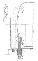
- the domestic hot water tank consists of a storage tank 2 with cold water supply 3 and hot water discharge connection arranged in a heating medium housing 1, the cold water connection 3 connected to the lower bottom 4 of the storage tank 2 fixed in its housing with its upper part or at least with its hot water discharge pipe over at least part of its length formed in the form of a corrugated tube 5 and the cold water connection 3 to its exit point from the interior 1 dem of the housing 1 has a length which is greater than the smallest distance between the wall of the storage container 2 and the surrounding housing 1.
- the formed as a corrugated tube 5 Section 5 ⁇ of the cold water connection 3 forms the greater part of its length within what ser leading housing interior 1 ⁇ , the cold water connection 3 passes through the housing wall 1 ⁇ in the region of a larger opening 6 with respect to its own diameter.
- the part of the cold water connection 3 protruding from the opening 6 extends within a hood-like cover 7 of the opening, ie the interior of this cover 7 also belongs to the interior 1 ⁇ of the housing 1.
- the passage opening edge 8 of the cover 7 is connected to the line connection end region 9 of the cold water connection 3 connected liquid-tight.
- the bottom 4 of the storage tank 2 is provided in the region of the mouth of the cold water connection 3 in the bottom 4 of the storage tank with an indentation 10 which has an orifice wall 12 perpendicular or approximately perpendicular to the longitudinal axis 11 of the cold water connection 3, which facilitates the integration of the shaft-free end of the cold water connection into the floor 4.
- the bottom 13 and shaft-free end 13 of the cold water connection 3 is supported with a support web 14 extending in the longitudinal direction of the connection against the upper boundary wall 15 of the indentation 10. This avoids any stress on the ring weld seam for the integration of the shaft-free end 13.
- the hood-like and relatively long cover 7 of the cross-sectionally round or oval through opening 6 is designed in the form of a tube piece 7 'and suitably connected in a liquid-tight manner to the peripheral edge of the through opening 6 or with a special sheet metal ring on which a connecting flange is formed, but which doesn't matter here.
- This sheet metal ring if present and as shown, must of course then have a corresponding opening aligned with the through opening 6.
- the particular design of the water-carrying housing 1 shown in this regard is also immaterial, ie the water-carrying housing 1 can be placed under the Bottom 4 of the storage container also form a closed housing, which then is not, as shown, in open connection to a housing of a firing part located under the housing 1.
- the pipe section 7 ⁇ has a length which advantageously corresponds to at least one third of the length of the cold water connection 3 extending in the water-carrying interior 1 ⁇ of the housing 1 and pipe section 7 ⁇ .
- the section 5 Well of the corrugated pipe can also be kept correspondingly long, which means that one is not forced to provide this more or less elastic part of the cold water connection with very tight and tightly folded corrugations. Therefore, the shafts 17 of the corrugated tube 5, as shown in FIG. 2, are advantageously and preferably created with a depth T that is smaller than the wavelength L.
- the accommodation of a relatively long, with a correspondingly long elastic corrugated tube section can also be achieved in that the junction 16 of the container-side end 13 of the cold water connection 3 is arranged opposite or relatively far from the penetration point on the container wall , ie, in this case, the larger part of the cold water connection 3 extends below the bottom 4 of the storage tank.
- the line connection end 9 can then be connected again in a liquid-tight manner to the edge of the passage opening 6, which is then kept correspondingly smaller.
- the arrangement of a hood-like cover 7, as described above, can then be omitted.
- Support webs 14 can, moreover, both in this embodiment and in the embodiment described above also at the line connection end 9 of the cold water water connection 3 are provided, ie, either within the cover 7 or in the second case on the container wall.
Landscapes
- Engineering & Computer Science (AREA)
- Physics & Mathematics (AREA)
- Thermal Sciences (AREA)
- Chemical & Material Sciences (AREA)
- Combustion & Propulsion (AREA)
- Mechanical Engineering (AREA)
- General Engineering & Computer Science (AREA)
- Heat-Pump Type And Storage Water Heaters (AREA)
- Cookers (AREA)
- Thermally Insulated Containers For Foods (AREA)
- Details Of Fluid Heaters (AREA)
- Housings, Intake/Discharge, And Installation Of Fluid Heaters (AREA)
Priority Applications (1)
| Application Number | Priority Date | Filing Date | Title |
|---|---|---|---|
| AT88103844T ATE68585T1 (de) | 1987-03-16 | 1988-03-11 | Brauchwasserspeicher. |
Applications Claiming Priority (4)
| Application Number | Priority Date | Filing Date | Title |
|---|---|---|---|
| DE8703893U | 1987-03-16 | ||
| DE8703893U DE8703893U1 (de) | 1987-03-16 | 1987-03-16 | Gasheizkessel |
| DE8801491U | 1988-02-06 | ||
| DE8801491U DE8801491U1 (de) | 1988-02-06 | 1988-02-06 | Brauchwasserspeicher |
Publications (3)
| Publication Number | Publication Date |
|---|---|
| EP0282916A2 true EP0282916A2 (fr) | 1988-09-21 |
| EP0282916A3 EP0282916A3 (en) | 1990-05-23 |
| EP0282916B1 EP0282916B1 (fr) | 1991-10-16 |
Family
ID=25951614
Family Applications (1)
| Application Number | Title | Priority Date | Filing Date |
|---|---|---|---|
| EP88103844A Expired - Lifetime EP0282916B1 (fr) | 1987-03-16 | 1988-03-11 | Appareil de chauffage à accumulation d'eau |
Country Status (3)
| Country | Link |
|---|---|
| EP (1) | EP0282916B1 (fr) |
| AT (1) | ATE68585T1 (fr) |
| DE (1) | DE3865469D1 (fr) |
Families Citing this family (1)
| Publication number | Priority date | Publication date | Assignee | Title |
|---|---|---|---|---|
| FR3155889B1 (fr) * | 2023-11-24 | 2026-01-23 | Burnsen Sa | Installation de préparation d’eau chaude sanitaire |
Family Cites Families (3)
| Publication number | Priority date | Publication date | Assignee | Title |
|---|---|---|---|---|
| DE1944049U (de) * | 1963-06-28 | 1966-08-11 | Wilhelm Ganhoer | Stehender stahlheizkessel mit warmwasserboiler fuer oelfeuerung, gas und feste brennstoffe. |
| DE7031491U (de) * | 1970-08-22 | 1970-11-19 | Junkers & Co | Vorrichtung zum anschliessen eines gasbeheizten durchlauf-wassererhitzers. |
| DE8703893U1 (de) * | 1987-03-16 | 1987-04-30 | Viessmann Werke GmbH & Co, 3559 Allendorf | Gasheizkessel |
-
1988
- 1988-03-11 AT AT88103844T patent/ATE68585T1/de active
- 1988-03-11 DE DE8888103844T patent/DE3865469D1/de not_active Expired - Lifetime
- 1988-03-11 EP EP88103844A patent/EP0282916B1/fr not_active Expired - Lifetime
Also Published As
| Publication number | Publication date |
|---|---|
| ATE68585T1 (de) | 1991-11-15 |
| EP0282916A3 (en) | 1990-05-23 |
| EP0282916B1 (fr) | 1991-10-16 |
| DE3865469D1 (de) | 1991-11-21 |
Similar Documents
| Publication | Publication Date | Title |
|---|---|---|
| DE60006296T2 (de) | Dampferzeuger für Reinigungsmaschinen, Bügeleisen, Kaffemaschinen und ähnliche Maschinen | |
| DE102007026968B4 (de) | Wärmetauscher, Warmwasserbereiter und Wasserrohr | |
| DE112007003721T5 (de) | Verbundbehälter für Pulver-oder Partikelmaterial | |
| DE2646234A1 (de) | Heizkoerper | |
| EP0282916B1 (fr) | Appareil de chauffage à accumulation d'eau | |
| DE102009002712B4 (de) | Heißwasserbereiter und Wasserverteilvorrichtung für Heißwasserbereiter | |
| DE8801491U1 (de) | Brauchwasserspeicher | |
| DE9007155U1 (de) | Kaltwasser-Einlaufrohr | |
| EP0536654B1 (fr) | Accumulateur à enveloppe double | |
| EP2294340B1 (fr) | Chauffe-eau | |
| DE2911020B1 (de) | Stahlheizungskessel | |
| DE2657991C2 (de) | Heißwasserbereiter, insbesondere Speicher | |
| EP0338120A2 (fr) | Unité de chaudière de chauffage - appareil de chauffage à accumulation | |
| DE3736321C1 (en) | Boiler | |
| EP0121749B1 (fr) | Appareil pour le chauffage et la technique thermique | |
| DE2839966C2 (de) | Verbindungsausbildung für flächige Gehäuseteile | |
| DE2303971C3 (de) | Festdach für Großbehälter, insbesondere Lagertanks | |
| DE8317442U1 (de) | Gehaeuse mit mindestens einem darin angeordneten brauchwasserspeicherbehaelter | |
| DE8318372U1 (de) | Speicher, insbesondere pufferspeicher | |
| CH657206A5 (en) | Heater | |
| DE1679782B1 (de) | Heizkessel mit Boiler zur Erzeugung und Speicherung von warmem bzw.heissem Brauchwasser | |
| DE10225508C1 (de) | Gußgliederkessel | |
| DE3202649A1 (de) | Waermespeicher, insbesondere fuer warmwasserheizungsanlagen | |
| DE29518237U1 (de) | Heizgaszugtasche | |
| DE1526922A1 (de) | Dampferzeuger mit Rauchgaszug |
Legal Events
| Date | Code | Title | Description |
|---|---|---|---|
| PUAI | Public reference made under article 153(3) epc to a published international application that has entered the european phase |
Free format text: ORIGINAL CODE: 0009012 |
|
| AK | Designated contracting states |
Kind code of ref document: A2 Designated state(s): AT BE CH DE FR IT LI NL SE |
|
| PUAL | Search report despatched |
Free format text: ORIGINAL CODE: 0009013 |
|
| AK | Designated contracting states |
Kind code of ref document: A3 Designated state(s): AT BE CH DE FR IT LI NL SE |
|
| RHK1 | Main classification (correction) |
Ipc: F24H 1/22 |
|
| 17P | Request for examination filed |
Effective date: 19900518 |
|
| 17Q | First examination report despatched |
Effective date: 19910225 |
|
| GRAA | (expected) grant |
Free format text: ORIGINAL CODE: 0009210 |
|
| AK | Designated contracting states |
Kind code of ref document: B1 Designated state(s): AT BE CH DE FR IT LI NL SE |
|
| REF | Corresponds to: |
Ref document number: 68585 Country of ref document: AT Date of ref document: 19911115 Kind code of ref document: T |
|
| ET | Fr: translation filed | ||
| REF | Corresponds to: |
Ref document number: 3865469 Country of ref document: DE Date of ref document: 19911121 |
|
| ITF | It: translation for a ep patent filed | ||
| PLBE | No opposition filed within time limit |
Free format text: ORIGINAL CODE: 0009261 |
|
| STAA | Information on the status of an ep patent application or granted ep patent |
Free format text: STATUS: NO OPPOSITION FILED WITHIN TIME LIMIT |
|
| 26N | No opposition filed | ||
| PGFP | Annual fee paid to national office [announced via postgrant information from national office to epo] |
Ref country code: SE Payment date: 19940228 Year of fee payment: 7 |
|
| PGFP | Annual fee paid to national office [announced via postgrant information from national office to epo] |
Ref country code: BE Payment date: 19940303 Year of fee payment: 7 |
|
| PGFP | Annual fee paid to national office [announced via postgrant information from national office to epo] |
Ref country code: CH Payment date: 19940324 Year of fee payment: 7 |
|
| PGFP | Annual fee paid to national office [announced via postgrant information from national office to epo] |
Ref country code: FR Payment date: 19940330 Year of fee payment: 7 |
|
| PGFP | Annual fee paid to national office [announced via postgrant information from national office to epo] |
Ref country code: NL Payment date: 19940331 Year of fee payment: 7 Ref country code: AT Payment date: 19940331 Year of fee payment: 7 |
|
| EAL | Se: european patent in force in sweden |
Ref document number: 88103844.2 |
|
| PG25 | Lapsed in a contracting state [announced via postgrant information from national office to epo] |
Ref country code: AT Effective date: 19950311 |
|
| PG25 | Lapsed in a contracting state [announced via postgrant information from national office to epo] |
Ref country code: SE Effective date: 19950312 |
|
| PG25 | Lapsed in a contracting state [announced via postgrant information from national office to epo] |
Ref country code: LI Effective date: 19950331 Ref country code: CH Effective date: 19950331 Ref country code: BE Effective date: 19950331 |
|
| BERE | Be: lapsed |
Owner name: VIESSMANN HANS Effective date: 19950331 |
|
| PG25 | Lapsed in a contracting state [announced via postgrant information from national office to epo] |
Ref country code: NL Effective date: 19951001 |
|
| PG25 | Lapsed in a contracting state [announced via postgrant information from national office to epo] |
Ref country code: FR Free format text: LAPSE BECAUSE OF NON-PAYMENT OF DUE FEES Effective date: 19951130 |
|
| REG | Reference to a national code |
Ref country code: CH Ref legal event code: PL |
|
| NLV4 | Nl: lapsed or anulled due to non-payment of the annual fee |
Effective date: 19951001 |
|
| EUG | Se: european patent has lapsed |
Ref document number: 88103844.2 |
|
| REG | Reference to a national code |
Ref country code: FR Ref legal event code: ST |
|
| PGFP | Annual fee paid to national office [announced via postgrant information from national office to epo] |
Ref country code: DE Payment date: 19990331 Year of fee payment: 12 |
|
| PG25 | Lapsed in a contracting state [announced via postgrant information from national office to epo] |
Ref country code: DE Free format text: LAPSE BECAUSE OF NON-PAYMENT OF DUE FEES Effective date: 20010103 |
|
| PG25 | Lapsed in a contracting state [announced via postgrant information from national office to epo] |
Ref country code: IT Free format text: LAPSE BECAUSE OF NON-PAYMENT OF DUE FEES;WARNING: LAPSES OF ITALIAN PATENTS WITH EFFECTIVE DATE BEFORE 2007 MAY HAVE OCCURRED AT ANY TIME BEFORE 2007. THE CORRECT EFFECTIVE DATE MAY BE DIFFERENT FROM THE ONE RECORDED. Effective date: 20050311 |