EP0282919B1 - Joint d'étanchéité pour fenêtre - Google Patents
Joint d'étanchéité pour fenêtre Download PDFInfo
- Publication number
- EP0282919B1 EP0282919B1 EP88103859A EP88103859A EP0282919B1 EP 0282919 B1 EP0282919 B1 EP 0282919B1 EP 88103859 A EP88103859 A EP 88103859A EP 88103859 A EP88103859 A EP 88103859A EP 0282919 B1 EP0282919 B1 EP 0282919B1
- Authority
- EP
- European Patent Office
- Prior art keywords
- window glass
- window
- connecting bridge
- glass sealing
- sealing
- Prior art date
- Legal status (The legal status is an assumption and is not a legal conclusion. Google has not performed a legal analysis and makes no representation as to the accuracy of the status listed.)
- Expired - Lifetime
Links
- 238000007789 sealing Methods 0.000 title claims description 46
- 239000005357 flat glass Substances 0.000 title claims 12
- 230000003014 reinforcing effect Effects 0.000 claims description 12
- 239000002184 metal Substances 0.000 claims description 10
- 239000011248 coating agent Substances 0.000 claims description 3
- 238000000576 coating method Methods 0.000 claims description 3
- 238000005452 bending Methods 0.000 claims 1
- 230000002787 reinforcement Effects 0.000 description 11
- 238000004073 vulcanization Methods 0.000 description 9
- 238000004873 anchoring Methods 0.000 description 4
- 238000004519 manufacturing process Methods 0.000 description 3
- 238000000926 separation method Methods 0.000 description 2
- 239000000853 adhesive Substances 0.000 description 1
- 230000001070 adhesive effect Effects 0.000 description 1
- 230000015572 biosynthetic process Effects 0.000 description 1
- 238000010924 continuous production Methods 0.000 description 1
- KAATUXNTWXVJKI-UHFFFAOYSA-N cypermethrin Chemical compound CC1(C)C(C=C(Cl)Cl)C1C(=O)OC(C#N)C1=CC=CC(OC=2C=CC=CC=2)=C1 KAATUXNTWXVJKI-UHFFFAOYSA-N 0.000 description 1
- 238000004049 embossing Methods 0.000 description 1
- 238000001125 extrusion Methods 0.000 description 1
- 210000001503 joint Anatomy 0.000 description 1
- 239000004922 lacquer Substances 0.000 description 1
- 230000001050 lubricating effect Effects 0.000 description 1
- 239000000463 material Substances 0.000 description 1
- 238000000034 method Methods 0.000 description 1
- 230000007704 transition Effects 0.000 description 1
- 239000002699 waste material Substances 0.000 description 1
Images

Classifications
-
- B—PERFORMING OPERATIONS; TRANSPORTING
- B60—VEHICLES IN GENERAL
- B60J—WINDOWS, WINDSCREENS, NON-FIXED ROOFS, DOORS, OR SIMILAR DEVICES FOR VEHICLES; REMOVABLE EXTERNAL PROTECTIVE COVERINGS SPECIALLY ADAPTED FOR VEHICLES
- B60J1/00—Windows; Windscreens; Accessories therefor
- B60J1/08—Windows; Windscreens; Accessories therefor arranged at vehicle sides
- B60J1/12—Windows; Windscreens; Accessories therefor arranged at vehicle sides adjustable
- B60J1/16—Windows; Windscreens; Accessories therefor arranged at vehicle sides adjustable slidable
- B60J1/17—Windows; Windscreens; Accessories therefor arranged at vehicle sides adjustable slidable vertically
-
- B—PERFORMING OPERATIONS; TRANSPORTING
- B60—VEHICLES IN GENERAL
- B60J—WINDOWS, WINDSCREENS, NON-FIXED ROOFS, DOORS, OR SIMILAR DEVICES FOR VEHICLES; REMOVABLE EXTERNAL PROTECTIVE COVERINGS SPECIALLY ADAPTED FOR VEHICLES
- B60J10/00—Sealing arrangements
- B60J10/15—Sealing arrangements characterised by the material
- B60J10/18—Sealing arrangements characterised by the material provided with reinforcements or inserts
-
- B—PERFORMING OPERATIONS; TRANSPORTING
- B60—VEHICLES IN GENERAL
- B60J—WINDOWS, WINDSCREENS, NON-FIXED ROOFS, DOORS, OR SIMILAR DEVICES FOR VEHICLES; REMOVABLE EXTERNAL PROTECTIVE COVERINGS SPECIALLY ADAPTED FOR VEHICLES
- B60J10/00—Sealing arrangements
- B60J10/20—Sealing arrangements characterised by the shape
-
- B—PERFORMING OPERATIONS; TRANSPORTING
- B60—VEHICLES IN GENERAL
- B60J—WINDOWS, WINDSCREENS, NON-FIXED ROOFS, DOORS, OR SIMILAR DEVICES FOR VEHICLES; REMOVABLE EXTERNAL PROTECTIVE COVERINGS SPECIALLY ADAPTED FOR VEHICLES
- B60J10/00—Sealing arrangements
- B60J10/20—Sealing arrangements characterised by the shape
- B60J10/23—Sealing arrangements characterised by the shape assembled from two or more parts
- B60J10/233—Modular sealing arrangements, i.e. arrangements built up from a large number of joined modules
- B60J10/2335—Modular sealing arrangements, i.e. arrangements built up from a large number of joined modules with joint end members, e.g. abutting ends
-
- B—PERFORMING OPERATIONS; TRANSPORTING
- B60—VEHICLES IN GENERAL
- B60J—WINDOWS, WINDSCREENS, NON-FIXED ROOFS, DOORS, OR SIMILAR DEVICES FOR VEHICLES; REMOVABLE EXTERNAL PROTECTIVE COVERINGS SPECIALLY ADAPTED FOR VEHICLES
- B60J10/00—Sealing arrangements
- B60J10/30—Sealing arrangements characterised by the fastening means
-
- B—PERFORMING OPERATIONS; TRANSPORTING
- B60—VEHICLES IN GENERAL
- B60J—WINDOWS, WINDSCREENS, NON-FIXED ROOFS, DOORS, OR SIMILAR DEVICES FOR VEHICLES; REMOVABLE EXTERNAL PROTECTIVE COVERINGS SPECIALLY ADAPTED FOR VEHICLES
- B60J10/00—Sealing arrangements
- B60J10/70—Sealing arrangements specially adapted for windows or windscreens
- B60J10/74—Sealing arrangements specially adapted for windows or windscreens for sliding window panes, e.g. sash guides
-
- B—PERFORMING OPERATIONS; TRANSPORTING
- B60—VEHICLES IN GENERAL
- B60J—WINDOWS, WINDSCREENS, NON-FIXED ROOFS, DOORS, OR SIMILAR DEVICES FOR VEHICLES; REMOVABLE EXTERNAL PROTECTIVE COVERINGS SPECIALLY ADAPTED FOR VEHICLES
- B60J10/00—Sealing arrangements
- B60J10/70—Sealing arrangements specially adapted for windows or windscreens
- B60J10/74—Sealing arrangements specially adapted for windows or windscreens for sliding window panes, e.g. sash guides
- B60J10/75—Sealing arrangements specially adapted for windows or windscreens for sliding window panes, e.g. sash guides for sealing the lower part of the panes
Definitions
- the invention relates to a window frame made of rubber or the like.
- movable (retractable) windows in vehicles which surrounds a window cutout and two body flanges, which are approximately U-shaped in cross-section and, in the assembled state, the window has sealing strips between them , which are integrally connected to each other in the area of the upper edge and the two side edges of the window cutout by a connecting bridge running approximately perpendicular to the pane plane, the connecting bridge being separated from the sealing strips in the area of the lower edge of the window cutout.
- a pane surround of the generic type has become known from DE-A 3 226 106.
- the sealing strips are unreinforced, i.e. formed without a reinforcing insert embedded therein, which disadvantageously results in a difficult anchoring at the window cutout and the need to provide anchoring elements such as spring clips or the like.
- the present invention has for its object to provide a window bezel of the type mentioned in the introduction, which is reinforced in the area of the sealing strips, simple and easy, in particular without additional anchoring elements, can compensate for manufacturing tolerances and the technical requirements as well as the aesthetic able to fulfill.
- each sealing strip of the window frame consisting of an extrusion profile is continuously equipped with an embedded reinforcement insert, that each reinforcement insert is tensile and compressive, but flexible or flexible, externally smooth and approximately U-shaped in cross section, that the sealing strips and the connecting bridge form a closed frame by means of a butt joint vulcanization point provided on them and that the butt vulcanizing point is kept free of the reinforcing insert, and that the connecting bridge is separated from the sealing strips in the region of the lower edge of the window cutout.
- the pane surround according to the invention offers a number of essential advantages.
- the reinforcement insert embedded in the sealing strips results in simple assembly and reliable holding of the pane surround on the body flanges.
- the measure of making the reinforcement inserts smooth advantageously has the result that the surface of the pane surround also has a smooth design without sink marks, markings or the like and thus meets the aesthetic requirements.
- the formation of a self-contained frame eliminates sealing problems, the impact vulcanization point provided thereby still compensating for tolerances, because no reinforcement insert is deliberately arranged in the vulcanization point area.
- the part of the connecting bridge separated from the sealing strips e.g. is cut through in the middle and that the end regions of the connecting bridge thus formed form additional pane entries running in a downward extension of the two side edges of the window cutout.
- the part separated from the sealing strips is therefore not waste but an advantageous functional part of the pane surround according to the invention.
- a further embodiment of the invention is advantageous, according to which it is provided that the sealing strips and the connecting bridge with sealing lips coming into contact with the pane are trained.
- the connecting bridge has an approximately U-shaped cross section and is connected to the leg ends via a relatively thin, continuous connecting web with the sealing strips. After the connecting webs have been cut in, they can practically be used as a ripcord for severing the corresponding connecting bridge part. Unintentional tearing can be prevented by pre-machined punch holes or the like.
- a relatively (for example up to 30 mm) long reinforcement-free vulcanization point is provided between the ends of the sealing strips and the connecting bridge, because the pane surround is compressible in the area of the vulcanization point is stretchable.
- the vulcanization point is arranged in a preferably lower corner area of the window frame, which results in a largely concealed placement, in particular if there is a mirror triangle of a vehicle exterior mirror in this corner area.
- each reinforcement insert is formed from a U-shaped profiled metal strip, which consists of at least one continuous web and a plurality of rungs arranged next to one another transversely to the longitudinal axis of the strip without spacing. The spacing-free arrangement of the rungs prevents sink marks in the pane surround.
- each reinforcing insert has a web in the base leg of the U-shaped metal strip and on both sides of the web spaced apart next to each other rungs.
- Each reinforcement insert consists of a pre-cut, smooth-rolled and U-shaped profiled metal strip, which has a double-sided adhesive coating for the purpose of perfect anchoring in the rubber material.
- a door frame 1 of a vehicle is shown, more schematically, which has a window frame surrounding a window cutout 2.
- the window section 2 is delimited by an upper edge 3, a lower edge 4 and two side edges 5.
- the pane surround is designed as a self-contained frame and has an impact vulcanization point 6.
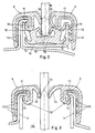
- the window frame is designed as a window guide profile shown in more detail in FIG. 2, while the false window frame in the area of the lower edge 4 of the window section consists of a window shaft seal shown in more detail in FIG. 3.
- the cross-sectional view according to FIG. 2 reveals that the window bezel formed here as a window guide profile has two pluggable on body flanges 7, approximately U-shaped in cross-section, in the assembled state the window pane 8 indicated by dash-dotted lines has sealing strips 9 between them, which are separated by an approximately vertical line connecting bridge 10 extending to the pane plane and supported on the pane edge are integrally connected to one another.
- the sealing strips 9 are each equipped with an embedded reinforcement insert 11, to be described with reference to FIGS. 4 to 6, which, like the sealing strips 9, have an approximately U-shaped cross section.
- the connecting bridge 10 is also U-shaped in cross section and is connected to the leg ends via a relatively thin, continuous connecting web 12 with the sealing strips 9.
- Each sealing strip 9 forms a clamp mouth which can be plugged in over a body flange 7 and has retaining lips 13 which are supported on the body flange 7. These retaining lips 13, as a comparison of the left to the right side of the drawing shows, can be designed differently.
- the connecting bridge 10 is also provided on the outside with molded-on retaining lips 14 in order to improve the reliability of the window mount holder.
- sealing strips 9 and the connecting bridge 10 have, on their sides adjacent to the window pane 8, sealing lips 15 which are made particularly slidable on the pane contact surfaces, specifically by means of flocking 15, a lubricating lacquer coating or the like.
- a corresponding flocking 15 or the like. is also provided on the edge of the pane of the connecting bridge 10 coming to rest.
- pane surround in the area of the upper edge 3 and the side edges 5 of the window cutout 2 has the cross-sectional shape shown in FIG. 2, there is another cross-sectional shape in the area of the lower edge 4 of the window cutout 2, namely the cross-sectional shape shown in FIG. 3, which differs from that 2, however, only differs in that the connecting bridge 10 along the connecting webs 12 has been separated from the sealing strips 9 in order to enable disk movement.
- the butt vulcanization point 6 is relatively long and, in particular, has no reinforcement insert, so that tolerance compensation can be carried out in the region of the vulcanization point.
- the reinforcing insert 11 shown in FIGS. 4 to 6 is a metal tape which has been pre-cut and has the special feature that it has a continuously smooth surface.
- the metal strip has a web 19 running through in the longitudinal direction, on which rungs 20 cut free on both sides and oriented perpendicular to the web 19 sit practically without clearance.
- the spacing-free arrangement of the rungs next to each other results from the fact that they are separated from one another only by an embossed cut and not by a punch opening.
- a metal strip is therefore provided with embossed cuts 21 in a continuous process, which results in a continuous web 19 with rungs 20 attached to it on both sides.
- the metal strip is then rolled in order to smooth the deformations caused by the embossing cuts and roll-formed into a U-shaped cross section.
- the web is located in the base leg of the reinforcement insert.
Landscapes
- Engineering & Computer Science (AREA)
- Mechanical Engineering (AREA)
- Seal Device For Vehicle (AREA)
- Window Of Vehicle (AREA)
Claims (10)
Applications Claiming Priority (2)
| Application Number | Priority Date | Filing Date | Title |
|---|---|---|---|
| DE3708888 | 1987-03-19 | ||
| DE19873708888 DE3708888A1 (de) | 1987-03-19 | 1987-03-19 | Scheibeneinfassung |
Publications (2)
| Publication Number | Publication Date |
|---|---|
| EP0282919A1 EP0282919A1 (fr) | 1988-09-21 |
| EP0282919B1 true EP0282919B1 (fr) | 1990-06-20 |
Family
ID=6323430
Family Applications (1)
| Application Number | Title | Priority Date | Filing Date |
|---|---|---|---|
| EP88103859A Expired - Lifetime EP0282919B1 (fr) | 1987-03-19 | 1988-03-11 | Joint d'étanchéité pour fenêtre |
Country Status (5)
| Country | Link |
|---|---|
| US (1) | US4809463A (fr) |
| EP (1) | EP0282919B1 (fr) |
| JP (1) | JPH0755625B2 (fr) |
| DE (2) | DE3708888A1 (fr) |
| ES (1) | ES2015974B3 (fr) |
Cited By (2)
| Publication number | Priority date | Publication date | Assignee | Title |
|---|---|---|---|---|
| DE10313601A1 (de) * | 2003-03-26 | 2004-10-14 | Metzeler Automotive Profile Systems Gmbh | Dichtungsanordnung zum Abdichten und Führen einer bewegbaren Fensterscheibe, insbesondere eines Kraftfahrzeugs |
| DE102007018790A1 (de) | 2007-04-20 | 2008-10-23 | Metzeler Automotive Profile Systems Gmbh | Verfahren und Vorrichtung zum Herstellen einer Verbindung zwischen Profilabschnitten und Dichtung, insbesondere zum Abdichten eines Schließelements eines Kraftfahrzeugs |
Families Citing this family (28)
| Publication number | Priority date | Publication date | Assignee | Title |
|---|---|---|---|---|
| FR2627835B1 (fr) * | 1988-02-26 | 1991-05-17 | Hutchinson | Coulisse d'etancheite de glace mobile, notamment de vitre de vehicule automobile |
| US5129193A (en) * | 1988-12-27 | 1992-07-14 | Ford Motor Company | Sealing system for movable dual pane glass |
| DE3933250A1 (de) * | 1989-10-05 | 1991-04-11 | Continental Ag | Verriegelbares abdicht- und fuellerprofil, insbesondere fuer fenster von kraftfahrzeugen |
| JP2541836Y2 (ja) * | 1991-03-31 | 1997-07-23 | 日産車体株式会社 | 昇降式ウインドウのグラスラン構造 |
| US5086588A (en) * | 1991-04-29 | 1992-02-11 | Toyoda Gosei Co. Ltd. | Glass run for motor vehicle |
| FR2689457B1 (fr) * | 1992-04-02 | 1995-08-18 | Technistan | Joint d'etancheite pour vitres coulissantes de vehicule. |
| US5396733A (en) * | 1993-06-09 | 1995-03-14 | Gencorp Inc. | Seal assembly for a movable window for a vehicle |
| FR2714334B1 (fr) * | 1993-12-28 | 1996-03-15 | Technistan | Dispositif de retenue d'un joint d'étanchéité sur un cadre de porte de véhicule automobile. |
| DE4435088A1 (de) * | 1994-09-30 | 1996-04-11 | Metzeler Automotive Profiles | Dichtungsanordnung für eine bewegliche Fensterscheibe |
| US5566510A (en) * | 1994-10-26 | 1996-10-22 | Gencorp Inc. | Molded glass run channel corner assembly |
| US6070364A (en) * | 1997-02-13 | 2000-06-06 | Schlegel Corporation | Flush glass seal insert with a belt-line extension |
| DE102004020857A1 (de) * | 2004-04-28 | 2005-11-17 | Metzeler Automotive Profile Systems Gmbh | Verstärkungsträger, Dichtung mit einem solchen Verstärkungsträger und Verfahren zum Herstellen einer solchen Dichtung |
| JP3713547B2 (ja) * | 2000-08-30 | 2005-11-09 | 豊田合成株式会社 | 自動車用ガラスラン |
| US7062880B2 (en) * | 2002-10-19 | 2006-06-20 | General Motors Corporation | Stabilizer clip for window assembly |
| JP2006044360A (ja) * | 2004-08-02 | 2006-02-16 | Toyoda Gosei Co Ltd | ガラスラン |
| ES2331445B1 (es) * | 2006-06-12 | 2010-09-14 | Metalurgicas Pabur, S.L. | Procedimiento de saneado de extremos de un perfil de estanqueidad compuesto de elastomero y alma metalica y dispositivo para realizarlo. |
| US7481028B2 (en) | 2006-07-17 | 2009-01-27 | Anderson Corporation | Mulling and sealing system for compound fenestration units |
| US20080178532A1 (en) * | 2007-01-26 | 2008-07-31 | Gm Global Technology Operations, Inc. | Sealing Arrangements for Automotive Doors |
| JP5003384B2 (ja) * | 2007-09-27 | 2012-08-15 | 豊田合成株式会社 | 自動車用ガラスラン |
| WO2011009116A1 (fr) | 2009-07-17 | 2011-01-20 | Cooper-Standard Automotive Inc. | Profilé en u co-extrudé comportant une coulisse de glace intégrée |
| US20130086865A1 (en) * | 2011-10-11 | 2013-04-11 | James Schoonover | Window seal extruded weather strip |
| ITTO20120272A1 (it) * | 2012-03-27 | 2013-09-28 | Cooper Standard Automotive Italy S P A | Guarnizione guida-vetro per il lato superiore di un'apertura di finestra di un autoveicolo |
| DE102012023043A1 (de) * | 2012-05-10 | 2013-11-14 | GM Global Technology Operations LLC (n. d. Gesetzen des Staates Delaware) | Dichtleiste für ein Kraftfahrzeug, insbesondere Fensterschachtdichtleiste |
| JP5976411B2 (ja) * | 2012-06-20 | 2016-08-23 | 西川ゴム工業株式会社 | グラスラン及びグラスランのドアガラス組付方法 |
| US10233688B1 (en) | 2015-02-16 | 2019-03-19 | Andersen Corporation | Compound fenestration assembly mull joints and methods |
| US9932765B1 (en) | 2015-02-16 | 2018-04-03 | Andersen Corporation | Compound fenestration assembly mull joints and methods |
| US10626664B1 (en) | 2015-02-16 | 2020-04-21 | Andersen Corporation | Compound fenestration assembly mull joints and methods |
| US12116829B1 (en) | 2021-09-09 | 2024-10-15 | Andersen Corporation | Fenestration assembly mull joints with improved strength and methods |
Family Cites Families (12)
| Publication number | Priority date | Publication date | Assignee | Title |
|---|---|---|---|---|
| US3401075A (en) * | 1965-07-14 | 1968-09-10 | Standard Products Co | Channel shaped strip structure |
| FR93308E (fr) * | 1966-12-09 | 1969-03-14 | Cie Financiere Et Commerciale | Ensemble de baie a auto-fixation pour le montage de glaces, notamment sur un véhicule automobile. |
| GB1598683A (en) * | 1977-04-28 | 1981-09-23 | Draftex Dev Ag | Channel-shaped sealing guiding or finishing strips |
| US4424976A (en) * | 1978-06-30 | 1984-01-10 | Toyoda Gosei Co., Ltd. | Channel-shaped trim with disconnected core pieces |
| GB2065210B (en) * | 1979-10-04 | 1983-03-09 | Draftex Dev Ag | Windscreen mounting arrangements |
| US4308305A (en) * | 1980-07-09 | 1981-12-29 | Helmut Albrecht | Core steel reinforcement for window guide channels and the like |
| GB2102050B (en) * | 1981-07-15 | 1984-11-21 | Ford Motor Co | Sliding window and sealing strip therefor. |
| GB2110281B (en) * | 1981-11-26 | 1985-04-17 | Silent Channel Prod Ltd | Seal; glass run |
| FR2521497A1 (fr) * | 1982-02-15 | 1983-08-19 | Mesnel Sa Ets | Nouvelles structures d'encadrement, de coulissement et d'etancheite, notamment pour des glaces mobiles et particulierement, pour des portes d'automobiles |
| US4442634A (en) * | 1982-03-26 | 1984-04-17 | Nifco Inc. | Retainer device for car wind-up window |
| JPS58156008U (ja) * | 1982-04-13 | 1983-10-18 | 三菱自動車工業株式会社 | ドアガラスのウエザストリツプ装置 |
| DE3616661A1 (de) * | 1986-05-16 | 1987-11-26 | Audi Ag | Dichtung |
-
1987
- 1987-03-19 DE DE19873708888 patent/DE3708888A1/de not_active Withdrawn
-
1988
- 1988-03-11 ES ES88103859T patent/ES2015974B3/es not_active Expired - Lifetime
- 1988-03-11 DE DE8888103859T patent/DE3860239D1/de not_active Expired - Lifetime
- 1988-03-11 US US07/166,704 patent/US4809463A/en not_active Expired - Lifetime
- 1988-03-11 EP EP88103859A patent/EP0282919B1/fr not_active Expired - Lifetime
- 1988-03-18 JP JP63063774A patent/JPH0755625B2/ja not_active Expired - Fee Related
Cited By (3)
| Publication number | Priority date | Publication date | Assignee | Title |
|---|---|---|---|---|
| DE10313601A1 (de) * | 2003-03-26 | 2004-10-14 | Metzeler Automotive Profile Systems Gmbh | Dichtungsanordnung zum Abdichten und Führen einer bewegbaren Fensterscheibe, insbesondere eines Kraftfahrzeugs |
| DE10313601B4 (de) * | 2003-03-26 | 2008-02-14 | Metzeler Automotive Profile Systems Gmbh | Dichtungsanordnung zum Abdichten und Führen einer bewegbaren Fensterscheibe, insbesondere eines Kraftfahrzeugs |
| DE102007018790A1 (de) | 2007-04-20 | 2008-10-23 | Metzeler Automotive Profile Systems Gmbh | Verfahren und Vorrichtung zum Herstellen einer Verbindung zwischen Profilabschnitten und Dichtung, insbesondere zum Abdichten eines Schließelements eines Kraftfahrzeugs |
Also Published As
| Publication number | Publication date |
|---|---|
| ES2015974B3 (es) | 1990-09-16 |
| US4809463A (en) | 1989-03-07 |
| DE3708888A1 (de) | 1988-09-29 |
| EP0282919A1 (fr) | 1988-09-21 |
| JPS63255119A (ja) | 1988-10-21 |
| DE3860239D1 (de) | 1990-07-26 |
| JPH0755625B2 (ja) | 1995-06-14 |
Similar Documents
| Publication | Publication Date | Title |
|---|---|---|
| EP0282919A1 (fr) | Joint d'étanchéité pour fenêtre | |
| DE69032289T2 (de) | Einstückiger Dichtungsstreifen | |
| DE3929159C2 (de) | Dichtprofilleiste | |
| EP0083696B1 (fr) | Carreau de verre ajustable verticalement notamment pour véhicules automobiles | |
| DE69505047T2 (de) | Verformbare Dichtung für beweglichen Fensterscheiben | |
| DE20006771U1 (de) | Dichtungsanordnung für eine bewegliche und eine angrenzende feststehende Fensterscheibe eines Fahrzeuges | |
| DE3901093C2 (de) | Kraftfahrzeugtür | |
| WO2008055982A1 (fr) | Système de guidage pour vitre mobile, en particulier d'un véhicule automobile | |
| DE69731729T2 (de) | Flexible gleitschiene für glassscheiben mit angeformtem versteifungsteil | |
| DE202010013082U1 (de) | Scheibeneinheit und deren Herstellung | |
| DE3305088A1 (de) | Dichtungs-. gleit- und zierrahmen fuer bewegliche fenster | |
| EP0282918B1 (fr) | Profilé en caoutchouc et procédé de fabrication | |
| DE4435088A1 (de) | Dichtungsanordnung für eine bewegliche Fensterscheibe | |
| DE102017004131A1 (de) | Geteiltes Fenster und Mittelsteg dafür | |
| DE2934722C2 (de) | Stoßstange für Fahrzeuge | |
| DE3230100C2 (de) | Einsatzrahmen zum Umrüsten eines einfach verglasten Flügelrahmens eines Fensters auf Isolierverglasung | |
| DE2623317A1 (de) | Traeger fuer profilstreifen mit u-foermigem querschnitt | |
| DE2432933A1 (de) | Einfassungsstreifen | |
| DE102019208772A1 (de) | Befestigungsanordnung für eine Fensterschachtleiste | |
| EP2222491B1 (fr) | Procede de fabrication d'un profil d'etancheite pour un vehicule automobile, ainsi que profil d'etancheite | |
| DE69401670T2 (de) | Dichtungsband | |
| DE10259842A1 (de) | Dichtung, insbesondere zum Abdichten von Fensterscheiben eines Kraftfahrzeugs | |
| DE2700648A1 (de) | Aus einem spiegel, einer glasscheibe oder einem aehnlichen material bestehende schiebetuer | |
| DE4339685C2 (de) | Fensterlaufschienenanordnung mit elastischem Dichtprofil | |
| EP0422592B1 (fr) | Profil maintenu par pinçage |
Legal Events
| Date | Code | Title | Description |
|---|---|---|---|
| PUAI | Public reference made under article 153(3) epc to a published international application that has entered the european phase |
Free format text: ORIGINAL CODE: 0009012 |
|
| 17P | Request for examination filed |
Effective date: 19880722 |
|
| AK | Designated contracting states |
Kind code of ref document: A1 Designated state(s): DE ES FR GB IT SE |
|
| 17Q | First examination report despatched |
Effective date: 19890712 |
|
| GRAA | (expected) grant |
Free format text: ORIGINAL CODE: 0009210 |
|
| AK | Designated contracting states |
Kind code of ref document: B1 Designated state(s): DE ES FR GB IT SE |
|
| REF | Corresponds to: |
Ref document number: 3860239 Country of ref document: DE Date of ref document: 19900726 |
|
| GBT | Gb: translation of ep patent filed (gb section 77(6)(a)/1977) | ||
| ITF | It: translation for a ep patent filed | ||
| ET | Fr: translation filed | ||
| PLBE | No opposition filed within time limit |
Free format text: ORIGINAL CODE: 0009261 |
|
| STAA | Information on the status of an ep patent application or granted ep patent |
Free format text: STATUS: NO OPPOSITION FILED WITHIN TIME LIMIT |
|
| 26N | No opposition filed | ||
| ITTA | It: last paid annual fee | ||
| REG | Reference to a national code |
Ref country code: GB Ref legal event code: 732E |
|
| REG | Reference to a national code |
Ref country code: FR Ref legal event code: TP |
|
| REG | Reference to a national code |
Ref country code: ES Ref legal event code: PC2A Owner name: DRAFTEX INDUSTRIES LIMITED |
|
| ITPR | It: changes in ownership of a european patent |
Owner name: CESSIONE;DRAFTEX INDUSTRIES LIMITED |
|
| EAL | Se: european patent in force in sweden |
Ref document number: 88103859.0 |
|
| REG | Reference to a national code |
Ref country code: FR Ref legal event code: CA |
|
| REG | Reference to a national code |
Ref country code: GB Ref legal event code: 732E |
|
| REG | Reference to a national code |
Ref country code: FR Ref legal event code: TP |
|
| REG | Reference to a national code |
Ref country code: GB Ref legal event code: IF02 |
|
| REG | Reference to a national code |
Ref country code: GB Ref legal event code: 732E |
|
| PGFP | Annual fee paid to national office [announced via postgrant information from national office to epo] |
Ref country code: IT Payment date: 20060331 Year of fee payment: 19 |
|
| PGFP | Annual fee paid to national office [announced via postgrant information from national office to epo] |
Ref country code: GB Payment date: 20070307 Year of fee payment: 20 |
|
| PGFP | Annual fee paid to national office [announced via postgrant information from national office to epo] |
Ref country code: DE Payment date: 20070308 Year of fee payment: 20 |
|
| PG25 | Lapsed in a contracting state [announced via postgrant information from national office to epo] |
Ref country code: SE Free format text: LAPSE BECAUSE OF NON-PAYMENT OF DUE FEES Effective date: 20070312 |
|
| PGFP | Annual fee paid to national office [announced via postgrant information from national office to epo] |
Ref country code: ES Payment date: 20070417 Year of fee payment: 20 |
|
| EUG | Se: european patent has lapsed | ||
| PGFP | Annual fee paid to national office [announced via postgrant information from national office to epo] |
Ref country code: SE Payment date: 20060306 Year of fee payment: 19 |
|
| REG | Reference to a national code |
Ref country code: GB Ref legal event code: PE20 Expiry date: 20080310 |
|
| PGFP | Annual fee paid to national office [announced via postgrant information from national office to epo] |
Ref country code: FR Payment date: 20070308 Year of fee payment: 20 |
|
| PG25 | Lapsed in a contracting state [announced via postgrant information from national office to epo] |
Ref country code: GB Free format text: LAPSE BECAUSE OF EXPIRATION OF PROTECTION Effective date: 20080310 |
|
| REG | Reference to a national code |
Ref country code: ES Ref legal event code: FD2A Effective date: 20080312 |
|
| PG25 | Lapsed in a contracting state [announced via postgrant information from national office to epo] |
Ref country code: ES Free format text: LAPSE BECAUSE OF EXPIRATION OF PROTECTION Effective date: 20080312 |
|
| PG25 | Lapsed in a contracting state [announced via postgrant information from national office to epo] |
Ref country code: IT Free format text: LAPSE BECAUSE OF NON-PAYMENT OF DUE FEES Effective date: 20070311 |